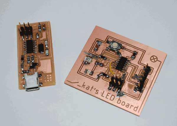
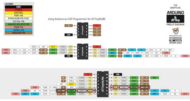
The aim of this week's assignment was to program the Hello-world circuit board to do sth. Also, read a microcontroller data sheet.
In order to get there we were supposed to use the FabISP as a programmer and then upload a program we would write that would be using the switch and the LED on the board.
First, I wrote the program on Arduino. After doing several tests with Arduino, using the breadboard to connect different circuits and trying several simple codes, I ended up with the following:
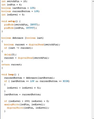
This is a program which uses the button as an input and the Led as an output. The program increases the luminosity of the Led in 3 steps and then turns it off, using the switch. The two logical variables [lastButton, currentButton] are used in order to check the current and previous state of the pins and debug the switch through debouncing the button with a 5ms delay.
Programming different circuits to operate with the arduino was really interesting and not so hard. Unexpected difficulties arose when I got to the "programming my board" part of the whole process.
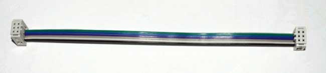
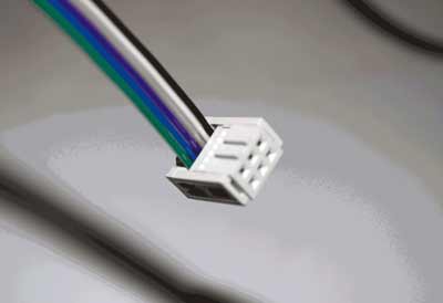
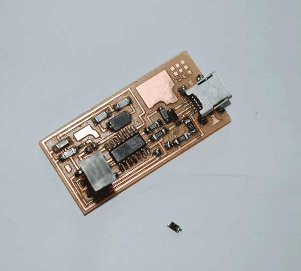
First, I made a 6-pin headers' connector in order to connect my fabISP and my Hello-board. For that I used:
- ribbon cable, and
- 2x3 female connectors
The next thing to do was to unsolder the jumpers on the FabISP in order to turn it into a programmer.
While trying to connect the 2 boards to my laptop, using the a usb cable for the FabISP, my 6-pin connector and an ftdi in the Hello-board, my computer was not recognizing my programmer.
I disconnected the circuit and tried to check again my connections with the multimeter in order to find out if something went wrong with my board.
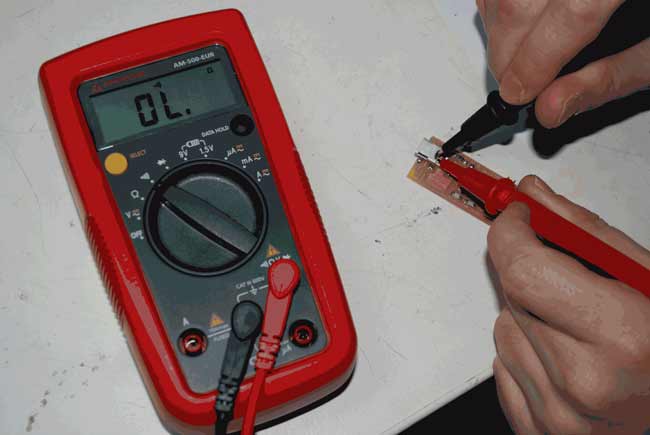
Troubleshooting the process was quite hard this time. The FabISP was programmed during the Electronics Production week and the fact that it didn't work anymore was quite disturbing. In order to check if there was something wrong with my laptop, if there were any drivers missing, I used another FabISP. This time the computer recognized the chip and the device was working properly:
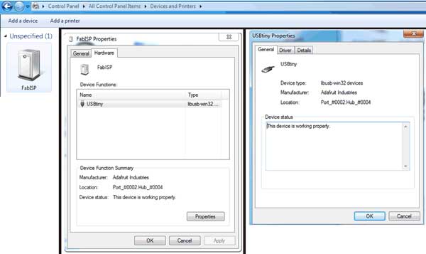
Obviously there was a problem with my board. I decided to proceed with programming my Hello-world button-Led board and come back to that afterwards.
I downloaded the latest version from www.arduino.cc before running the program. This is done simply by downloading the .zip file, extracting the content and running the .exe file.
The next thing to do was to download and install the ATtiny microcontroller support for the Arduino libraries from a GitHub repository.
I followed the instructions provided in this Sparkfun tutorial in order to install the ATtiny libraries, by creating a Hardware folder on my Arduino installation folder and placing the library's ATtiny folder inside.
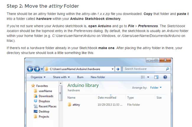
After restarting the program, I was not able to configure ATtiny on Arduino for I couldn't locate the ATtiny Microcontrollers in the Tools>Board menu. In order to make it work I had to go back to Hardware>ATtiny folder and create an AVR folder, then, simply drag and drop all equal level components inside.
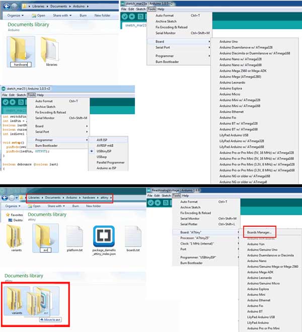
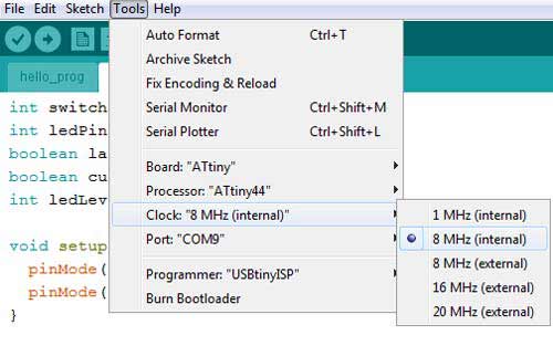
Through the Tools menu the board, the programmer and the clock can be identified. In order to program the Hello-board with the ATtiny I had to make the following selections:
- Tools > Board > ATtiny
- Tools > Processors > ATtiny44
- Tools > Programmer > USBtinyISP
- Tools > Clock > 20MHz (external) (according to the 20MHz Resonator component used on the board)
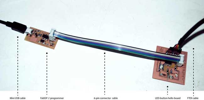
Connecting the boards to the computer.
The way to connect the bords together in order to program the ATtiny microcontroller through the FabISP is the following:
- Connect the FabISP to the computer's USB port throught a USB-miniUSB cable.
- Use the ribbon cable 6-pin header connector to connect the 2 boards.
NOTE: Make sure the ground pins of the headers are connected together. - Connect the Hello-board to the computer's USB port using an FTDI cable.
NOTE: Make sure the ground of the FTDI cable responds to the ground of the FTDI smd on the board.
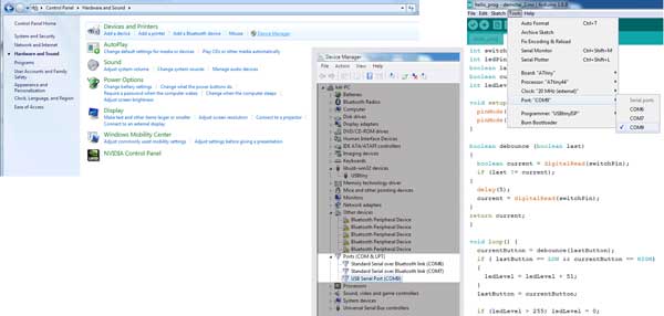
Uploading my program written on Arduino required identifying the USB port on which the FabISP was connected. To find the right one I checked on Control Panel>Device Manager>Ports. The two ports (COM6, COM7) were connected over Bluetooth, so it was COM9. I selected COM9 on Tools>Port menu on Arduino interface.
The next thing to do was to Burn the Bootloader. An error occured, multiple times, signifying there would be more difficulties to cope with.
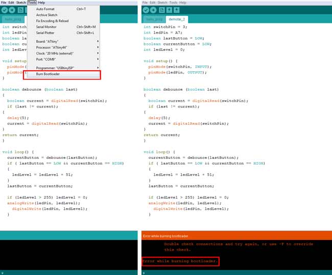
In order to identify and solve the problem I went through the following steps:
- Check all the components again with the multimeter. >>Try to Burn Bootloader.
- Check the circuit board again with the schematic from Eagle. >>If it responds to it, try to Burn Bootloader.
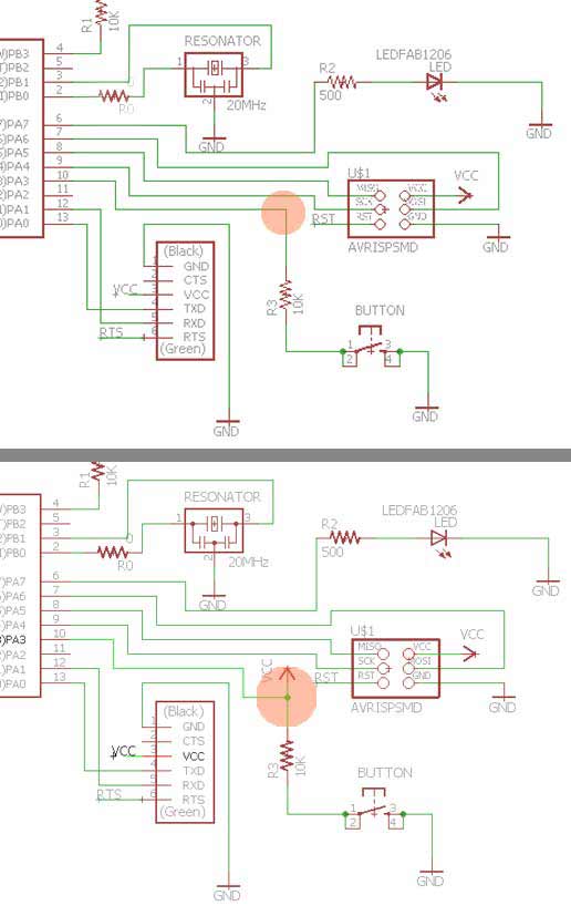
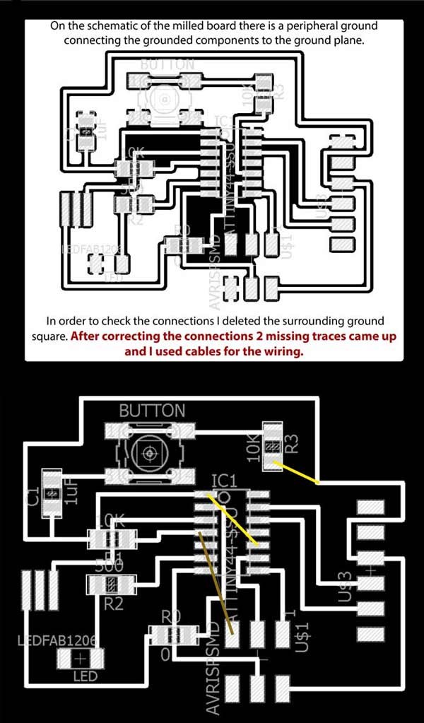
- Check the schematic on Eagle with the original schematic. >> Correct mistakes with cables. >> Try to Burn Bootloader.
Throught the troubleshooting process occured the following:
- My 20MHz resonator was not the same component as the one in other boards. In order to check if this was affecting the programming part, I tried to program it using the internal 8MHz resonator from the Arduino clock settings.
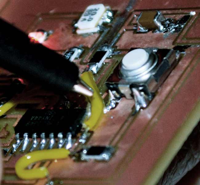
Still the Bootloader wouldn't burn. - There was a connection missing from my circuit because of a mistake on the button connection on the schematic.
- The last thing to do was to change the FTDI header on my pcb. When I was soldering the components on the board I had to use two 3-pin parts because there were no usb headers available. While heating the board, one of the parts fell off so I decided to replace the part with a normal FTDI header component.
After completing these steps I attempted to program the board again.
This time, the Bootloader burnt normally.
The next thing was to load a simple LED blink code.
Before pushing the program I used the following table to match the Arduino pins with microcontroller pins:
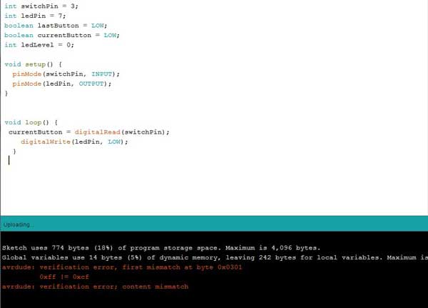
An different error came up and I considered this to be a good sign.
I checked the voltage on the 6-pin while loading. It was 5V which was perfect.
There was a slight tilt on the 6-pin header so while programming I tried pressing the ribbon cable connector down with my finger to assure it made contact.
Using the 8MHz internal clock I loaded the code again.
Unexpectedly enough, it worked!
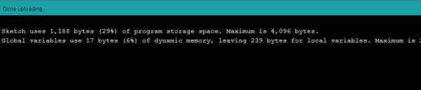
Finally, I pushed my initial code to the board to check if it was working.
                            int switchPin = 3;
                            int ledPin = 7;
                            boolean lastButton = LOW;
                            boolean currentButton = LOW;
                            int ledLevel = 0;

                            void setup() {
                              pinMode(switchPin, INPUT);
                              pinMode(ledPin, OUTPUT);
                            }

                            boolean debounce (boolean last)
                            {
                              boolean current = digitalRead(switchPin);
                              if (last != current);
                            {
                              delay(5);
                              current = digitalRead(switchPin);
                            }
                            return current;
                            }

                            void loop() {
                              currentButton = debounce(lastButton);
                              if ( lastButton == LOW && currentButton == HIGH)
                              {
                                ledLevel = ledLevel + 51;
                              }
                              lastButton = currentButton;

                              if (ledLevel > 255) ledLevel = 0;
                              analogWrite(ledPin, ledLevel);
                                digitalWrite(ledPin, ledLevel);
                              }
It was supposed to use make the LED gain full brightness in 5 steps, using at the same time a debounce switch function.
The LED responded in the on//off press button steps but the gradual gain in brightness didn't show.
I think that this is due to the fact that I declared a digital pin [7] for my LED, instead of an analog pin [A7]. I will try to reprogram my board and fix this asap.
Here you can find the file for this assignment.