For this weeks assignment, I started by trying to understand the steps of the process of milling with the CNC machine before proceeding with a design to be realized. At the same time, I used Grasshopper in order to parametrize and test the pressfit joints of my wooden structure.
The concept of designing a 3d object using a single piece of 1250x2550mm chipboard, using a flat end mill-bit set actual restrictions to the design possibilites.
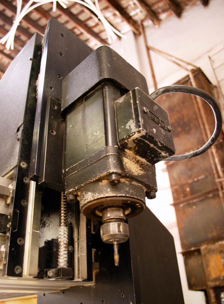
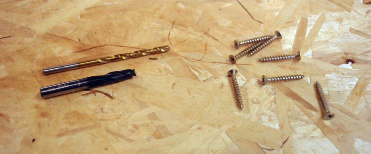
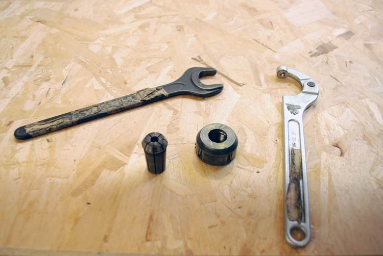
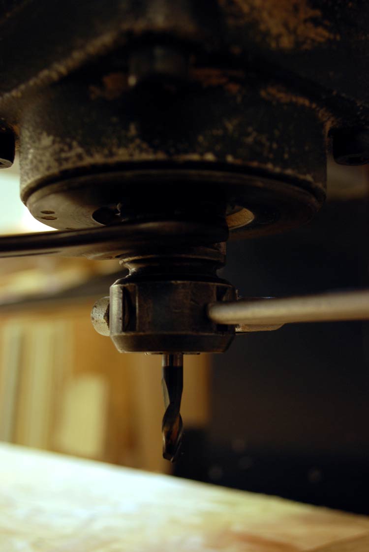
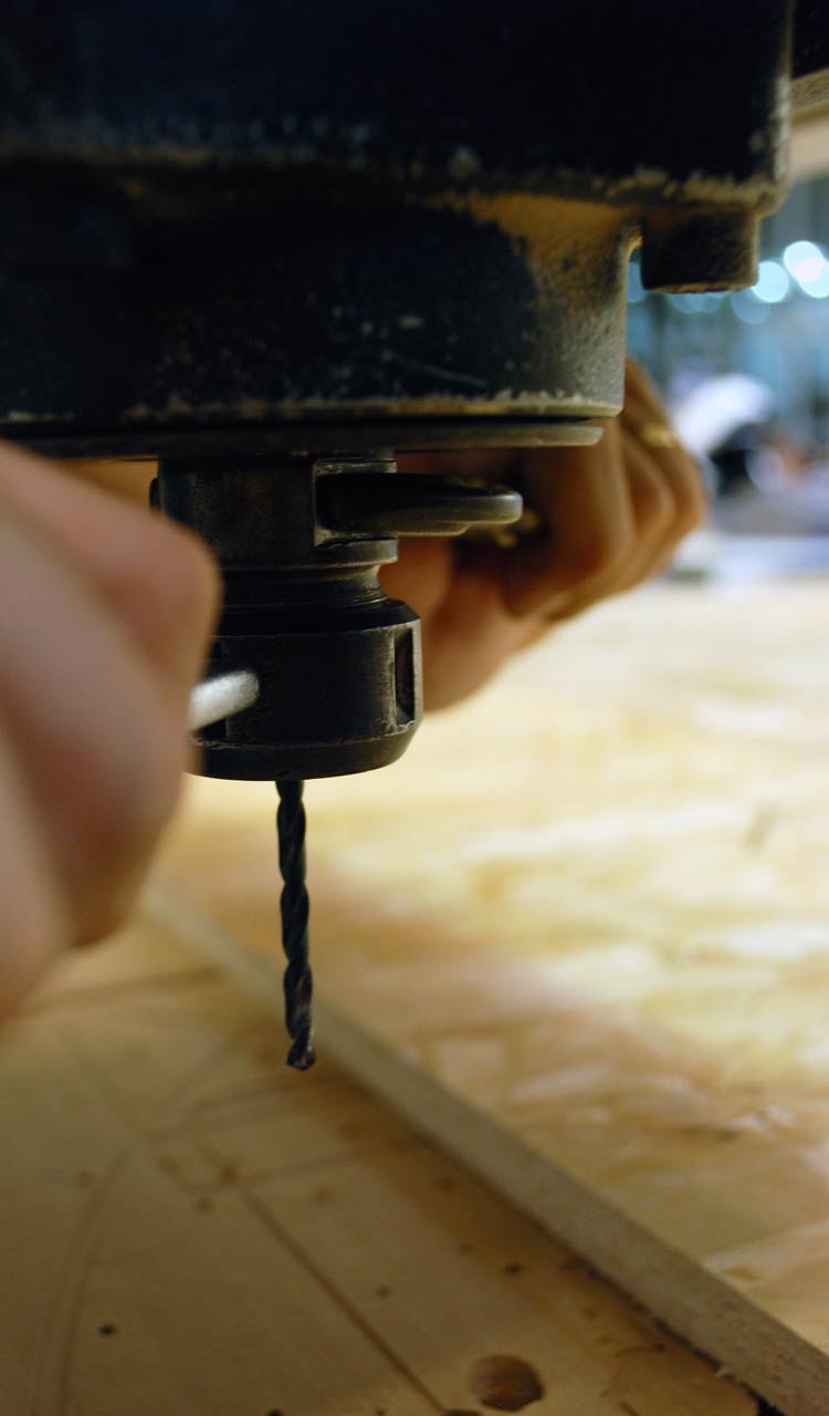
Getting familiar with the milling machine. Here's the head, the milling bits, and the tools needed in order to change them.
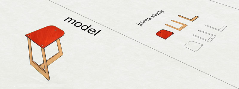
For this assignment, I came up with multiple design ideas among which I am presenting two. At first, trying to grasp the creative process inside the CAD program, I made a quick trial model. Working on this I seized the opportunity to build some skills on parametric design, by developing a Grasshopper definition for creating the dogbones for the pressfit.
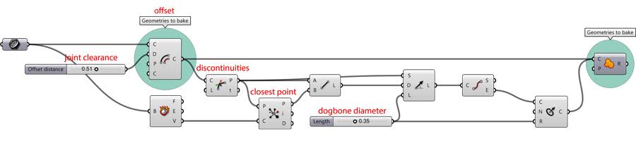
The next image explains how the clearance of the joints in order to attempt a pressfit is made with Grasshopper.
Here's in an image of a version of the definition I developed.
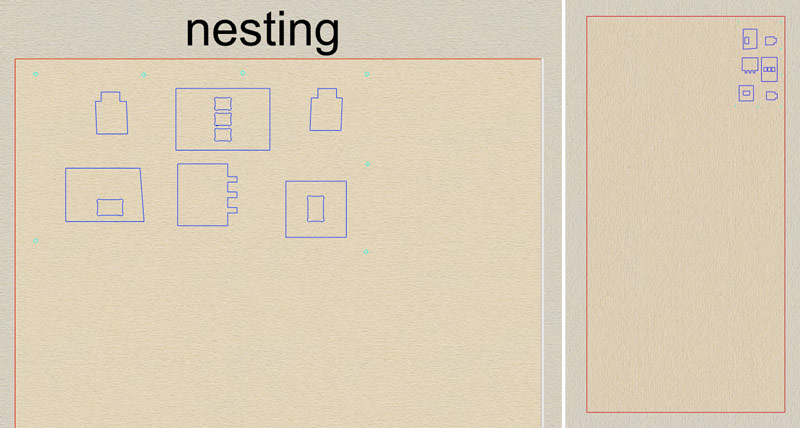
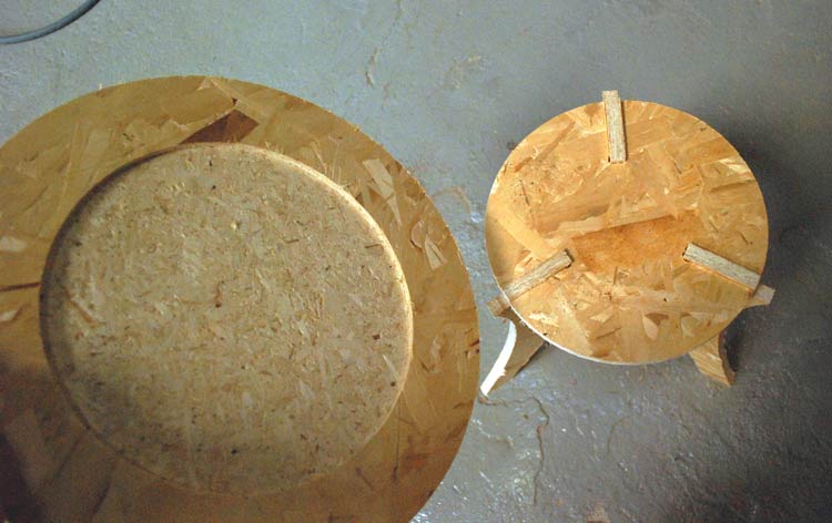
First nesting and joints test.
Round Stools and Table design.
I designed two 3-leg identical stools, which could serve as supports for a bigger table top.
The two main challenges were
1/ to solve the 3-leg joint,
2/ to find an efficient way for adapting the table-top on the stoold and
3/ to optimize the nesting of my pieces on the board.
Designing the stool.
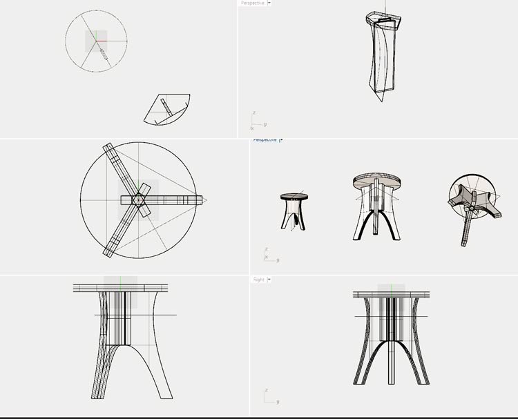
Two stools and a table top.
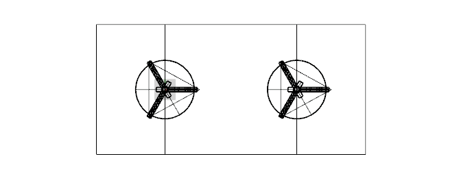
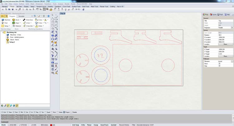
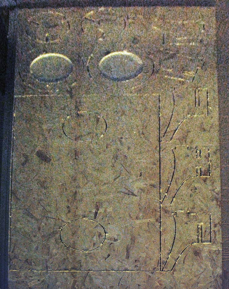
After designing my pieces, I used the Make2d command in Rhino, in order to take their blueprints.
I nested them in a square equal to the dimentions of my chipboard-to-mill and exported a .dxf file to Partworks.
Partworks is the CAM program I used for making my G-Code for the Precix milling.
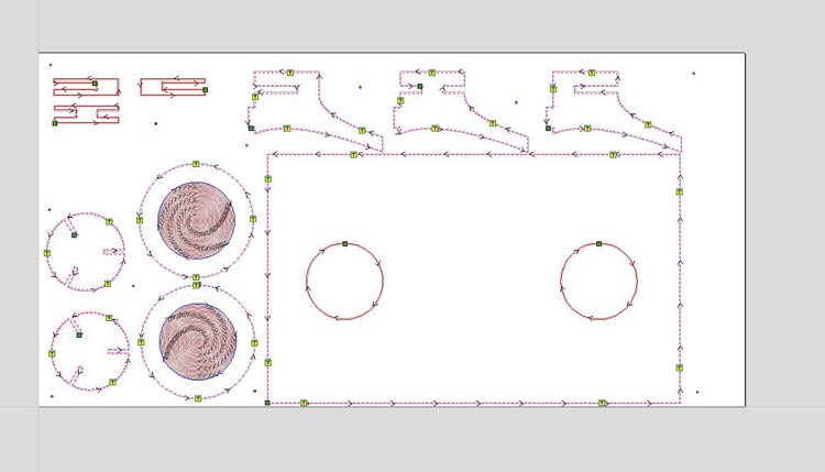
My pieces nested in the board, in Partworks.
Partworks process for Precix
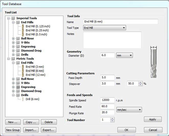
For the 2d cut, we go to Tool Database and Set Parameters.
Metric Tools - Endmill (6mm flat, endmill).
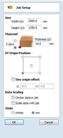
Set the size of the material I'm working with:
width: 2500 mm
height: 1250 mm
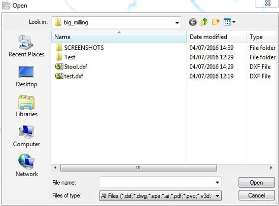
Import my rhino file: File menu > Import.
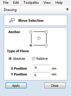
Next step is moving the anchor point to 0,0.
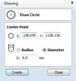
Then, create the holes for the screws.
Create vector > Draw circle
I gave a 6 mm radius diameter.
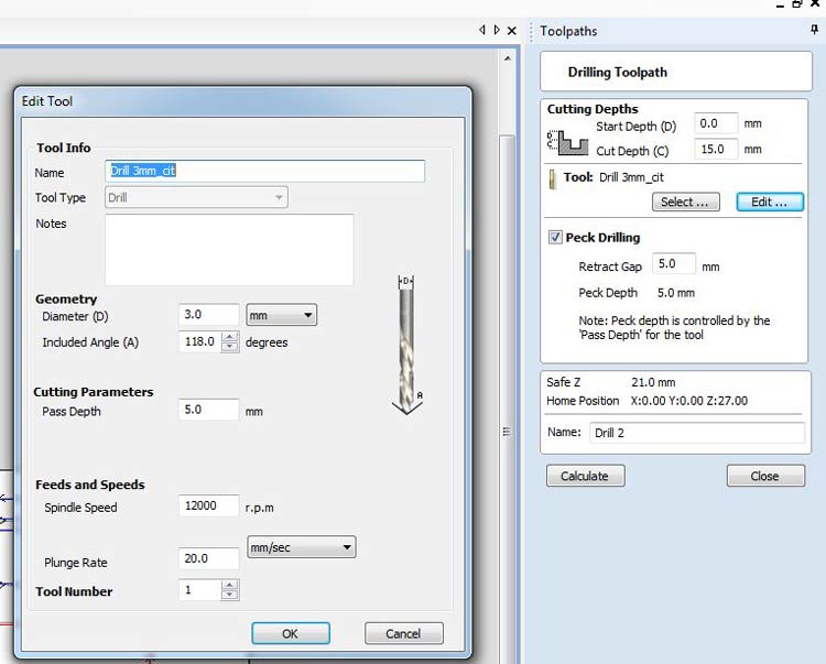
Under Toolpaths menu > Drill (double click).
Create Profile Toolpath: 2D Profile
Cut depth: start at 15mm.
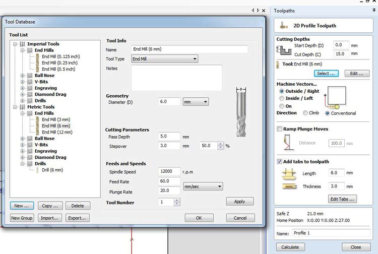
Next step is to set the machine vectors: outside/right
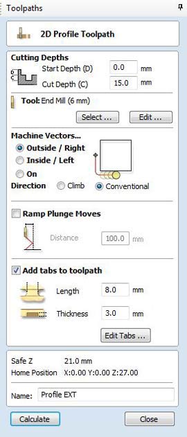
Add tabs: lenght (how long is the tab) 8 mm, and thickness of the tab 3 mm.
Tabs are useful because they keep the piece that is being milled in the right place, without them the pieces would move and they would get messed.
After this, go to Toolpath Menu > Toolpath Operations > Preview.
Save Toolpath, and PostProcessor
For the Pocket Toolpath we set the cut depth to 7.2 mm
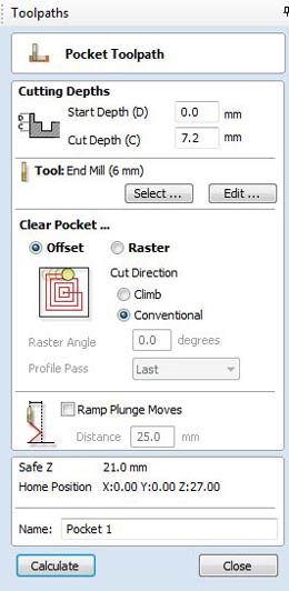
Setting the speed of the milling bit.
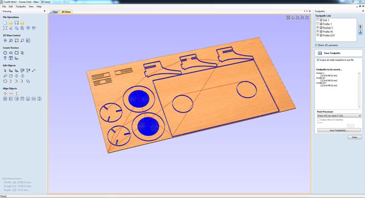
Finally, preview the milling process and export the G-code for loading into the Precix CNC controller.
Precix ATC Arc (in mm). Export Gcode.
We have two files to save: the Drill1.gc for the screws (run the first in order to place the screws on the right positions).
The Profile1.gc (the second one is for milling the actual pieces).
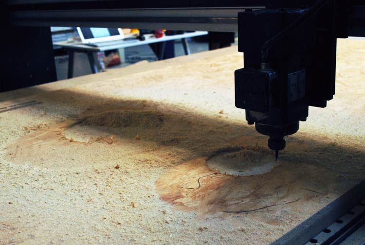
Milling process.
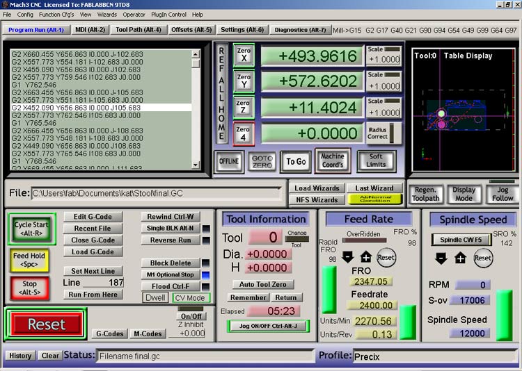
The G-code files should be loaded to the computer controlling the Precix.
On the left side you can see the G-code.
We move the x,y,z to 0.
SUPER IMPORTANT TIP! Taking a screenshot of the x,y,z coordenates right after setting the 0,0,0 and allowing to see the line numbers of the G-code is the only way to allow you to continue the process in case it stops for any reason. This happened to me 2 times because of problems of the machine. The first time I hadn't done that so I ruined the board and had to replace it before starting over again.
Put in place the milling bit.
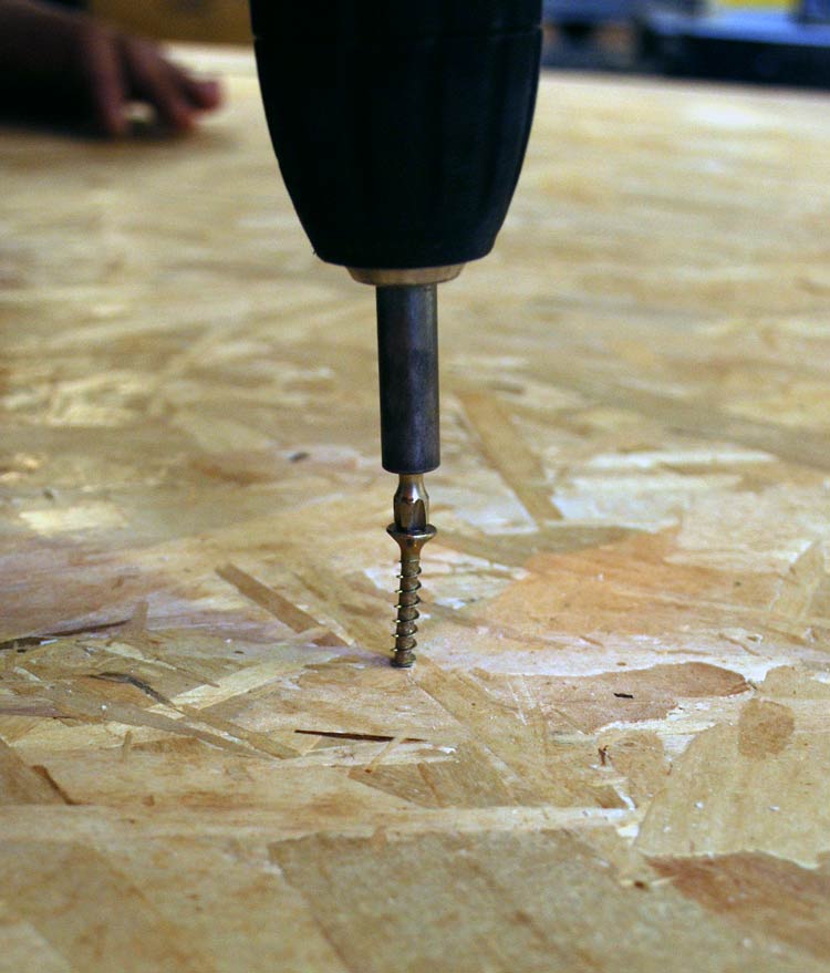
With the holes for the screws done by the CNC we go one by one and drill a screw inside of each one. With the 3 mm dirll bit and drill the the holes
We start the milling process of the whole board.
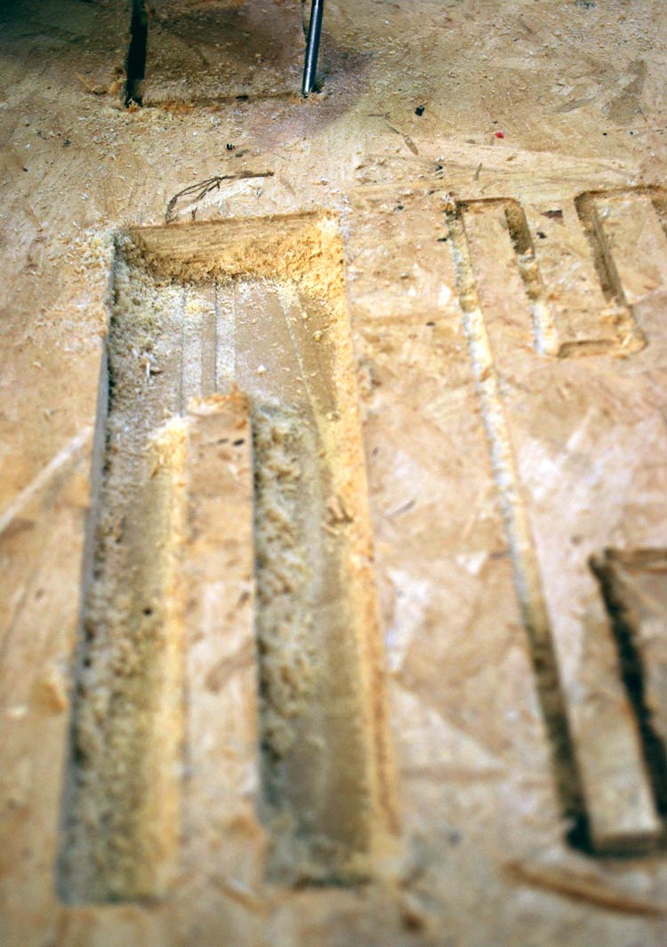
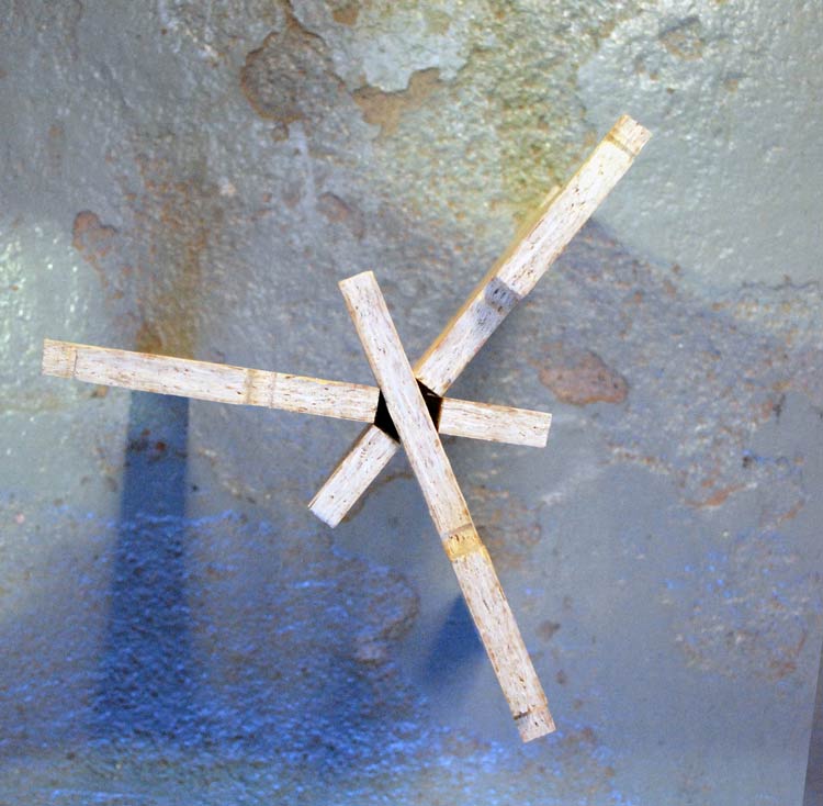
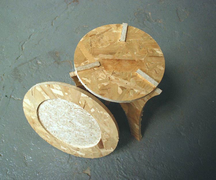
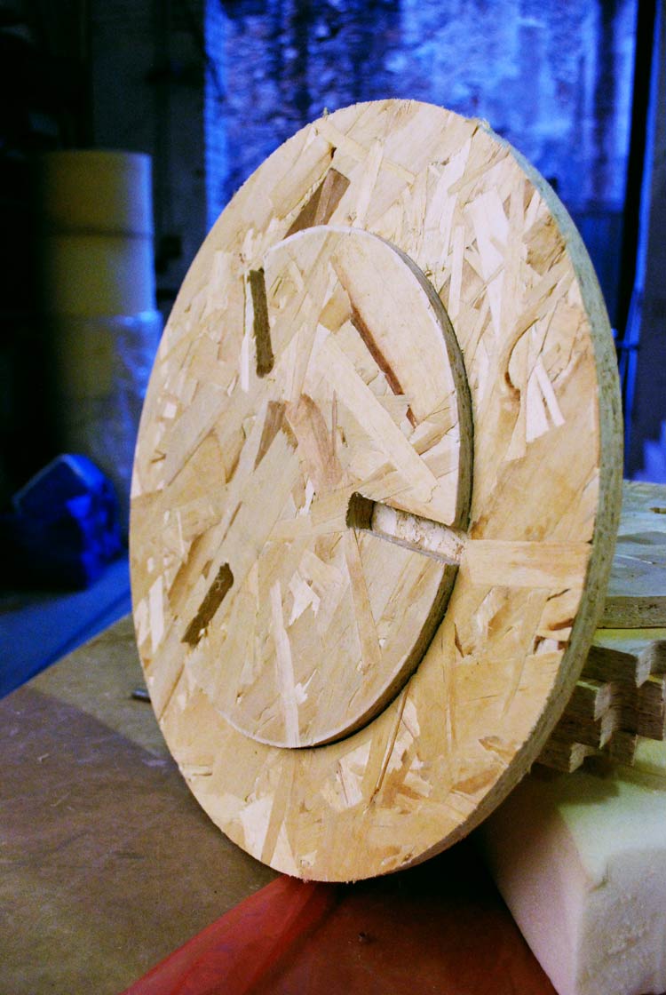
Those are the first assembly tests for the pressfit parts.
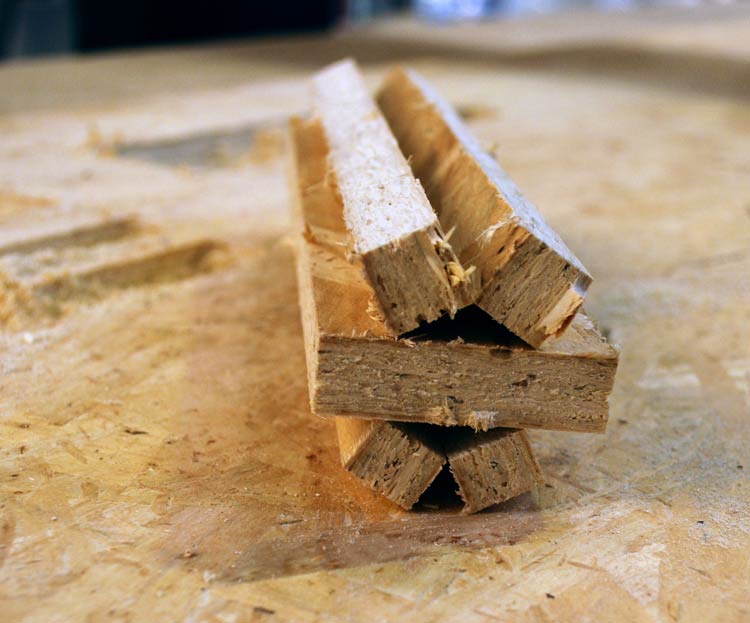
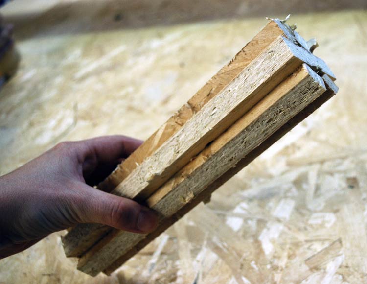
Is the test is succesful we can go on with the milling of the whole board.
Here is my board milled.
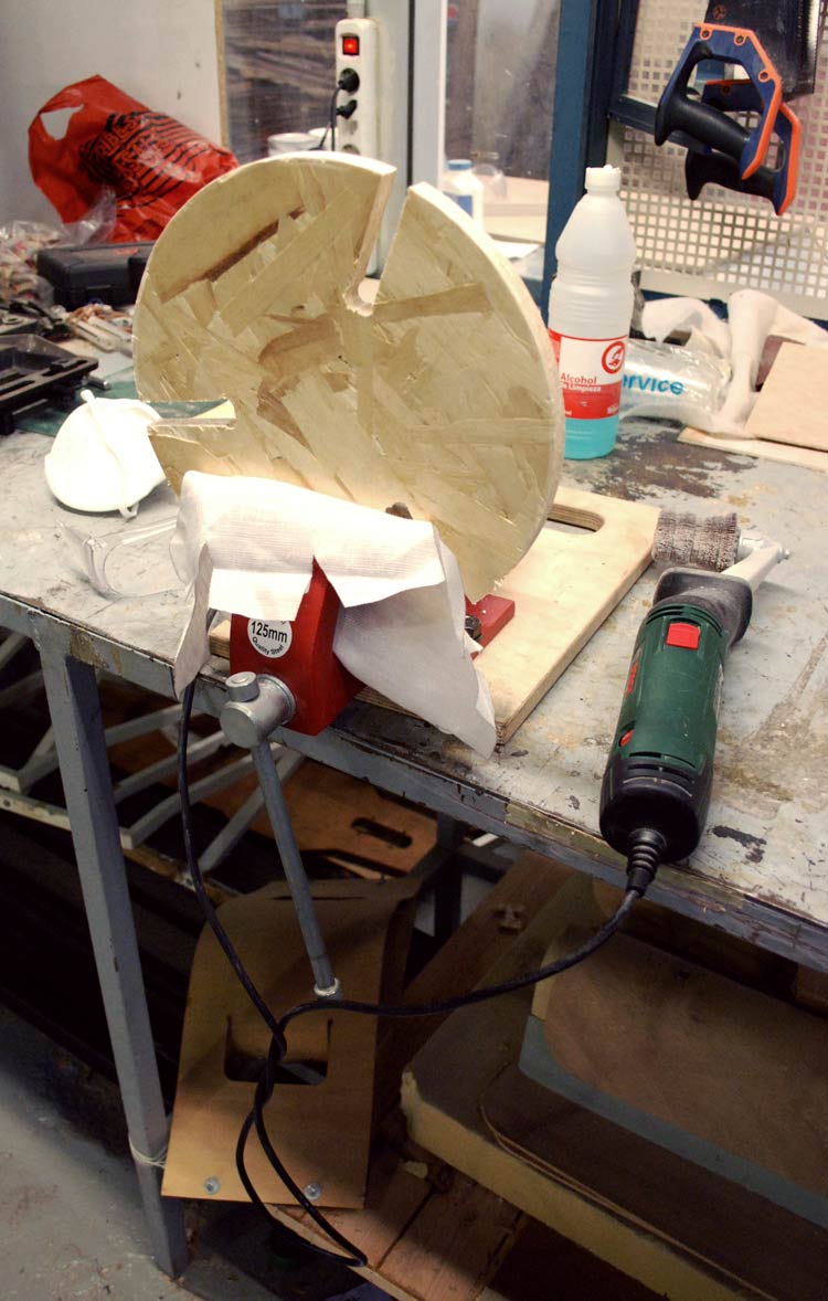
The first thing to do after that was to take out the part from the chipboard using a screwdriver and a small hammer.
Then, I sanded each piece in order to get rid of the spiky edges.
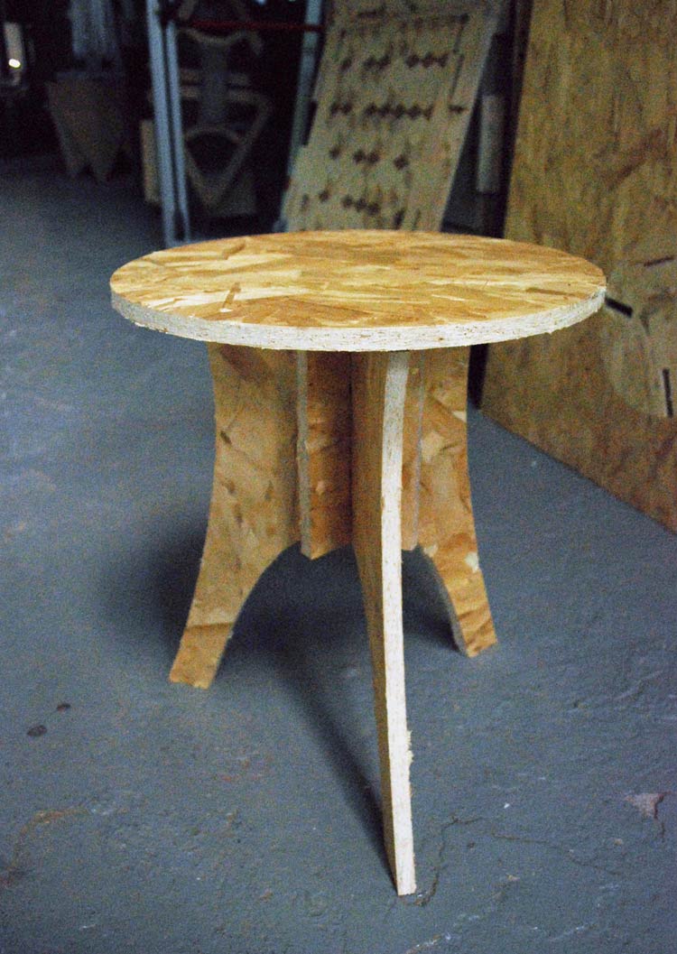
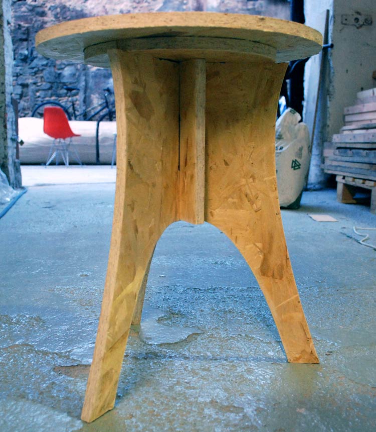
And after assembling the parts, I got my stool.
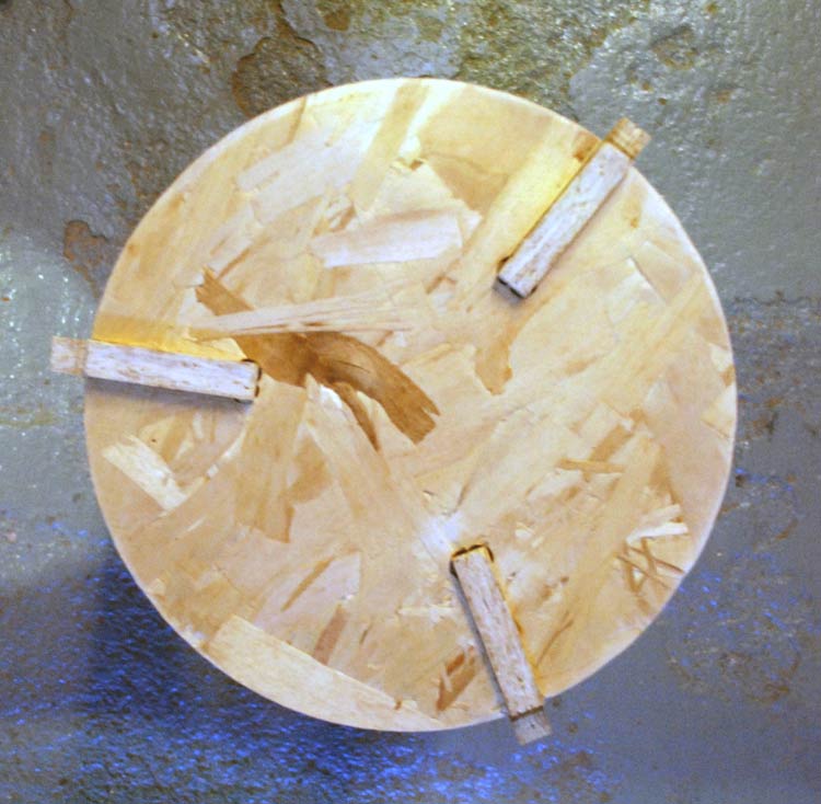
Here is my final piece of furniture.
All design and Partworks files developed this week can be found here.