This weeks goal was to mill a circuit board, solder the electronics and, finally, program it.
Milling the board turned out to be quite fun. Being my very first time to mill anything, even the slightest details in the process were quite a challenge for me.
Materials and machinery
-copper surface stock material -- should be bigger that the outline of the design
-double-sided tape
-alcohol to take out the grease
-Roland Modela
-1/64mm milling bit to mill the traces and pads of the circuit board
-1/32mm milling bit to mill the outline
-allen key to change the bit in the collet of the spindle
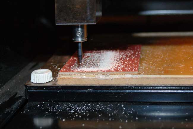
The first thing to learn was how to choose a PCB(printed circuit board) blank (FR-2) and place it on the sacrificial board of the milling machine. Currently MDF is used for this purpose but this will be changed for another PCB blank.
First comes checking for the slightest inclination in the copper surface, for it could easily make the whole process go wrong, as working on a circuit board requires precision in a scale of a tenth of millimeter (0.3-0.6).
To do so I used a square rule to check both directions of the pad and the diameter.
After checked, the copper is placed on the sacrificial board of the machine bed using double sided tape. It's crucial that it remains in place during the whole milling process.
Grease from the fingers should be removed from the metal surface before milling using alcohol.
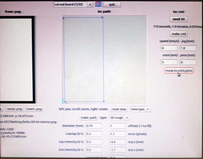
The next thing to do is to prepare the maching and synchronize its parameters / system of coordinates with those of the respective software used to run it.
My first try to mill a board was on a Roland Modela MDX-20 machine, using the FabModules software through the command line (sudo fab).
Calibrating the Machine and the CAM Software.
Toggling View allows you to access the stock or fix the mill bit into the collet of the spindle. Using the buttons on the machine it's easy to change between the Home and View positions.
Setting the Home position
The first thing to do is set the 0,0,0 point of the machine, corresponding to the start of our job.
Setting the x0,y0 coordinates in the control software of FabModules means moving the tip (numerically). By releasing slightly the skrew until the bit touches the surface of the board and the fasten the skrew again using the allen key.
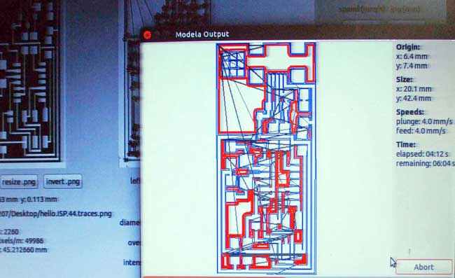
Following the steps of the FabModules tutorial run through the command line both helped me generate the .rml files for milling the board and control the Modella MDX-20 machine. FabModules run through the browser can only generate code.
The files used for milling and programming the FabISP are found here.
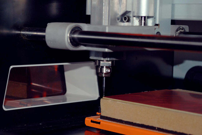
My first milling experience was (almost) a disaster.
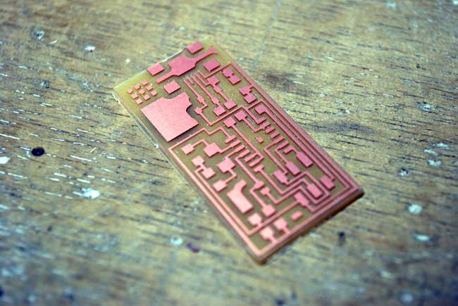
The traces were finely milled, however, the 1/32mm bit was not properly fixed, causing it to drop and cut the board in two.
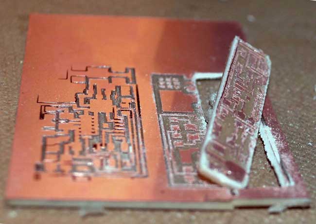
Troubleshooting the process allowed me to go throught the same steps correctly and mill my board properly.
Soon, the board was finely milled.
Having a second milling machine in the lab allowed us to go through the whole process again and figure out the apparent differences between different hardware and software. In the same time, trying to mill on a another machine using the same bits made apparent the different milling qualities. My third mill on a Monofab SRM-20 machine gave a lower quality mill, which I used to improvise on soldering for the first time.
[Note that on the Monofab SRM-20, when z(0) of the machine is equal to z(0) set in the software is a singularity, therefore the machine is unable to process the given data. The z-safe height of the software should be altered.]
Soldering.
One of the most important advices I received while learning how to solder was to treat soldering like water. The whole process turned out to be quite fan.
First of all, I cleaned the board from copper hair, remaining from the milling process.
The second step was to cover the suface with flux, the paste that attracts the soldering tin on the coper surfaces.
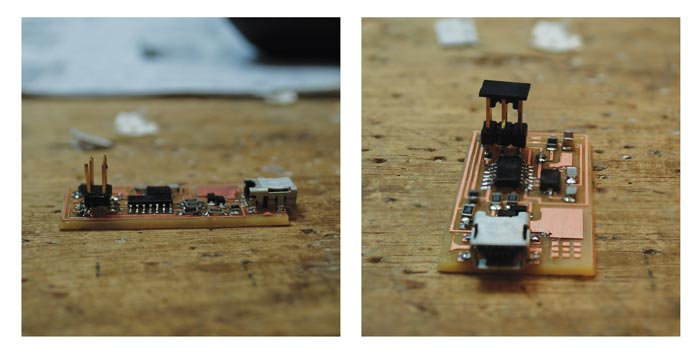
Using the iron for the first time was quite exciting. It requires a lot of attention as well as firm and quick moves. Typically it's important to start from the most difficult parts, such as the miniUSB and the microcontroller and continue with the smaller to the bigger ones, from the center towards the outline.

I used the multimeter to check the connections of the circuit. I resoldered the components where needed.
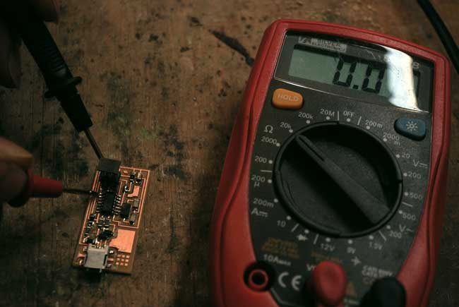
In the same time, it's quite crucial to solder the right components - but I'll come back to that later.
Programming the Programmer.
Following the Programming tutorial for Windows guided me through the whole process. However, there were extra things needed to be done in order to get to program the board.
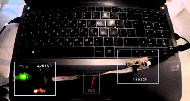
Plugging the FabISP and WinAvr into the computer in order to program it.
The first thing to do was to locate and note the current system path.
Trought R-clicking on My Computer>Properties>Advanced System Settings>Environment Variables I was able to find and copy the paths both for User and System Variables in a .txt file.
After downloading and installing (through the console) the WinAVR Software I checked and found out it had broken my paths. To solve this I copied and pasted the pre-existing paths adding C:\WinAVR-20100110\utils\bin at the end, locating my WinAvr binary folder.
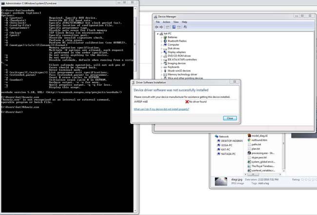
The second problem I faced while following the tutorial had to do with finding and installing the drivers for Windows 7. In the tutorial there was only a link to Win-8 drivers download, therefore I had to search for the Win-7 drivers. I found them here and installed them. Still, my computer couldn't recognize the FabISP.
After that I thought it would be easy to program the board following the rest of the instructions but it turned out that I had to go back to the previous step of soldering and checking the components on the circuit with multimeter.
In lab, the box of 1KΩ resistors were mixed with OΩ resistors, causing difficulties in finding the error while trying to program the board. Quite simple it may seem, thought the slighest mistake in this process of picking the components from their boxes and soldering them can cause a lot of trouble after it's been put in the board.
In order to be sure that the problem I faced was related with the board, I tried going through the whole process on Linux. Error 1 kept coming up.
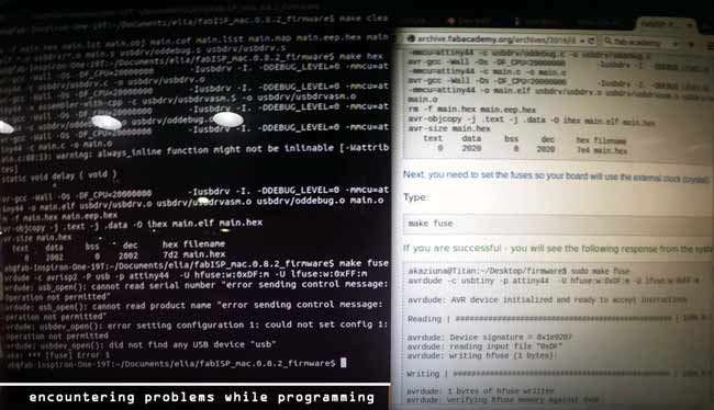
It required quite a few measurements, re-soldering and taking out 2 components to be able to program the board.
Finally, I made it - this time on a Mac, following the respective instructions- as it turned out the whole process it a lot more simple than it is on Windows 7 or 8.