As an output I'm making an LED array. My intention was to design my board in two parts which can be assembled with wires:
-the avr part, and
-the LED array.
I was thimking to keep them separate in order to try later and load different programs for my LED array using my Fabduino.
I started trying to understand the given board examples (1) (2) and at the same time searching online in order to understand the strategy of assembling and programming LED arrays.
Soon I understood that there were two ways to do that: multiplexing and charlieplexing. One of the most straightforward explanations I found were the following:

Tutorials:
- 4x3 array : http://smokespark.blogspot.com.es/2013/08/32-charlieplexing-4-x-3-led-array.html
- 5x4 array : http://www.instructables.com/id/Controlling-20-Leds-from-5-Arduino-pins-using-Cha/step2/Charlieplexing-The-theory/
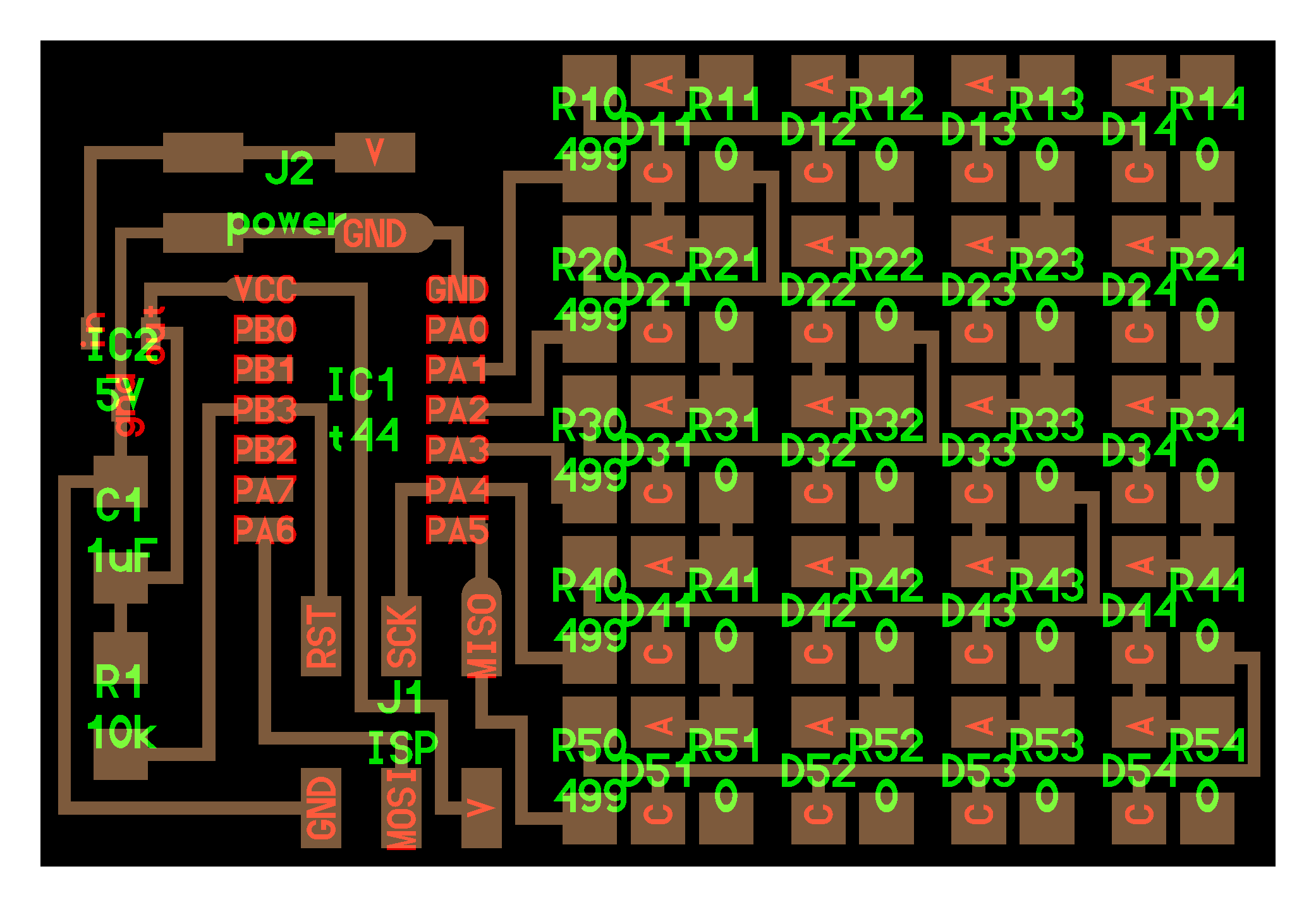
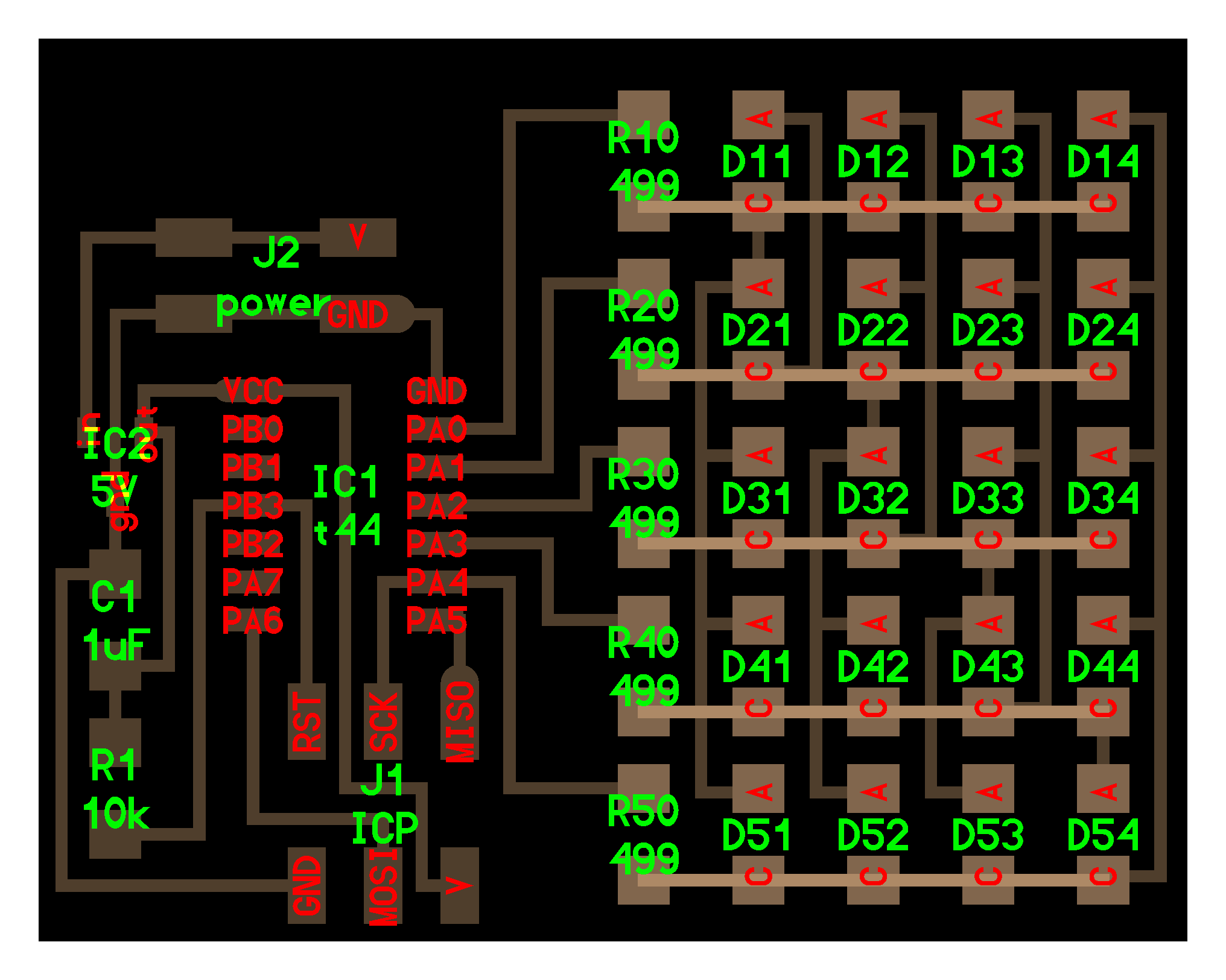
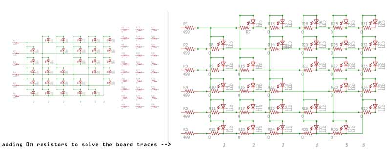
After hours of looking at other array schematics and sketching circuits, I tought I was able to design my own 6x5, 30 lED array. The problem with that would be that I wouldn't be able to use the given C code, but I 'm sure that I'll manage to program it from the Arduino.
Starting with Eagle
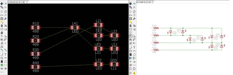
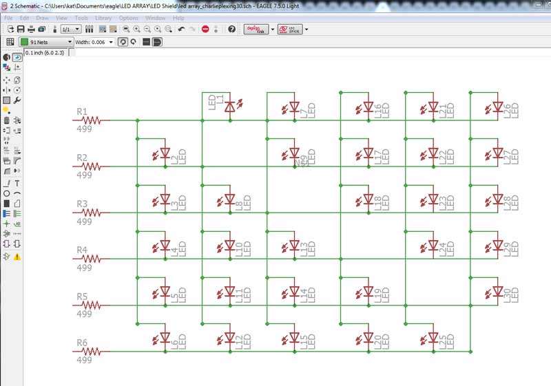
In order to solve the traces on the board, I added 30 0Ω resistors to my schematic.
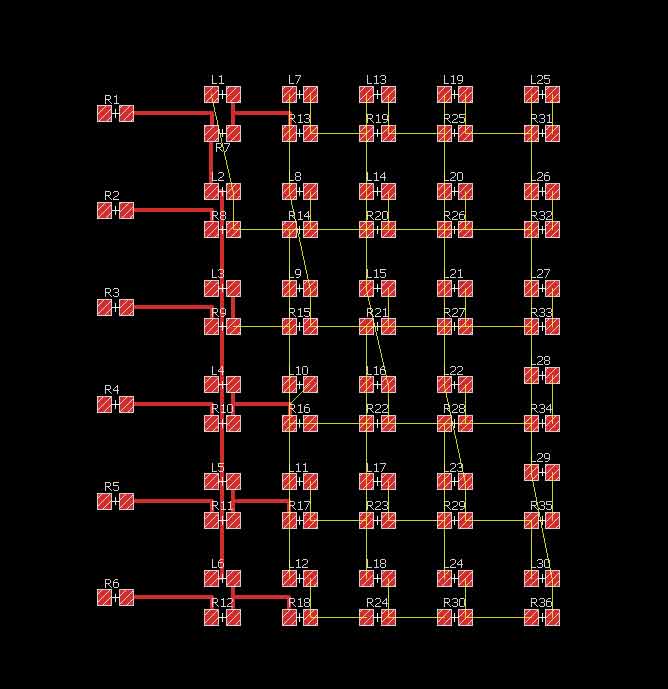
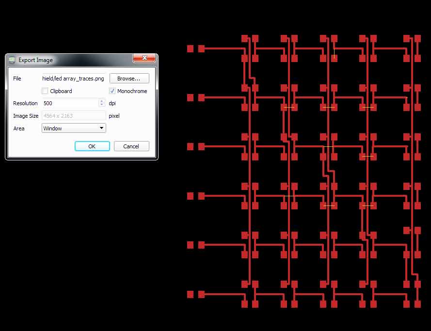
After solving my array schematic and board on Eagle, I decided to work on the Traces and Outline I would mill in other modelling environments, in order to treat my board as a design object more freely. For this purpose I used Inkscape, Rhino, Illustrator and Photoshop.
After exporting my monochrome images, I imported them in Inkscape in order to trace the outlines as vectors.
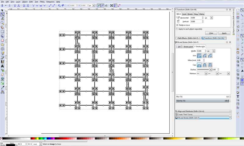
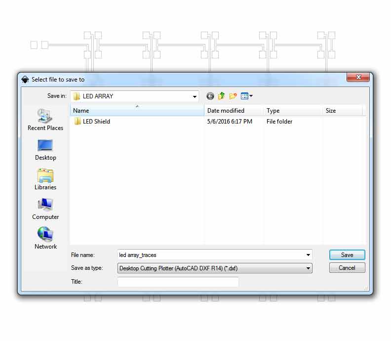
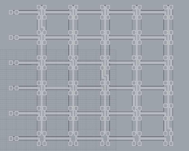
I exported the file as .dxf and imported it on Rhino for modelling the array.
In Rhino it was easy to work on the geometry. I insisted in designing an equal LED distance array. The very first thing to do was to join the traces' vectors and keep them on a separate layer.
I designed the 3D of my desired object.

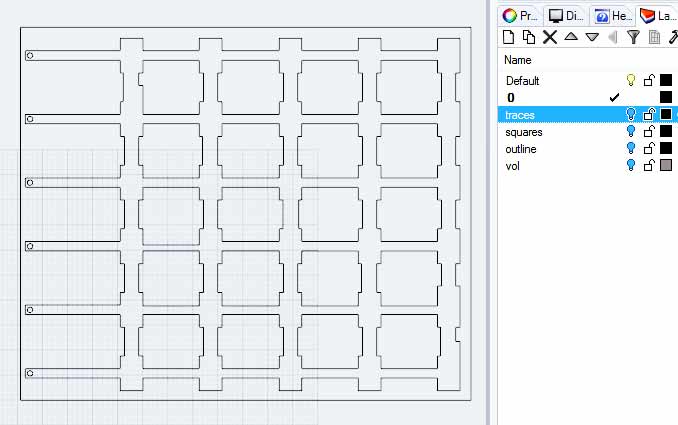
Also, I divided my design in layers according to the demands of the milling process. This way it would be possible to prepare the final files for the traces and the outlines. In the picture below is shown my desired array outline, with the parts to remove between the LEDs.
I exported the model (File>Export Selected) as .pdf, paying attention to keep the 1:1 ratio between the model and pdf units.
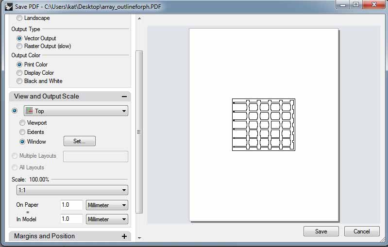
Then I imported the .pdf in Illustrator. With Illustrator I worked on the lineweights for my paths to mill, making a 5mm offset so that I was sure the drill bit wouldn't mill on my pads.
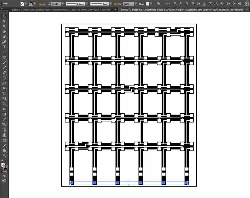
Milling and Soldering
I prepared the final files of the traces and outline to mill in Photoshop. The files can be found here.
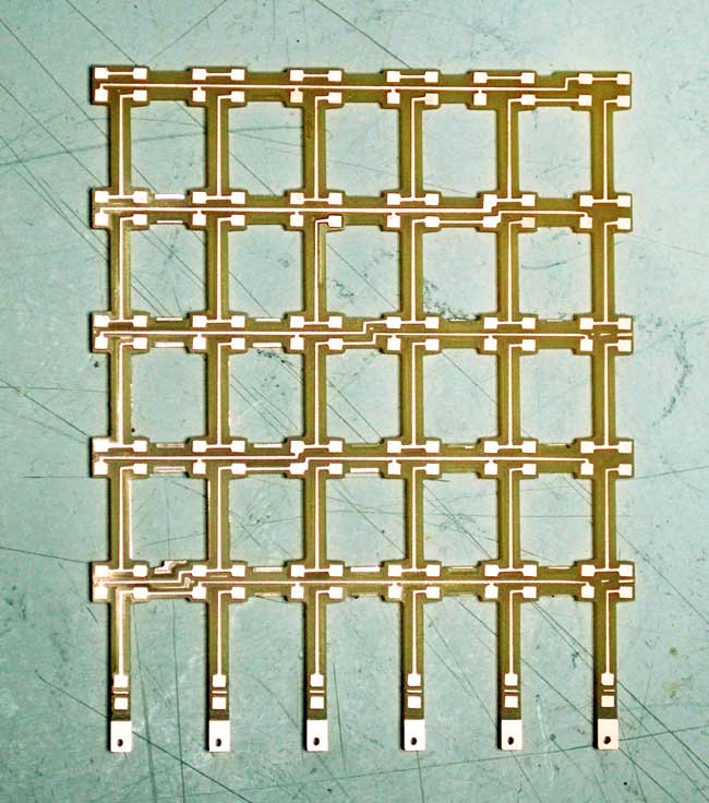
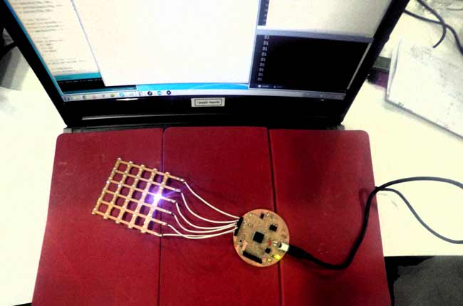
After patiently soldering it...
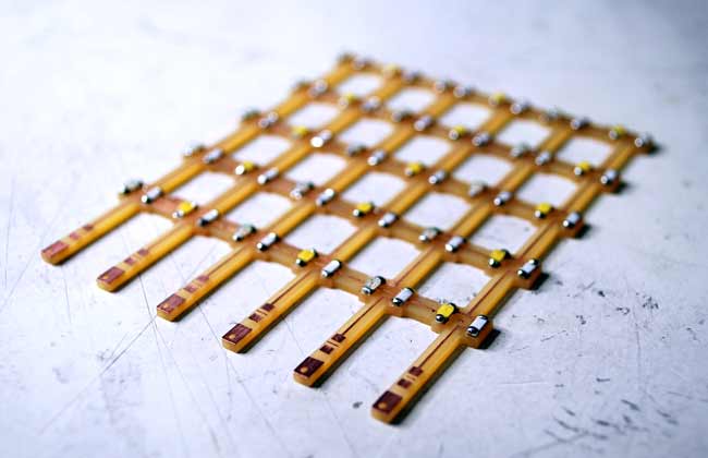
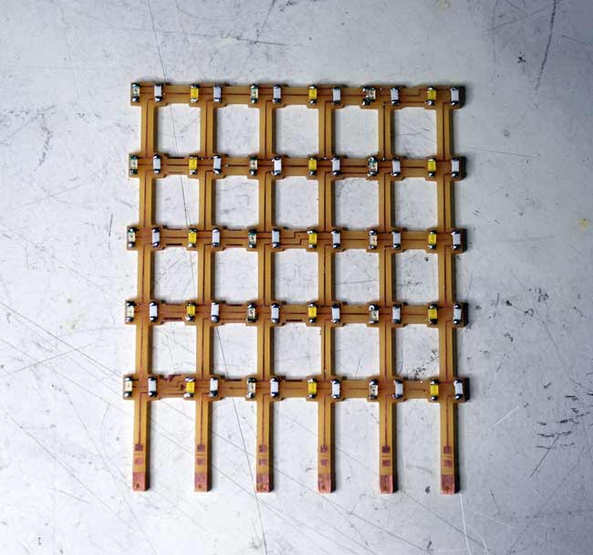
I soldered cables and connected it to the analog pins of my Circulino (my fabbed Leonardo).
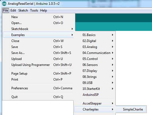
At first, I programmed the array using the Simple Charlie from Examples >> Chalieplex on the Arduino IDE and altered it in order to check if my LEDs worked.
My final code was the following.
                            #include

                            //define pins in the order you want to address them
                            byte pins[] = { 10, 9, 8, 6, 12, 4};

                            //initialize object
                            Charlieplex charlieplex = Charlieplex(pins, 6);

                            //individual 'pins' , address charlieplex pins as you would adress an array
                            charliePin ledA1 = {
                              1, 0 };
                            charliePin ledA2 = {
                              2 , 0};
                            charliePin ledA3 = {
                              3, 0};
                            charliePin ledA4 = {
                              4, 0 };
                            charliePin ledA5 = {
                              5, 0 };


                            //individual 'pins' , address charlieplex pins as you would adress an array
                            charliePin ledB1 = {
                              0, 1 };
                            charliePin ledB2 = {
                              2, 1};
                            charliePin ledB3 = {
                              3, 1};
                            charliePin ledB4 = {
                              4, 1 };
                            charliePin ledB5 = {
                              5, 1 };

                            //individual 'pins' , address charlieplex pins as you would adress an array
                            charliePin ledC1 = {
                              0, 2 };
                            charliePin ledC2 = {
                              1, 2};
                            charliePin ledC3 = {
                              3, 2};
                            charliePin ledC4 = {
                              4, 2 };
                            charliePin ledC5 = {
                              5, 2 };

                            //individual 'pins' , address charlieplex pins as you would adress an array
                            charliePin ledD1 = {
                              0, 3 };
                            charliePin ledD2 = {
                              1, 3};
                            charliePin ledD3 = {
                              2, 3};
                            charliePin ledD4 = {
                              4, 3 };
                            charliePin ledD5 = {
                              5, 3 };

                            //individual 'pins' , address charlieplex pins as you would adress an array
                            charliePin ledE1 = {
                              0, 4 };
                            charliePin ledE2 = {
                              1, 4};
                            charliePin ledE3 = {
                              2, 4};
                            charliePin ledE4 = {
                              3, 4 };
                            charliePin ledE5 = {
                              5, 4 };


                            //individual 'pins' , address charlieplex pins as you would adress an array
                            charliePin ledF1 = {
                              0, 5 };
                            charliePin ledF2 = {
                              1, 5};
                            charliePin ledF3 = {
                              2, 5};
                            charliePin ledF4 = {
                              3, 5 };+
                            charliePin ledF5 = {
                              4, 5 };


                            void setup(){
                            }

                            void loop(){
                              charlieplex.clear();


                            //  charlieplex.charlieWrite(ledA1,HIGH);
                            //  charlieplex.charlieWrite(ledA2,HIGH);
                             // charlieplex.charlieWrite(ledA3,HIGH);
                             charlieplex.charlieWrite(ledE1,HIGH);
                              //charlieplex.charlieWrite(ledA5,HIGH);
                            //
                            //  charlieplex.charlieWrite(ledB1,HIGH);
                            //  charlieplex.charlieWrite(ledB2,HIGH);
                            //  charlieplex.charlieWrite(ledB3,HIGH);
                            //  charlieplex.charlieWrite(ledB4,HIGH);
                            //  charlieplex.charlieWrite(ledB5,HIGH);
                            //
                            //  charlieplex.charlieWrite(ledC1,HIGH);
                            //  charlieplex.charlieWrite(ledC2,HIGH);
                             //charlieplex.charlieWrite(ledC3,HIGH);
                            //  charlieplex.charlieWrite(ledC4,HIGH);
                            //  charlieplex.charlieWrite(ledC5,HIGH);
                            //
                            }
>>In the Interface (week 16) assignment, I 'm providing an alternative code, as well as a Processing interface from which I control the array.
The files for the output assignment can be accessed here.