Introduction


Fab2D2 is a differential robot designed to help for move small objects into the laboratory. The robot has implemented the line follower sensing system to move autonomously. The robot can carry maximum 10 lbs. Each moment that the robot moves, it emits a warning sound.

The robot has two working modes: first, in "AUTONOMOUS MODE" the robot follows black line. When the robot finds a cross it stops for five seconds for that people put or remove objects.

Second the robot can be manipulated remotely from a smartphone using bluetooth communication. When the communication is enabled the user can monitore battery level and erros information such as obstacles in front of the robot. The user also can use the cellphone as remote control for move the robot. This is the "MANUAL MODE".

The robot has some input devices such as battery level sensor, distance sensors, infrarred sensor and capacitive touch buttons. The output devices of robot are motors and a buzzer. The main processor is ATMEGA328P and runs at 20MHz.

You can see a summary slide here or an video presentation here where you can see the features of the robot.


Bill of Materials

For this project is necessary this materials:

      - 600x300mm white acrylic plate of 3mm.

      - 600x300mm blue acrylic plate of 6mm.

      - White PLA

      - Wax molding

      - 8 screws and nuts M4

      - 6 screws and nuts M2

      - 8 screws M3

      - 160mL Rubber Compound PMC 121/30

      - Cooper board

      - Atmega328P

      - 5 phototransistors OP580DA

      - Ultrasonic sensor HC-SR04

      - Bluetooth module HC-06

      - 4 Motors Jameco 253471

      - 2 Motor drivers A4952-3

      - Lipo Battery 11.1V

      - Buzzer

      - Other components (R, C, Leds, etc)

Mechanical Design


Mechanical parts of Fab2D2 were designed in SolidWorks. You can donwload files here: back, chassis, cover, front, grips, molding, ring, side, support, assembly.


For machining every mechanical parts, I used next processes:


Computer Controlled Cutting

Chassis, sides, grips and cover of Fab2D2 were cutted with Epilog Zing 16 Laser.


Chassis

The chassis is a 6mm blue acrylic and the values for cut are Speed: 10, Power: 100 and Frequency: 5000.

Before to cut the chassis is necessary to has cutted sides and printed front and back parts becouse is important to know the dimensions of holes. I recommended to consider 0.2mm of laser kerf. The chassis file is a parametric design and you can edit the dimension of holes, for example I set sides holes by 14.60mm X 2.55mm and front and back holes by 14.95mm X 3.95mm.


Sides and Grips

Sides and grips are 3mm white acrylic and the values for cut are Speed: 20, Power: 100 and Frequency: 5000.

You must cut two sides and two grips


Cover

The cover is a 3mm white acrylic and the values for cut are Speed: 20, Power: 100 and Frequency: 5000.

Before to cut cover is necessary to has cutted grips becouse is important to know the dimensions of holes. I recommended to consider 0.2mm of laser kerf. The cover file is a parametric design and you can edit the dimension of holes, for example I set grips holes by 19.60mm X 2.60mm.


3D Printing

Front, back, rings and support for motors of Fab2D2 were printed with Dimension 1200es.


Front


Back


Rings and Supports

The rings and supports was designed for Jameco 253471 Motor.

You must to print four rings and four support for motors.


Molding and Casting

Wax moldings of wheels of Fab2D2 where machining using Roland MDX-540.


Wax molding

For create the g-code for machine I used SRP Player software and I used a 1/8'' square tool. Before machining is necessary to calibrate Z origin. You can donwload rough and finish files here.

After machining the mold, you need to mix rubber, I used Liquid Rubber Compound PMC 121/30, and I added black color. Every mold needs approximately 20mL of rubber.

Lubricate the walls of mold, put the ring and pour the rubber. I recommended to use syringe for pouring the rubber.

Wait 4 hours and remove the wheel of the mold and dry it for one day.


These are all mechanical parts of Fab2D2, next you can see some pictures of assembly:

Electronic Design


Electronics PCBs were designed in EAGLE. You can donwload files here: control pcb, input-output pcb, line sensor pcb, ultrasonic pcb.

All PCBs were machining using Roland MDX-540. Every PCB has a vinyl mask for protect cooper traces. The vinyl mask was cutted using Roland GX-24 cutter.

Next, you can see every PCB development:


Control PCB

Control PCB is the main board of Fab2D2 becouse it has the micrcocontroller to process the data from inputs and control the outputs. This PCB has headers for conect inputs and outputs. You can see extra information on input devices week and output devices week

The control PCB has a linear regulator and reverse current protection. Fab2D2 can be energized from 7v to 12v and need aroud 800mA when motors are at maximun speed.


Line Sensor PCB

Line sensor PCB has five phototransistors and five leds. Phototransistors detect the relfected light on the floor emitted by the Leds.


Ultrasonic Sensors PCB

Ultrasonic sensors PCB has two headers for connect two ultrasonic and has one header for connect it with Control PCB.


IO PCB

IO PCB has two capacitive touch buttons, one buzzer, three Leds. One Led is blue and indicate the power (on/off), the other leds are oranges and indicate the mode of working of Fab2D2.


These are all PCBs of Fab2D2, next you can see some pictures of connections:

Programming


Embedded Programming

I used Arduino IDE for programming the control PCB. You can donwload files here: Control pcb programming, Input-output pcb programming, Ultrasonic pcb programming.


Control PCB programming files are in control.rar, in this compressed file you will find three files:

    - Config.h, in this file you can change pinout and some constants for example the time of beeper.

    - Control.h, in this file you will find core functions to control the robot, you should't changue this file.

    - control.ino is the Arduino file programming.

For upload the programm in ATMEGA328P you must extract and copy fab2d2 folder in hardware folder of Arduino preferences path. Next, restart Arduino, select "fab2D2" as board and set clock as "20 MHz (external)".


IO PCB programming file is io.ino file. For upload the code in ATtiny45 you must select "ATtiny" as board and, "ATtiny45" as processor and set clock as "8 MHz (internal)".


Ultrasonic Sensors PCB programming file is ultrasonic.ino file. For upload the code in ATtiny44 you must select "ATtiny" as board and, "ATtiny44" as processor and set clock as "8 MHz (internal)".


The robot has three modes of working, the user can switch working mode by pressing the SET button, if the user press the button for more than one second, the robot executs the working mode selected. Next, each working mode is explained quickly:


Calibration Mode

In this mode the robot moves forward and takes 300 samples of each line sensor for find minimun and maximun values. These values are stored in eeprom memory.

void runCalibrationMode(){
  setSpeed(127, 127);
  calibrateLineSensors(300);
  stopMotors();
  saveCalibration();
}		
		

Autonomous Mode

In this mode the robot finds its position with respect to the black line and executs a proporcional-derivative (PD) control to stay on it, thus gets to move aotonomously. When the robot reaches an intersection it stops for 5 seconds.

void runAutonomusMode(signed int speedMin, signed int speedMax){
  unsigned int sensors[5];
  signed int ev=0, cv=0, dv=0, lastError=0;
  signed int speed = speedMin;
  
  resetPD(&ev, &cv, &lastError);
  
  while(isButtonOff() && mode==AUTONOMUS_MODE){
    runBeeperService();
    runDataOutService();
    
    if(checkError()) break;

    ev = getLinePosition(sensors);    

    if(sensors[0]>500 && sensors[4]>500){
      if(runAutonomousParking()){
        resetPD(&ev, &cv, &lastError);
        speed = speedMin;
        continue;    
      }
      else
        break;
    }

    PD(&ev, &cv, &lastError, speed, 5, 100);
  
    if(cv > 0)  setSpeed(speed, speed-cv);
    else        setSpeed(speed+cv, speed);
    
    if(speed < speedMax)  speed++;
  }

  stopMotors();
}		
		

Manual Mode

In this mode the robot waits until a command has been send trought serial port. The robot executs only next comands :

    f : move forward

    b : move backward

    l : turn left

    r : turn right

    L : fast turn left

    R : fast turn right

    s : stop

void runBluetoothMode(signed int speed){
  char data = 0;
  
  while(isButtonOff() && mode==BLUETOOTH_MODE){
    runDataInService(&data);
    
    switch (data){
      case 'f':
        setSpeed(speed, speed);
        break; 
      case 'b':
        setSpeed(-speed, -speed);
        break;
      case 'l':
        setSpeed(speed/2, speed);
        break;
      case 'r':
        setSpeed(speed, speed/2);
        break;
      case 'L':
        setSpeed(-speed, speed);
        break;
      case 'R':
        setSpeed(speed, -speed);
        break; 
      case 's':
        offMotors();
        break; 
    }
    
    runDataOutService();
    
    if(data=='f' || data=='l' || data=='r' || data=='b') runBeeperService();
	else digitalWrite(SPK, LOW);
  }
  
  offMotors();
}		
		

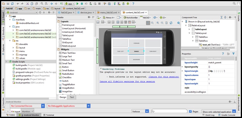
Application Programming

I used Android Studio for developed the App. You can donwload apk files here: App, Android Studio project.


Next, I'll show the features of the app:


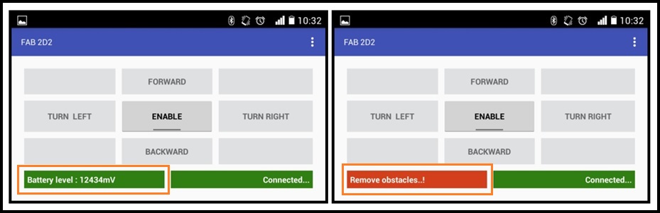
Real time sensor monitoring

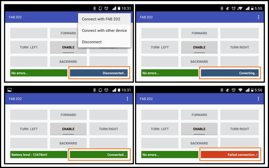
Real time connection monitoring

Bugs reporting

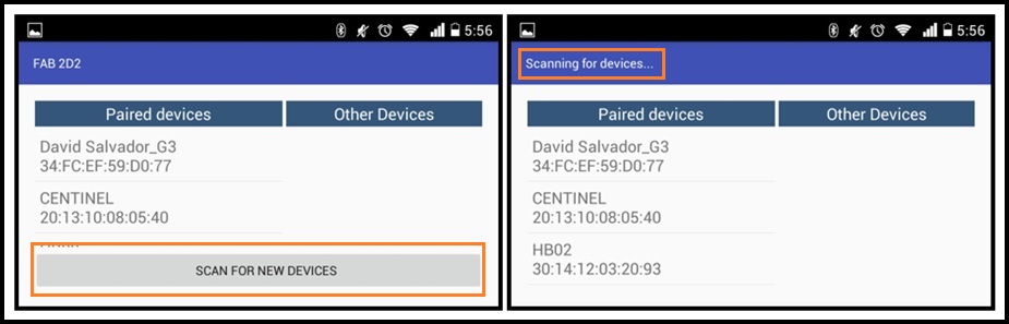
Bluetooth devices scan


Questions, Videos and Downloads


What is the deadline? How much time do I have left? What task have been completed and wath task remain? How will I complete the remaining tasks in time?

This questions are not necessaries for my project becouse all tasks have been completed at time.


What has worked? And what hasn't?

All systems of my project works perfectly. At the begining I have some problems with line sensors but I implemented a calibration for solve it. This calibration is based on Pololu 3pi Robot algorithm.


What questions still need to be resolved?

An important question to solve is the durability of the robot structure with heavy loads, this question will only be resolved in the course of time.


What have you learned?

I have learned 3D design and improve my habilities for make moldings.


Calibration Mode

>

Autonomous Mode

Manual Mode


Links

Final project files :

      - Presentation (.png) : https://archive.fabacademy.org/...

      - Presentation (.mp4) : https://archive.fabacademy.org/...

      - Mechanical design files :

            * Back (.sldprt) : https://archive.fabacademy.org/...

            * Chassis (.sldprt) : https://archive.fabacademy.org/...

            * Cover (.sldprt) : https://archive.fabacademy.org/...

            * Front (.sldprt) : https://archive.fabacademy.org/...

            * Grips (.sldprt) : https://archive.fabacademy.org/...

            * Molding (.sldprt) : https://archive.fabacademy.org/...

            * Ring (.sldprt) : https://archive.fabacademy.org/...

            * Side (.sldprt) : https://archive.fabacademy.org/...

            * Support (.sldprt) : https://archive.fabacademy.org/...

            * Assembly (.sldasm) : https://archive.fabacademy.org/...

            * Molding machining files(.rar) : https://archive.fabacademy.org/...

      - Electronic design files :

            * Control PCB files (.rar) : https://archive.fabacademy.org/...

            * Input-Output PCB files (.rar) : https://archive.fabacademy.org/...

            * Line sensors PCB files (.rar) : https://archive.fabacademy.org/...

            * Ultrasonic PCB files (.rar) : https://archive.fabacademy.org/...

      - Programming files :

            * Control PCB Programing files (.rar) : https://archive.fabacademy.org/...

            * Input-Output PCB Programing (.ino) : https://archive.fabacademy.org/...

            * Ultrasonic PCB Programing (.ino) : https://archive.fabacademy.org/...

            * Hardware in Arduino files (.rar) : https://archive.fabacademy.org/...

            * App installer (.apk) : https://archive.fabacademy.org/...

            * App project (.rar) : https://www.dropbox.com/...


Creative Commons License

This work is licensed under a Creative Commons Attribution-NonCommercial-ShareAlike 4.0 International License.