A real experiencie of tridimentional drawing
(+)
I´ve been interested in a problem that I found during the time that I’ve been studying graphic and industrial design since 2010. In the entire career they teach us about 2D and 3D principles to apply in product design. But some of my friends had problems with 3D thinking. Actually, at the beginning the stage to get used to draw 3D objects is a 2D sheet of paper, later you get in 3D digital drawing using a computer to understand tridimensional geometry in a “flat screen”. But, what if we just learn 3D geometry in the same reality that involves us?
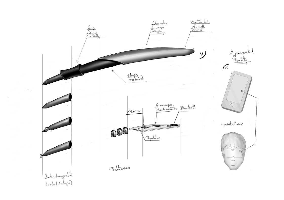
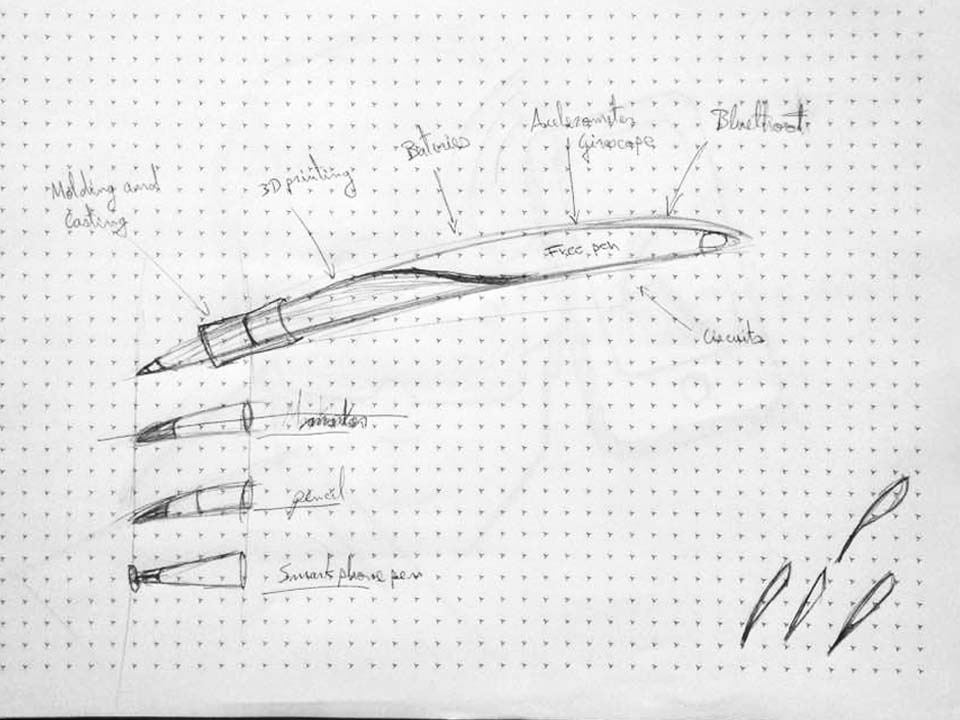
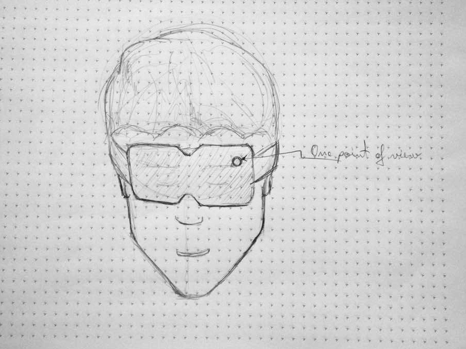
What I find that would be a solution is to make a analog-digital 2D and 3D interface to project and simulate ideas. I had visualized it as a pencil because the intuitive relationship between user and object that it already has. An analogic and digital pencil could allow you to have the ease experience of writing or drawing with a normal pencil and the benefits of software that are already developed for communicate and simulate your creations. I’ve been researching different technologies to visualize digital designs for 2 months and I finally found that augmented reality could be used to show you your 3D digital drawings. Augmented really is accessible now with a smartphone and there are good results of experimentation with it (+).
With this analog-digital pencil you would be able to understand better your ideas and show the others your projects in the real context that you are. For example, if you want to create a lamp you would be able draw it as a sketch in your own desktop in 3D with the same pencil that you are using to take notes in your classroom and visualized it with a smartphone.
The importance of this project is about using an interface that has been with humans thousands of years and including to it XXI century technology.

We could understand this object as ANALOG AND DIGITAL PEN that joins the analog world with digital world to gif a normal and intuitive experience to people.
So here we have three variables or concepts to define:
Analog
Digital
Pen
Analog:
In a technology context refers to
a continuously variable signal or a circuit or device designed to handle such signals. The opposite is "discrete" or " digital.
Digital:
In the same context is
data which is stored ortransmitted as a sequence of discrete symbols from a finite set, most commonly this means binary data represented using electronic or electromagnetic signals. The opposite is analogue.
For example if we think about few objects that got analog and digital changes in human history. We would fine two really good examples: printers and photography cameras.
Printers used to use metal molds to print a type and now with a data the computer knows that G is 01000111 in binary code. So we could make this relation of concepts:
(+)
And the same pattern we could see in analogic and digital photography cameras. An analogic camera use light to make a mold in a film and in the other side you have a digital camera that use a sensor to record the frequency of light to translate in binary code so.
(+)
As a result we could assume that referring to pen, this would be the logic:
The term "ergonomics" is derived from two Greek words: "ergon," meaning work, and "nomoi," meaning natural laws. Ergonomists study human capabilities in relationship to work demands…
In other words I have to fit analog and digital tool to work demands that could adapt to human capabilities.
By lot of years humans have been using tools to communicate, make plans and work with others. If we travel in time we can find that humans had use fingers, sticks, pulmes and pens as an interface to project ideas. And if we think about the actual work that we do these days we would find that we are involved of digital biosphere too. So, in this time the work that we do normally is demanding us digital capabilities as analog capabilities. Here we would think around digital interfaces and gadgets similar to mouse, keyboard and touchscreens.
If we go up to mouse developing and history resuts incredible how mouse turned human relationship with digital biosphere. At that time mouse just revolted the way how humans worked with computers. Nonetheless if you analyzed mouse as interface it has not natural predecessors, in this sense this is not much natural interface.
Something that I have experimented as left handed in my career took place when I had to illustrate and draw with a mouse. In school they teach me to use mouse with right hand and it was sort of easy. Nonetheless make detailed illustrations using right hand for me turns difficult and I have found an ergonomic problem because I had to adapt myself to do it rather than mouse adapts to my capabilities. And here is when I found that mouse would be different in order to have a better interface to communicate ourselves digitally.
Thinking in the best way to understand how I could make a useful tool that could bring humans the possibility to interact with physical and digital world I adopted Bit and Atoms theory as a guide because I found it as good base of knowledge to based on. At the same time I discovered 5 main questions to respond to have enough information to start fabricate the idea related to hardware, software and design:

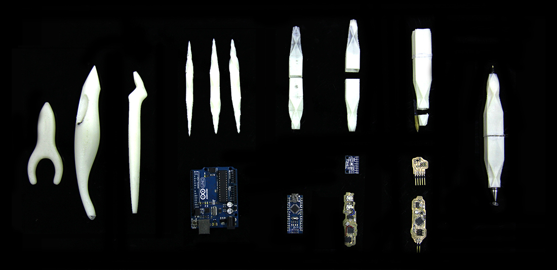
To respond this question I decided to research about some types of pens and to make this story short I had select an image to show how complex could be a pen. Then I analyzed them with the intention to identify the main components that a pen needs to have to function correctly.
Here the results:
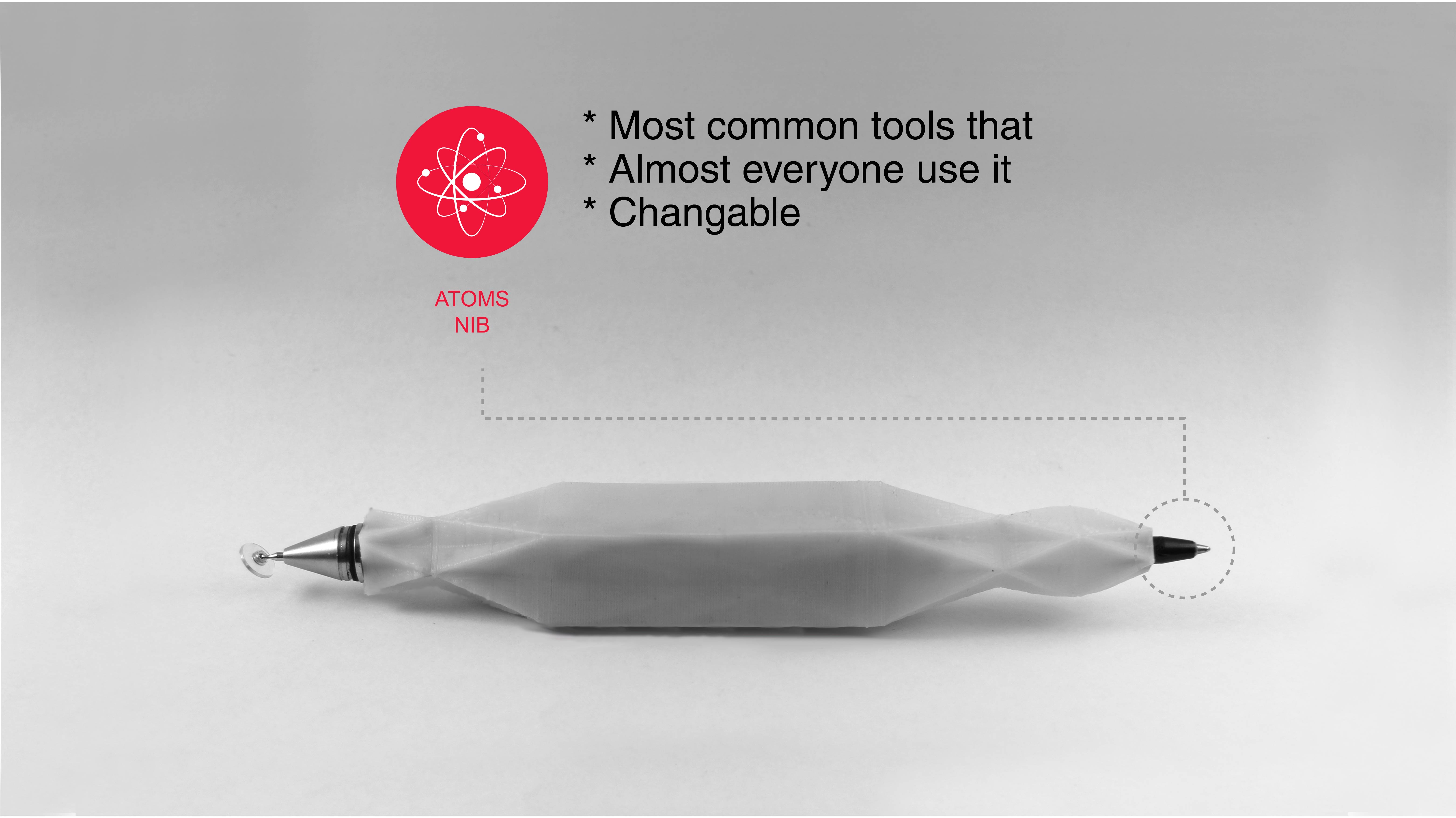
The nib.- that used to be interchangeable
Body.- that is like the structure of it
Ink Refill.- an ink container
And some mechanical parts
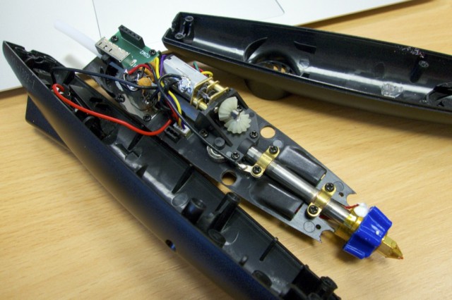
To explore and understand about gadgets that bring you the possibility to write and draw digitally I disable and search people that had disable those gadgets. Wacom devices were the first objects that I had explored.

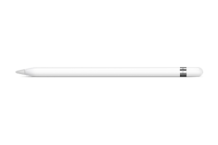
Then I research about Apple pencil that is more advance than Wacom intuos 4 technology and use the iPad features to help the user to express himself. At this point both examples need a tablet to function and to my objective were not useful.

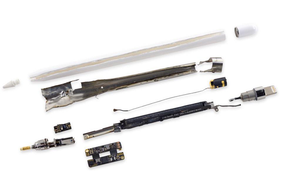
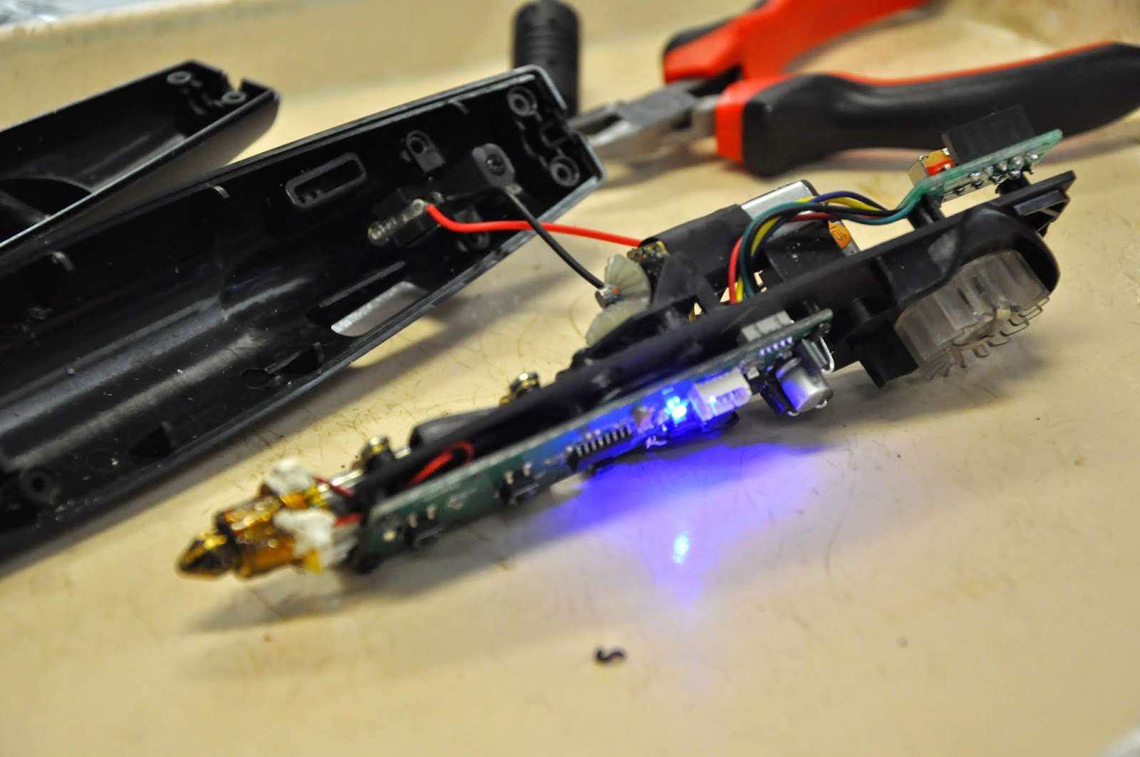
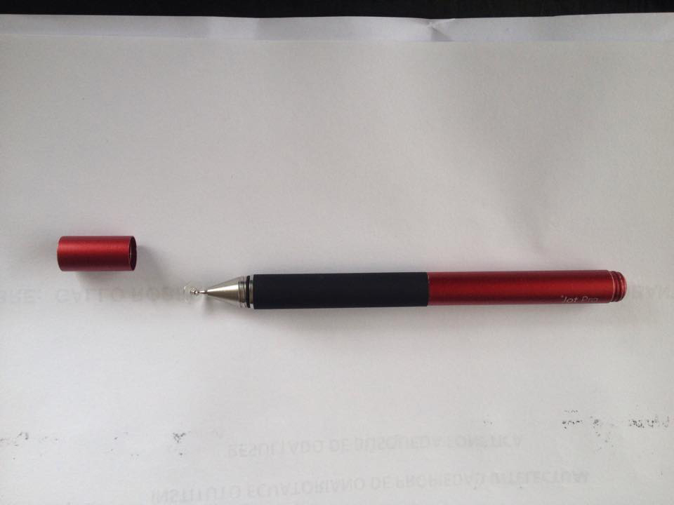
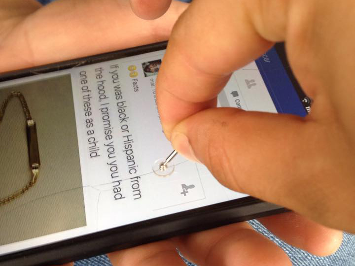
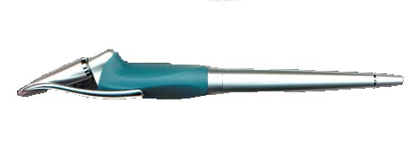
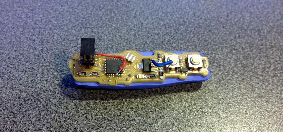
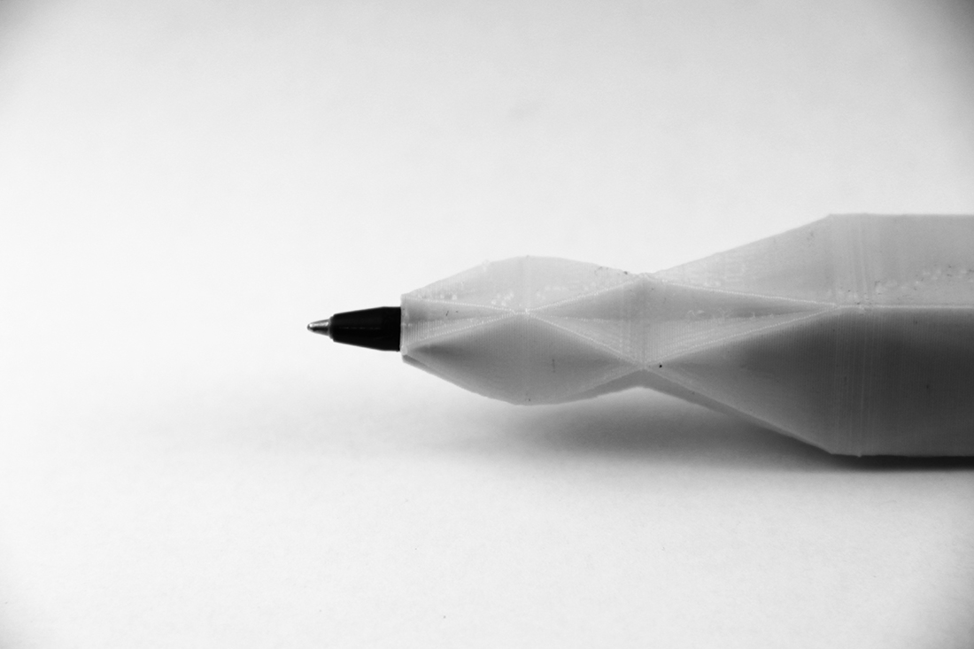
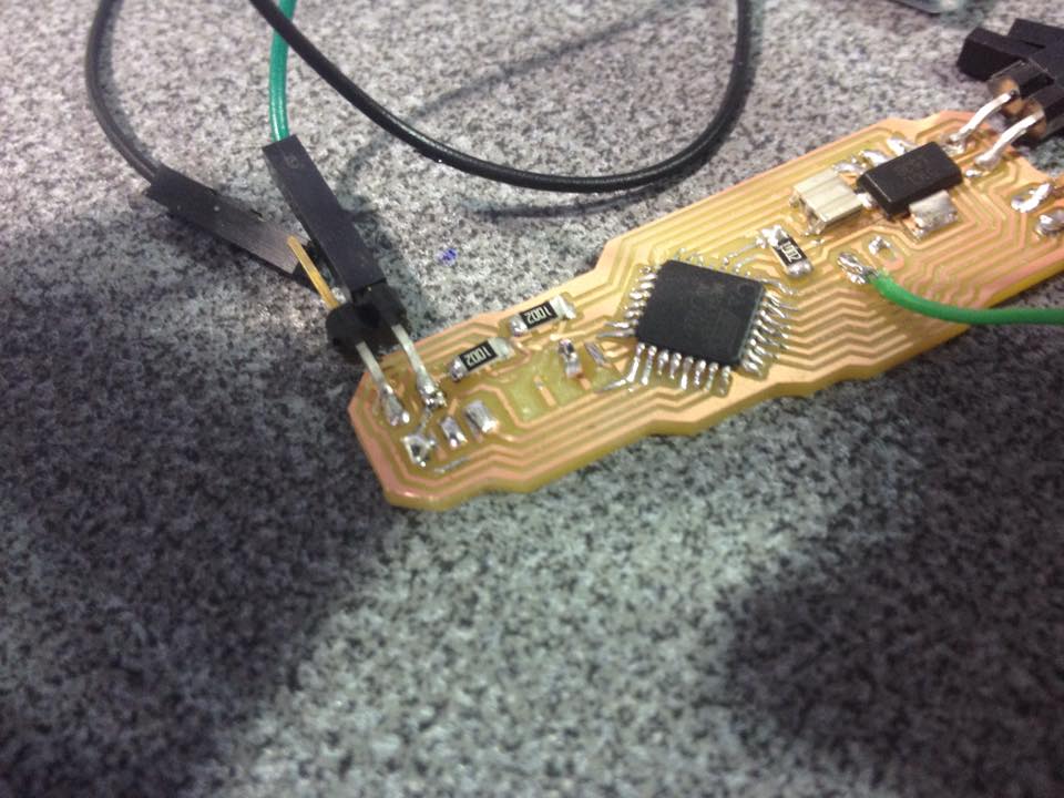
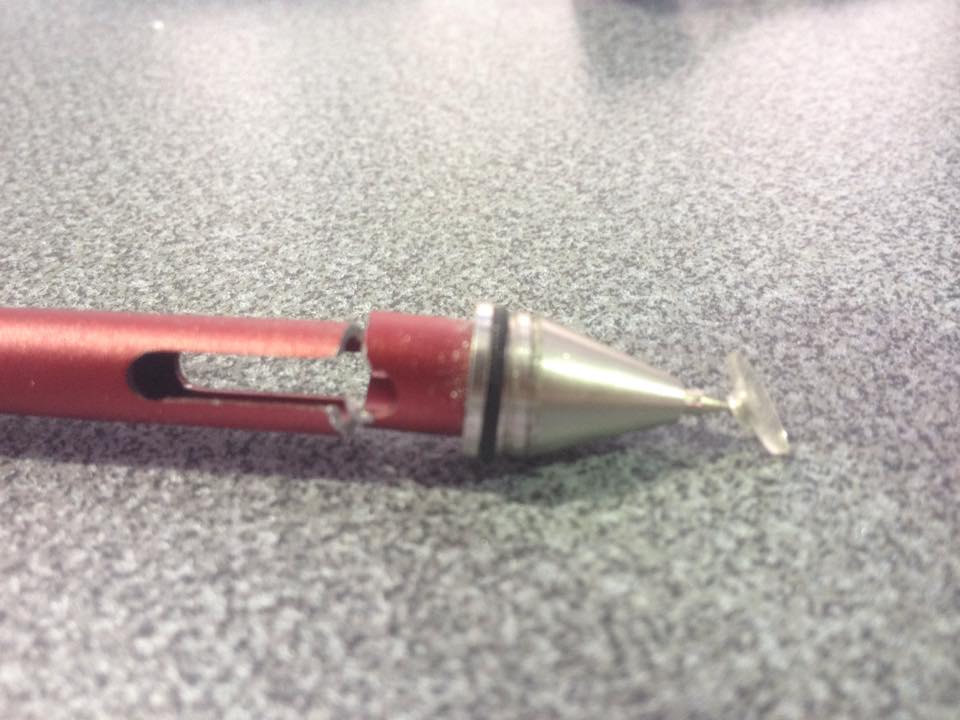
Simplicity is better. I remembered that I did buy a pen calls Jot Pen since 3 years ago to my iPad. So once I find it I dissembled in order to recognize how it works. What I get of this experience was surprising; the component that gives it the possibility to draw was just the point of the nib as you can see in the third photography. I did not see it before the phones screen is a capacitive sensor that functions by the earth contact that body produce when you touch it.
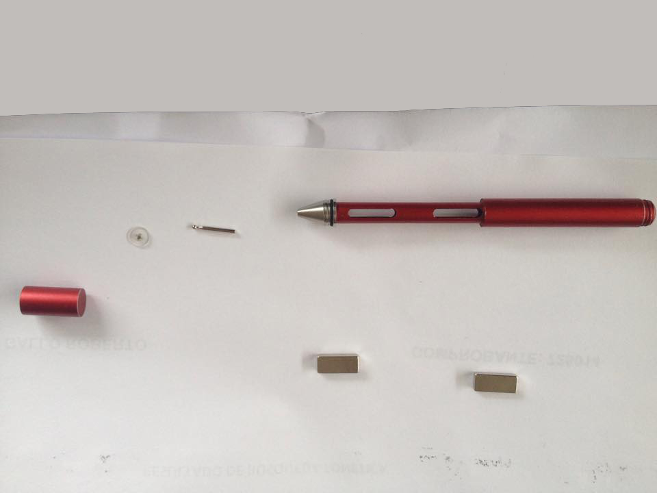
Here the results:
The nib.- that used to be interchangeable
Body.- that is like the structure of it
Microprocessor and in-circuit board.- allows you to digitalize movements.
Energy supply
And some mechanical parts
At this point I had responded first 2 questions about analog and digital pens and I continued with the others.
Here I did understand that an important thing; If I write something with the pens that I have analyzed I have to use a software that would give me 2 options: make raster traces or vector traces but no 3D traces. So, the logic tells me that I have to add something to provides information that I could transform my movements in spatial traces.
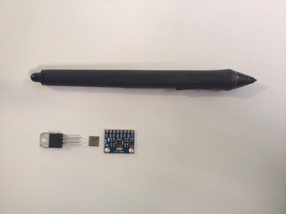
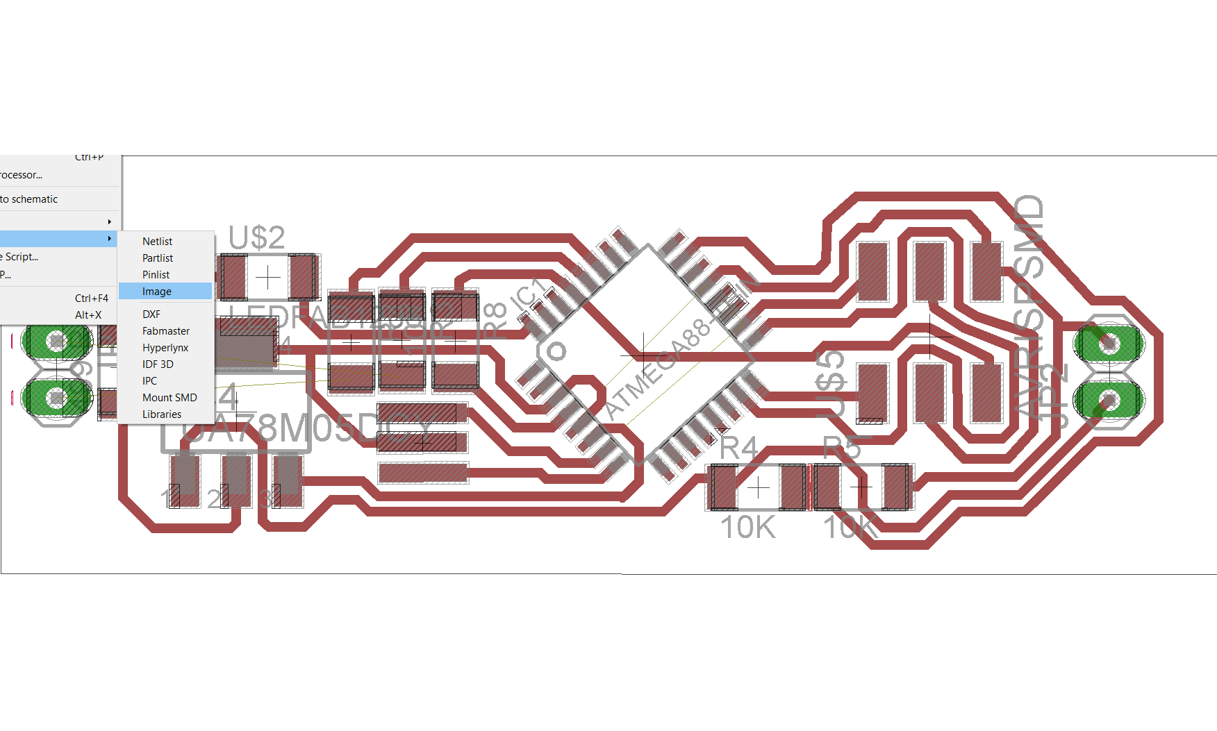
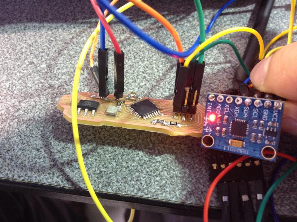
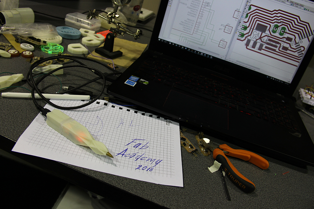
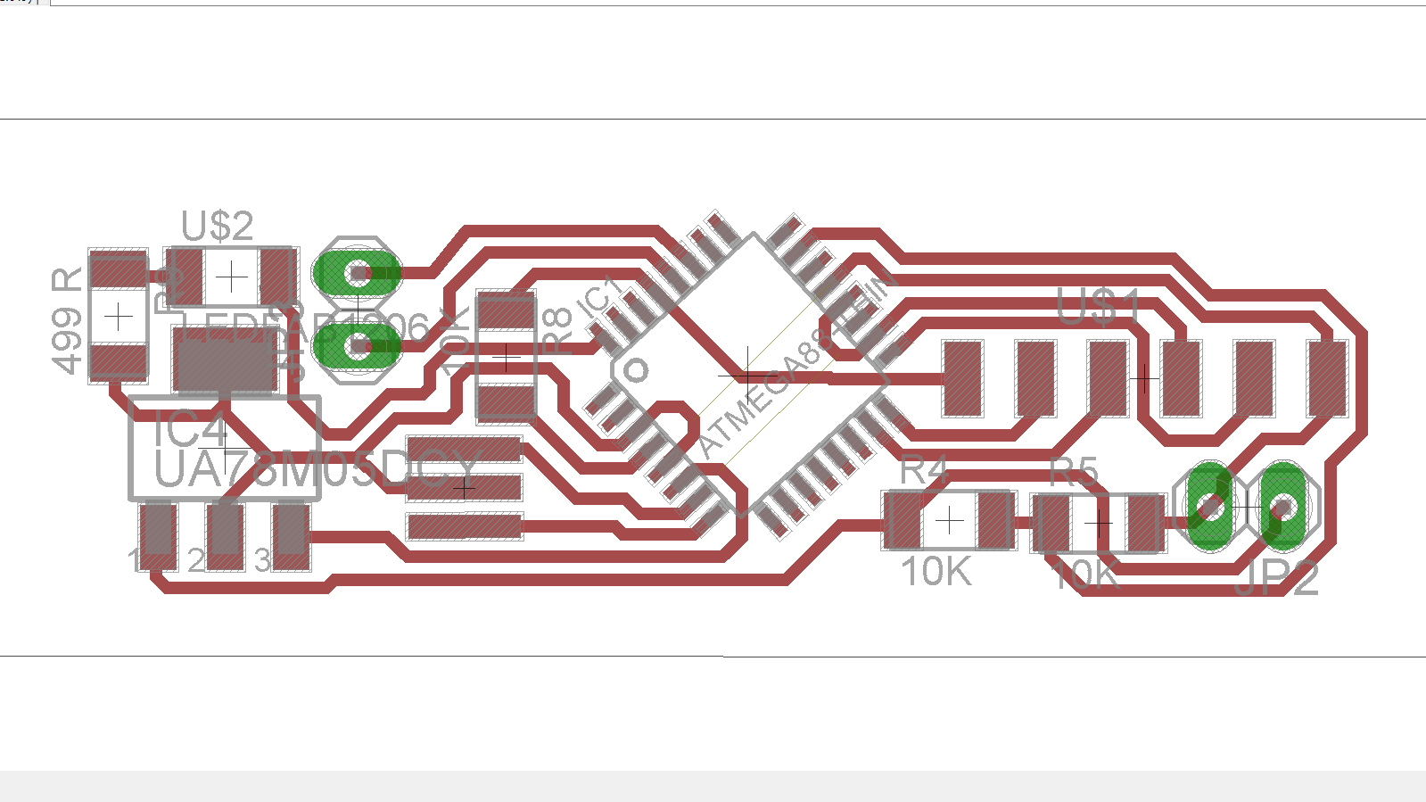
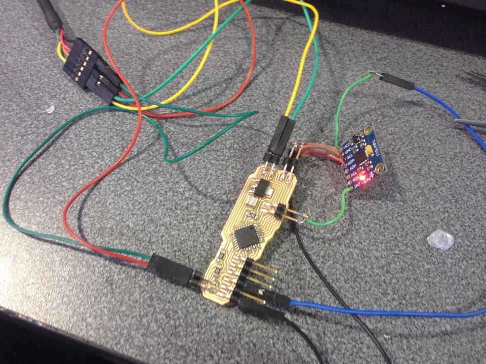
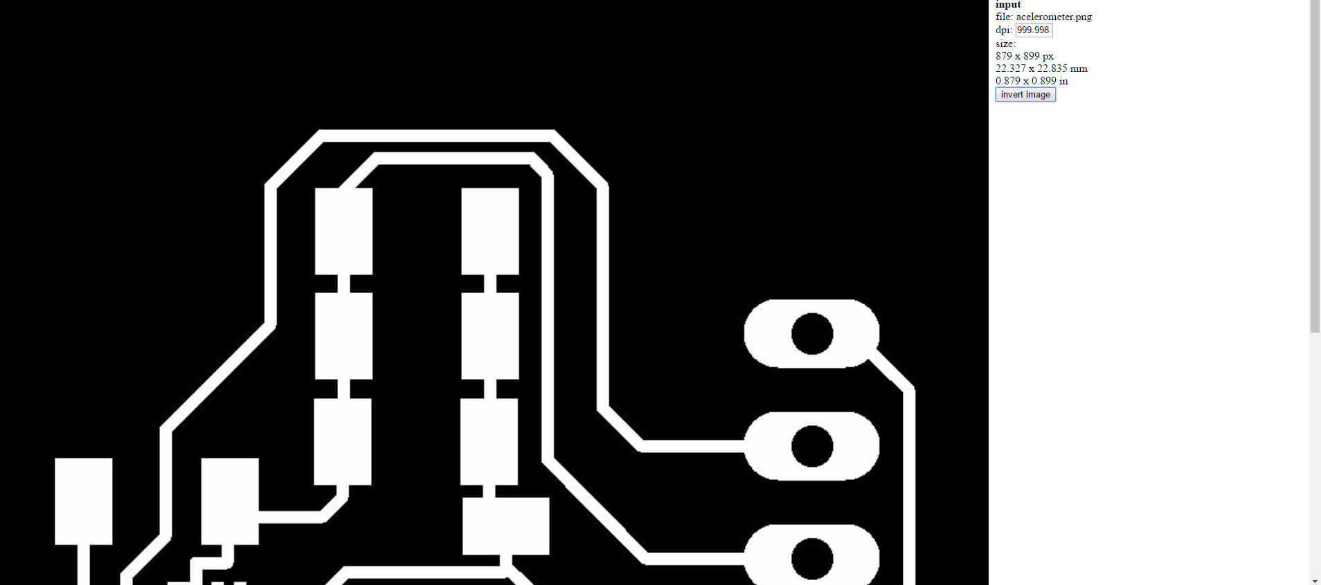
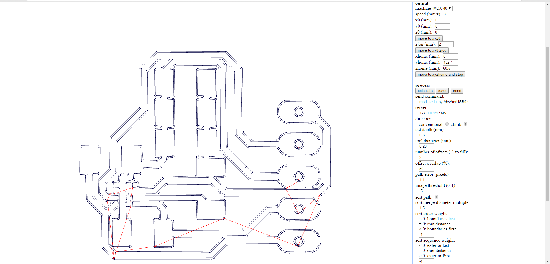
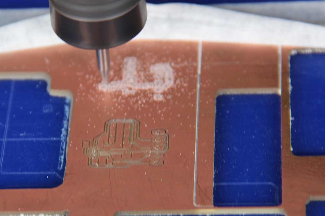
After looking some sensors and mechanisms to do what now I understand as 3D tracking I catch that an accelerometer could help me. So, I started disable some things like cellphones, other gadgets and an MPU-6050 Arduino module. At this point we already pass the in-circuit board Fab Academy class so I design the board to my final project. Then I got an eagle library to de MPU – 6050 accelerometer component that I did include to my final project board but I caught a problem, the fab modules did not recognize the pin traces to mechanize it. After some months I found that the problem origin was the resolution of the image that eagle was given me, I was trying with 500 ppi and you could increment that resolution without affecting the image size.


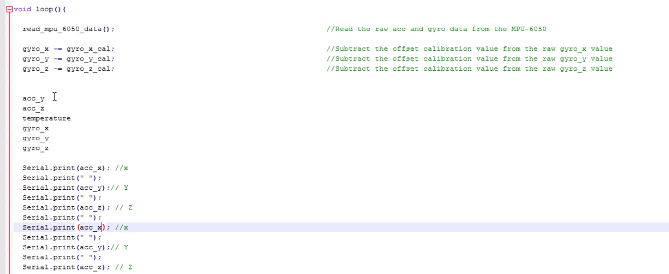
I decided to install an accelerometer in the pen to generate data. At the beginning of my exploration wanted to find a way to make a cellphone application to receive accelerometer data, process it and get an augmented reality draw. So I did a tutorial of MIT App Inventor 2 in order to understand how receive data by Bluetooth but when I tried to process that data in order to get position I realize that it was not as easy as I had imagined.

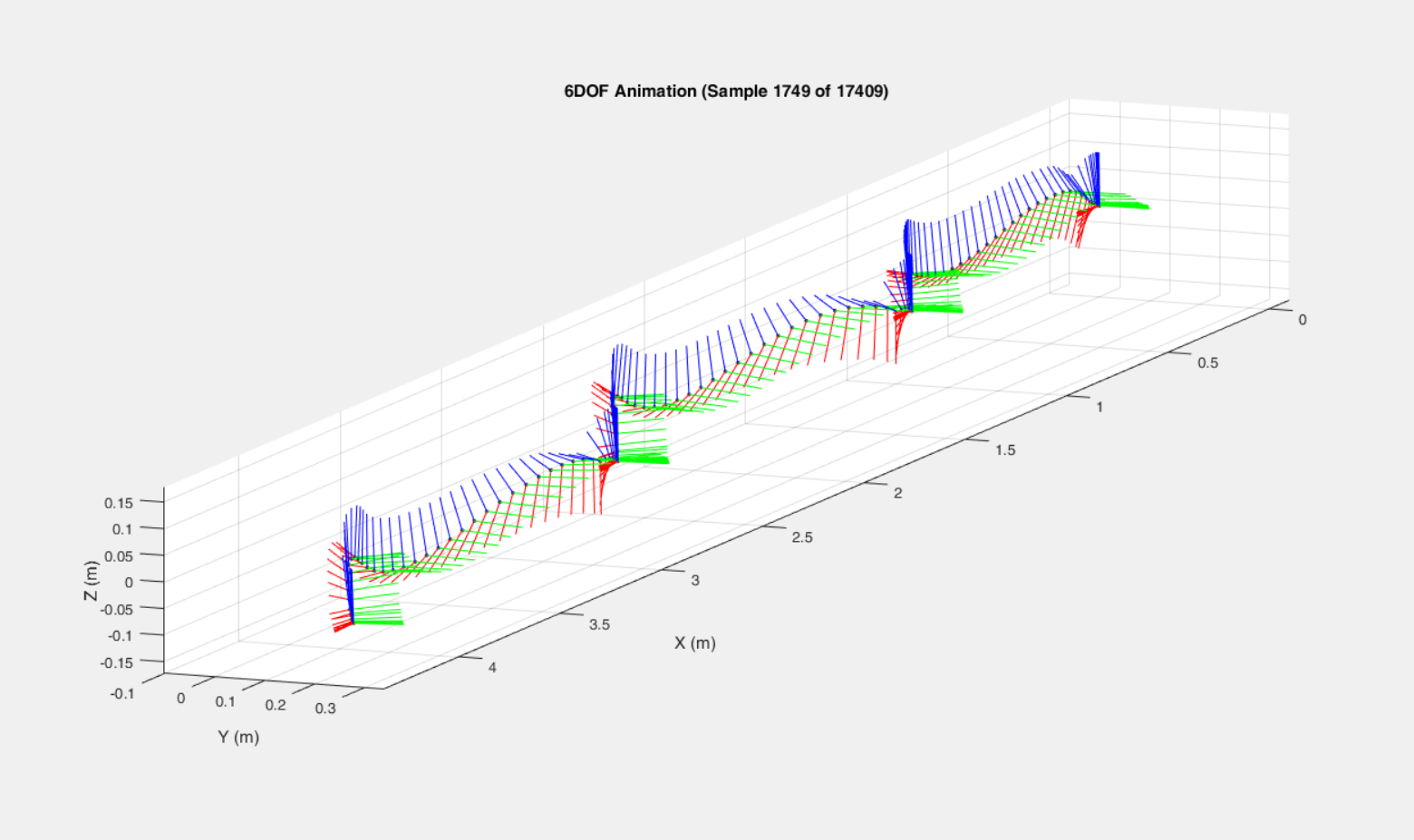
After looking lots of options to make a vector with accelerometer data I had realized that I was researching “how to make 3D tracking with an accelerometer” and the system is called IMU (Inertial Measurement Unit) that use accelerometer, gyroscope and magnetometer data and is used for lots applications as inertial navigation system. In this context I had to discover a method to transform that data to a spatial vector. And at this point I finally achieve my goal obtaining Sebastian O.H. Madgwick, Ravi Vaidyanathan and Andrew J.L. Harrison 3D tracking develop. Please see the video.
I’m asking this question is because my design methodology. Every idea that I develop must be proved by me some months of years. According with my methodology this pen would be proved (in this case) in a Fab Lab because digital fabrication is what I’m doing normally. So I decided to change a little bit my initial idea about drawing in virtual reality software for the reason that Sebastian’s develop that I’m based on already draws virtually a vector and what you used to do in Fab Labs is input data and output it. For this reason I had decided to research the possibility to transform my accelerometer into position and then in G-code maximizing my output data possibilities because Gcode is a standard.
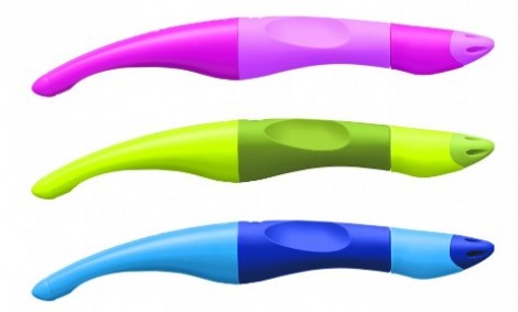
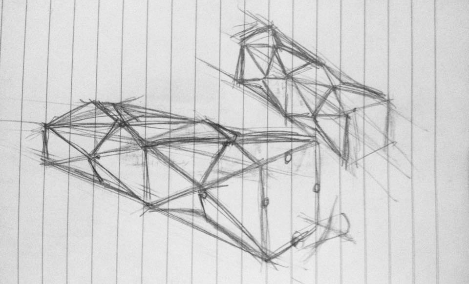
One of the main concepts that are part of product design is the relationship between object and user. So it’s important to mention and emphasize an ergonomic shape to this product. And here is when design makes sense in product developing. To get this goal I have research some ergonomic pens that would help to sculpt a friendly form to this intuitive tool.The result of the ergonomic pen research gave me three models showed below this paragraph.
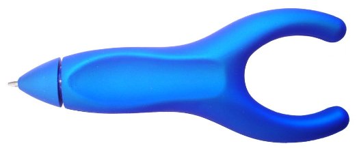
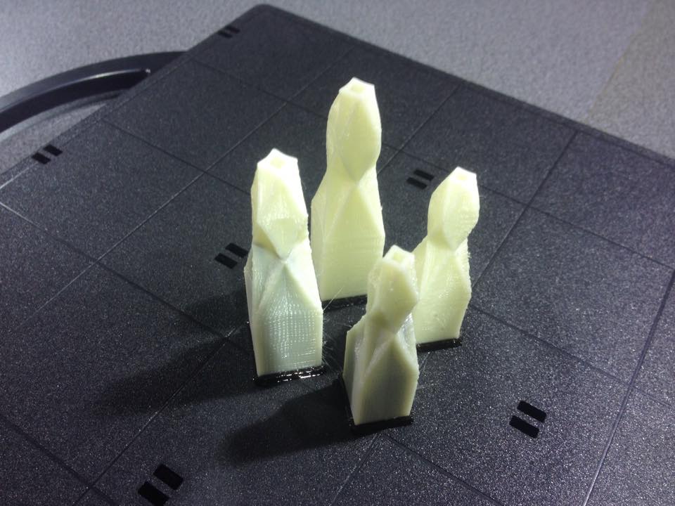
To analyze each shape I have decided to 3D model them in an aided design program making rapid prototypes. Then I did 3D print the models and ask some people to taste them in order to get information and figure out how my 3D model needs to be to give a friendly experience to it user.
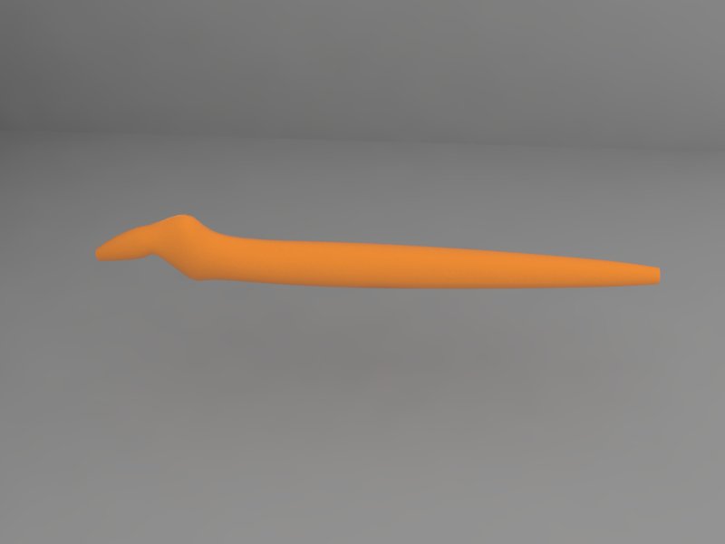
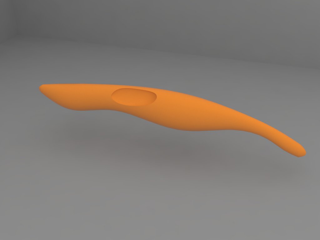

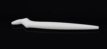
Here the model replications printed in 3D with a Stratasys Dimension 1200s

The criteria that I use to measure which pen were better to draw in 2D and 3D is in the next image:

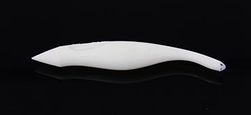
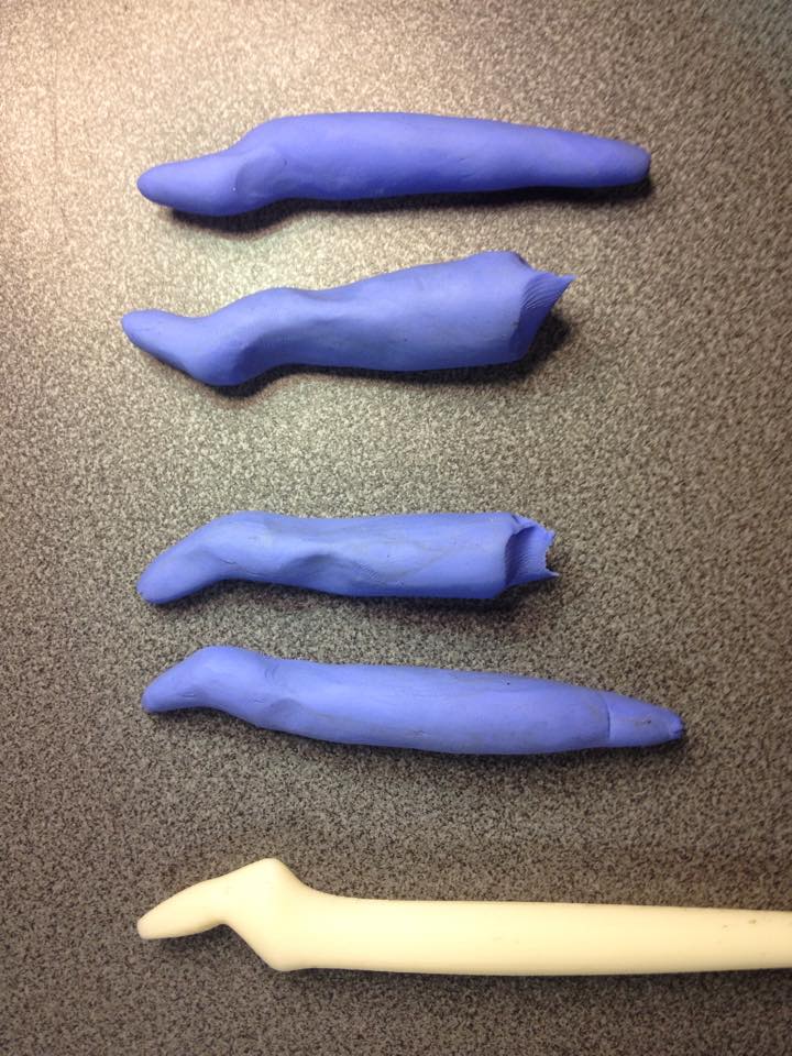
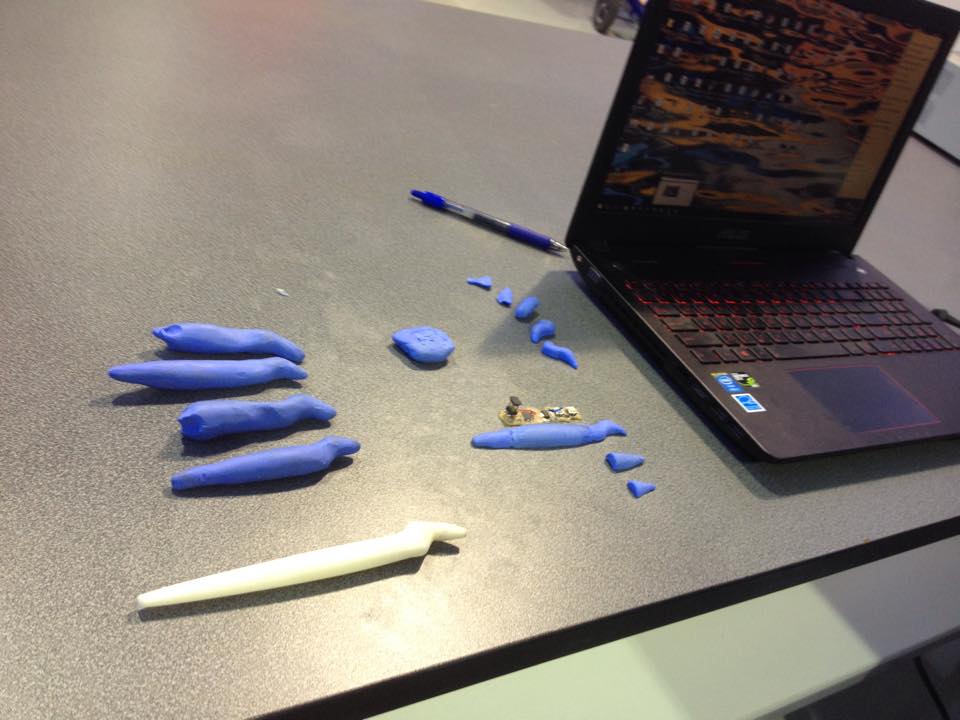
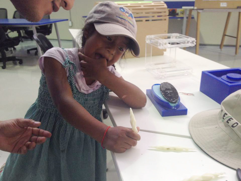
I tested this ergonomic pens with 20 persons form Yachay city and Quito city including left handed, right handed, males and females in order to treasure the best design for them. Once I got the results I discovered that the normal pen is important because the habit that people already have and that Yoro pen (first image) is the best to draw in 3D. At this point I decide to make 4 clay reproductions of Yoro pen and ask 4 people to grip clay to have a tridimensional base to work in my analog and digital pen design.
Hearing, observe and then propose. My philosophy is simple observe your environment carefully and once you are sure that you have enough information propose as solution or innovation. To write you must learn to read, to make music you must learn to listen, to manage your projects you must understand how other manage their projects. And hear Neil's first class teach me something that I was trying to understand about project management…

So I decided to divide my final project in spiral loops.
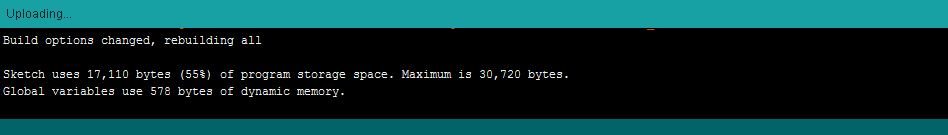
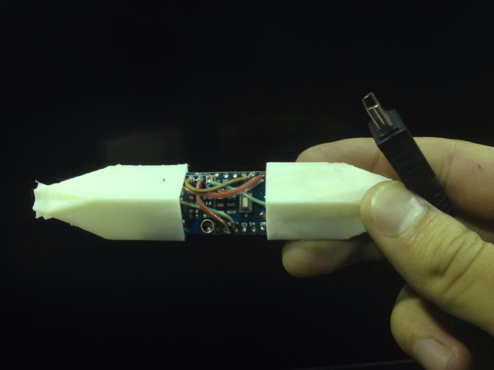
I started developing electronics, programming and design by speared as modules thinking to join them in the future. One main difficulty to achieve this idea was encapsulating everything together. To the first loop I tried to make a simple in-circuit board work, prove the algorithm to transform acceleration to G-code running it in a CNC simulator and design the main pens shape.

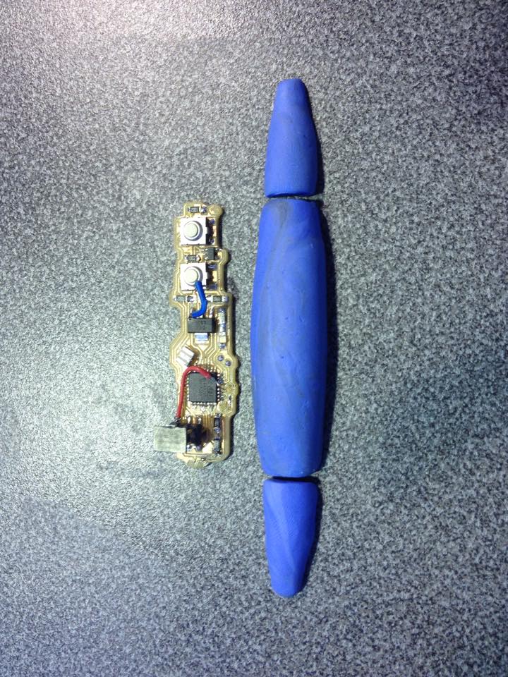
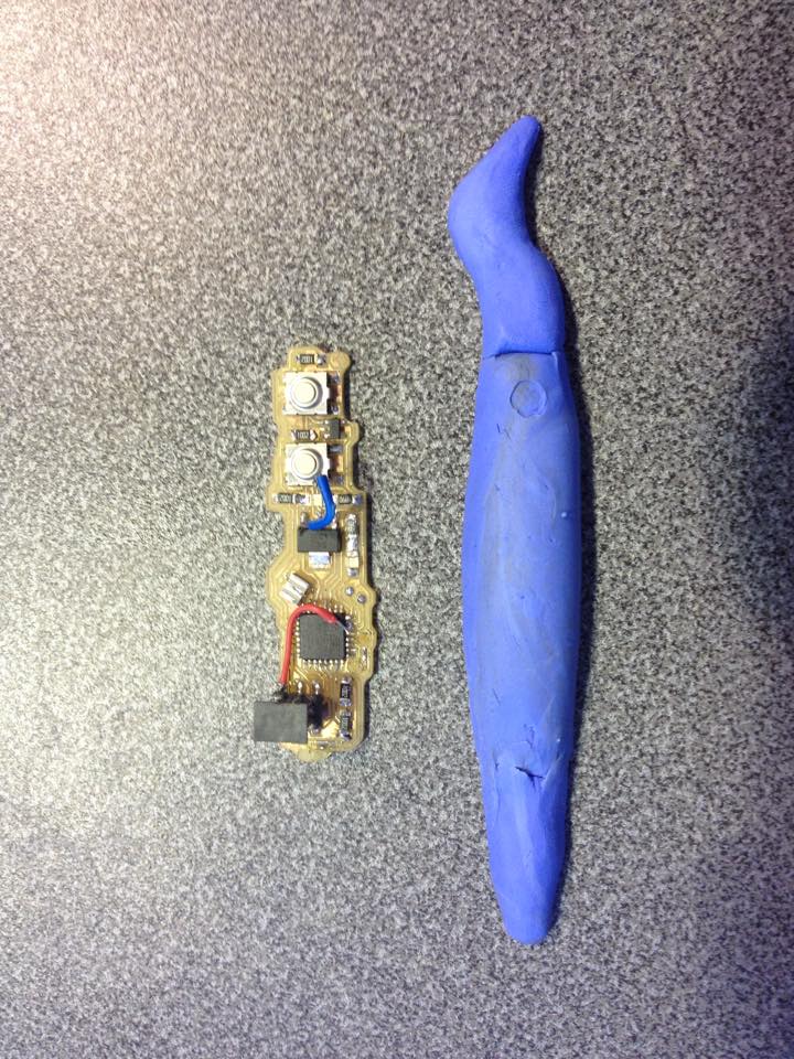
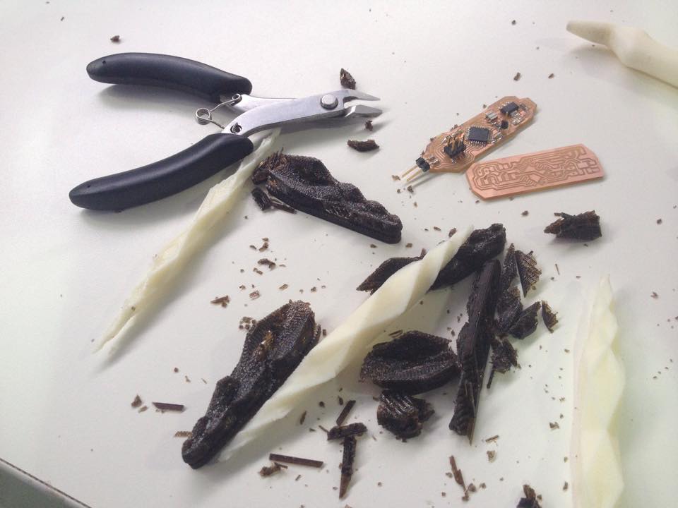
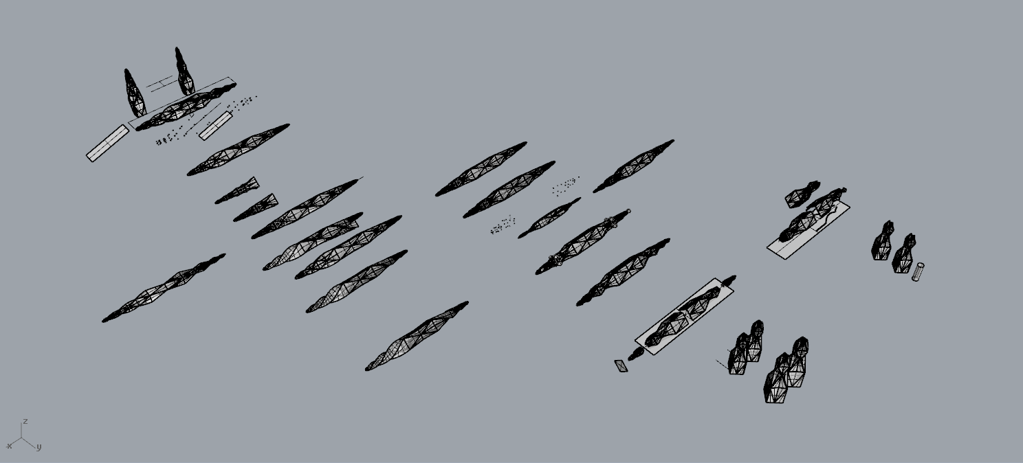
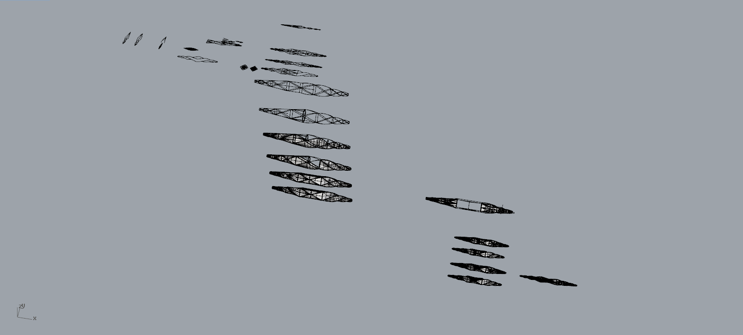
As you can see in images I had been comparing the volume of in-circuit board and the pen that people select as the better to draw in 2D and 3D.
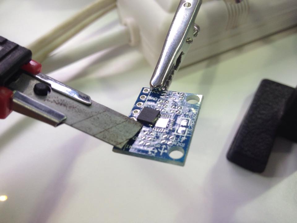
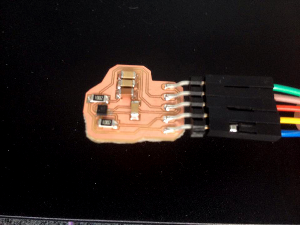
Once I found an option to solve the volume problem I tried to put that in-circuit board to work but I found that it was not running because the board had some design problems. I tasted it soldering to cables but it was just wrong. So I started again with in-circuit board design.
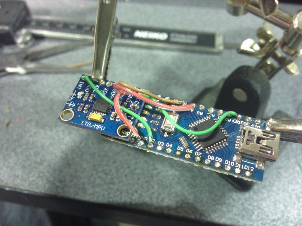
In the other hand, I tested embedded programing with Arduino Nano and it was working correctly.

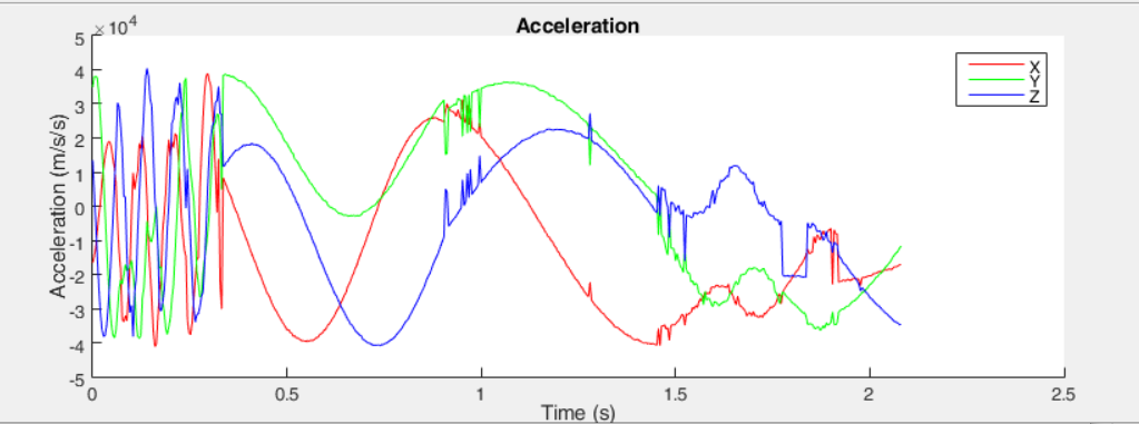
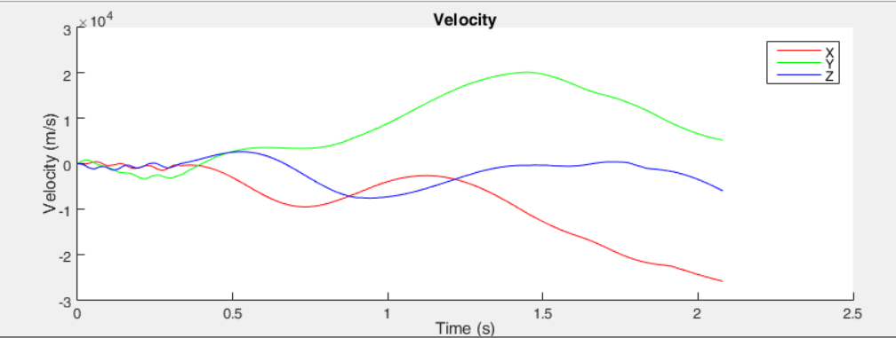
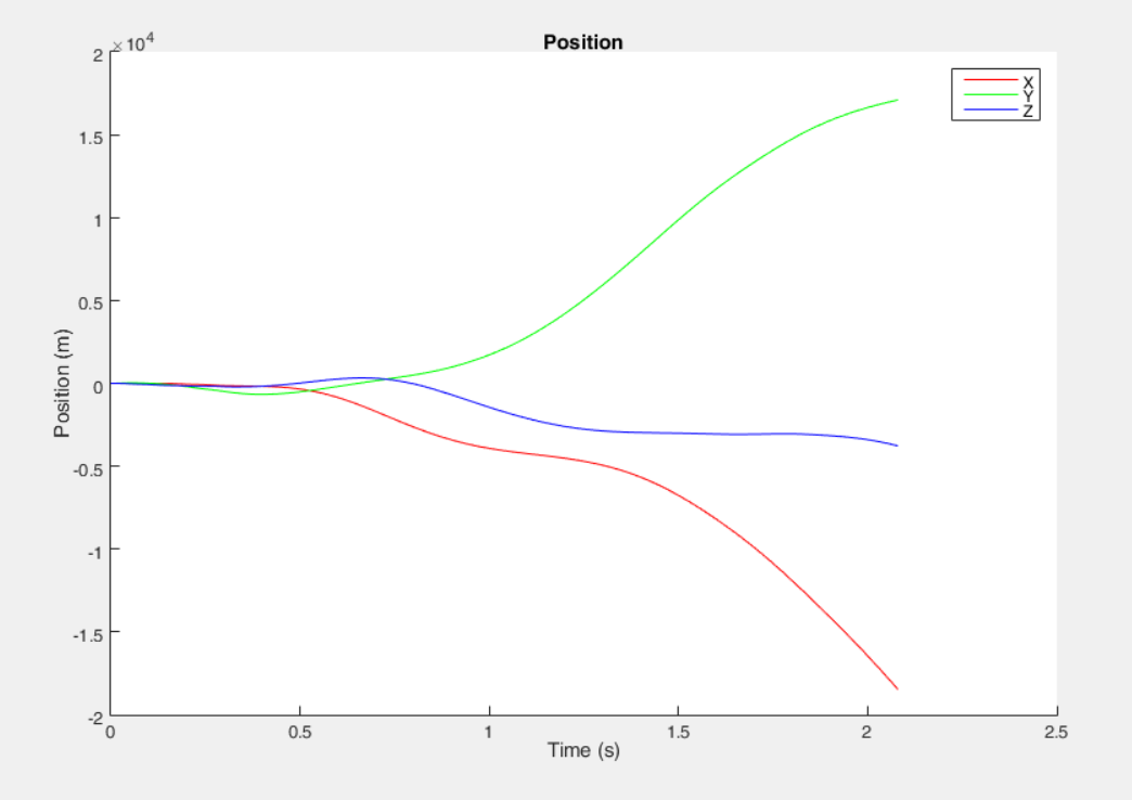
Then I prove the program to transform the accelerometer data into position and I had some problems understanding Mathlab because I had no experience with it interface. And here is then I receive help form Juan David Valenciano a Colombian guy whom I meet in Yachay. David had the practical experience to guide me to my objective. At this point, he helped me to find the file that MathLab program was giving me detailed in next images.

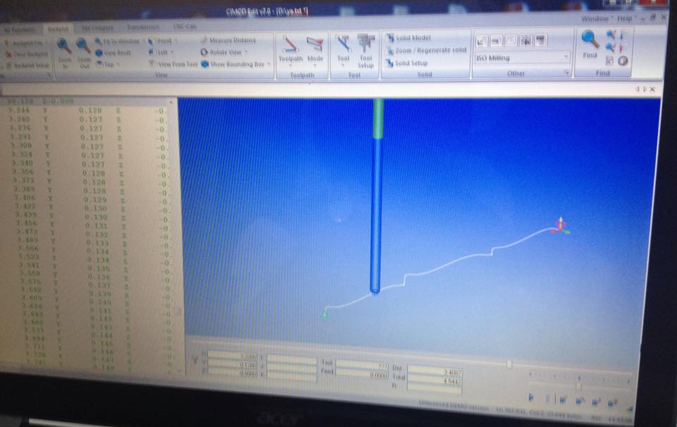
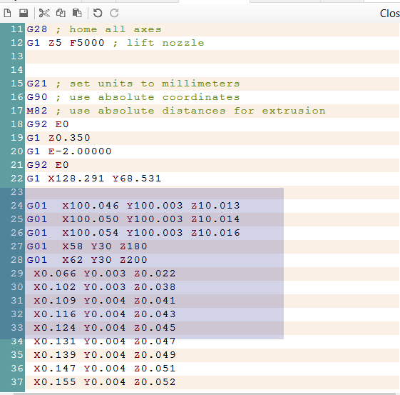
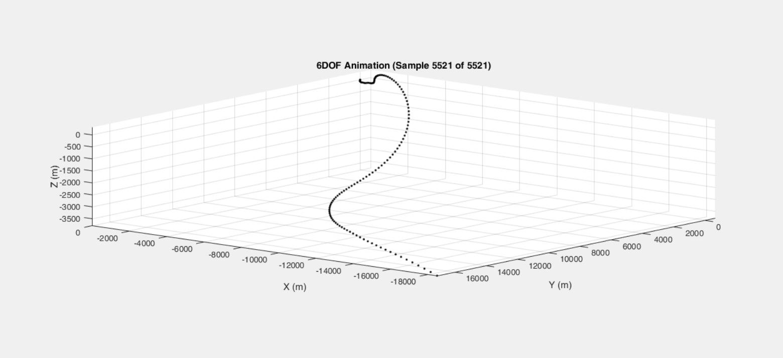
At this moment the project turns real. When I took the data that Sebastian HO made to his project, run it in Mathlab program and adapt it manually in order to have my first G-code data test. And was just incredible how well the idea worked.
You may see the same draw in the previews image and the image after this paragraph. I use CIMCO software to test my G-coda as you can observe in the video too.
With the embedded programing and G-code test running the software module to the first loop was completed and I continued with hardware and design part.

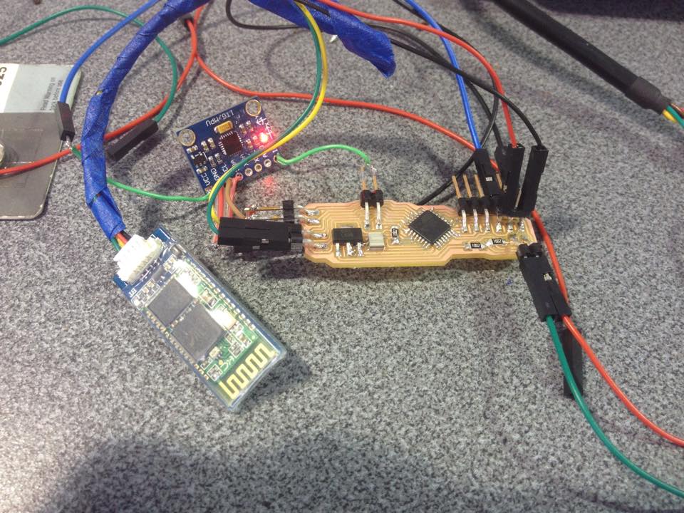
Then I had design another in-circuit board main module that had not accelerometer and Bluetooth integrated. Having more luck than the last time the Atmega 328 allows me to burn bootloader but I could not communicate MPU-6050 with it so my main board did not gave me data. Step by Step I had to be patient.

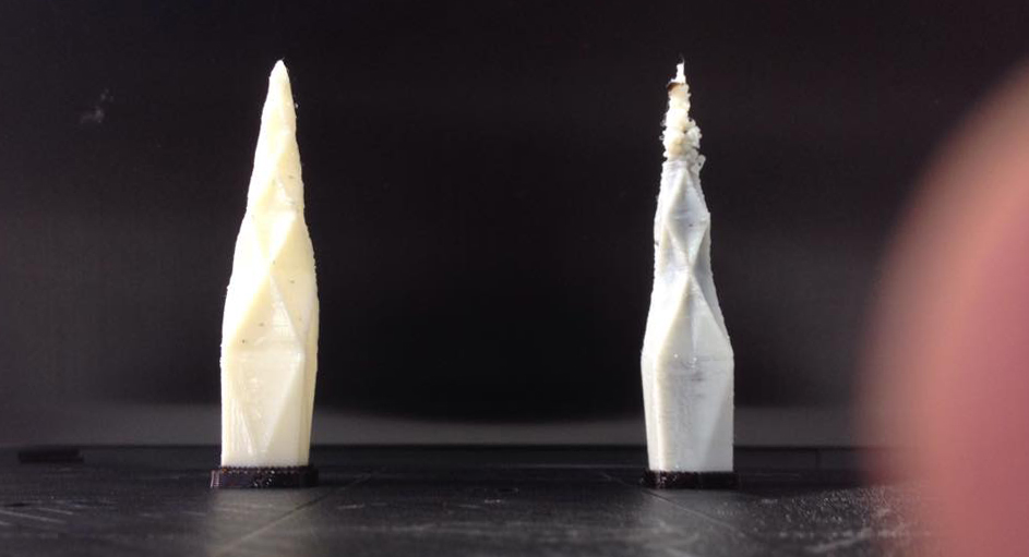
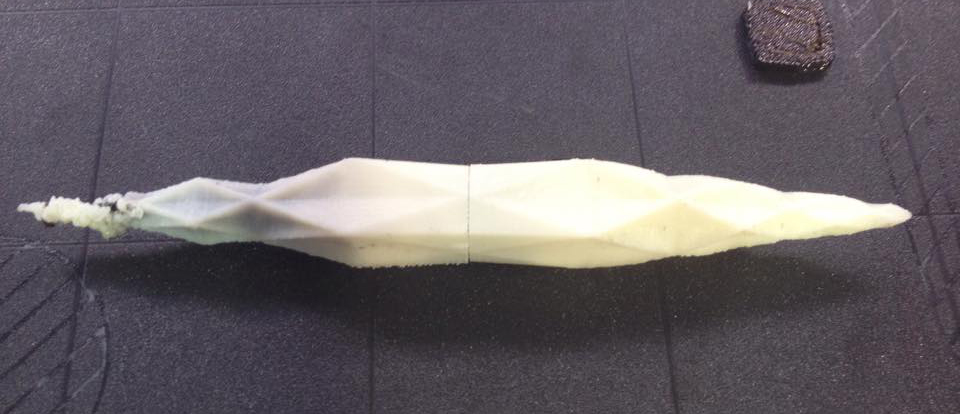
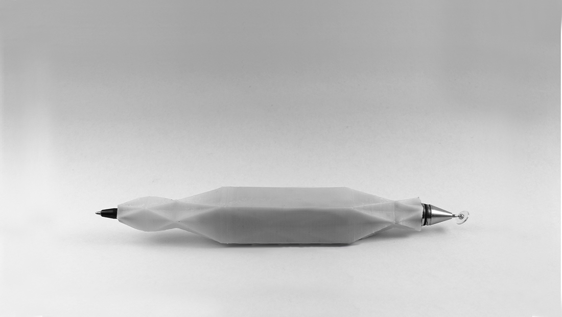
Continuing with design, I discovered a natural pattern to apply to my design that is called Pi number. Playing with Pi number and with a atoms as organic shape and a bits as a geometric shape logic I got 2 sides of the pen. The first side dedicated to atomic word and the other to digital world.


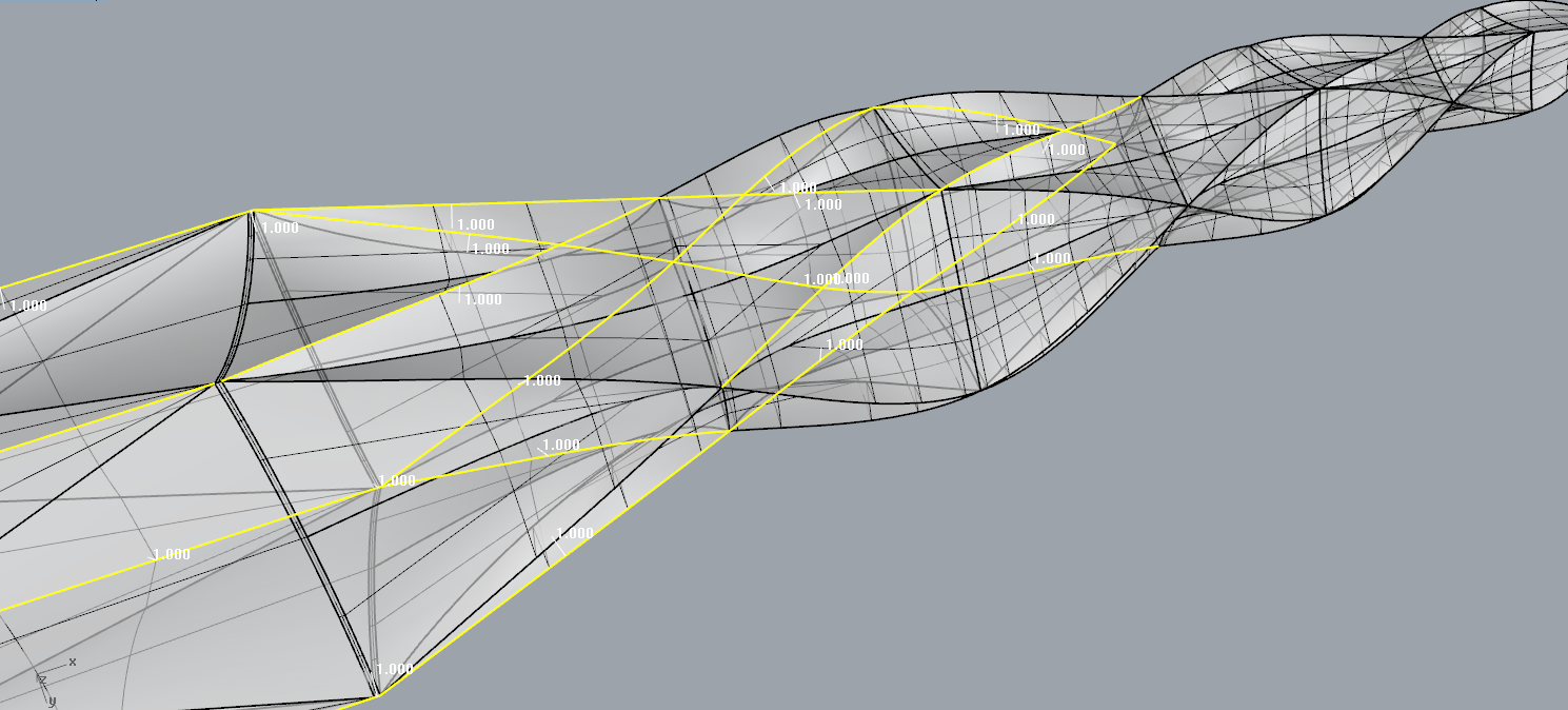
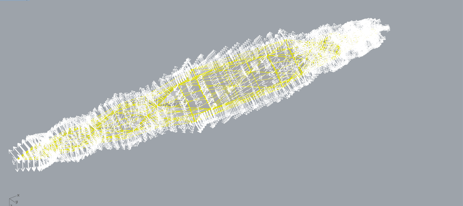
I have to mention that I realize that in all the prints that I did about Bits and Atoms pen the atomic part of it did not needed supports rather than digital part of it that has string lines. I thing this would be a good topic to make a research about morphology of them.


At this point the first phase of develop was completed. The systems were working spared but working. The main problem was the in-circuit board that was not giving data to the computer.
In the second phase of develop I started researching more about G-code in order to receive and generate data with correct G-code nomenclature because the last G-code test worked well but I did not understand exactly how it runs.
At this point I was trying to test in the data position in other program to control another machine. Repetier is the program that we used to control the 3D Bioprinter that we did in Machine Assignment so I was proving with it. At the beginning running a normal file because I was cheking out the logic that Repetier does.
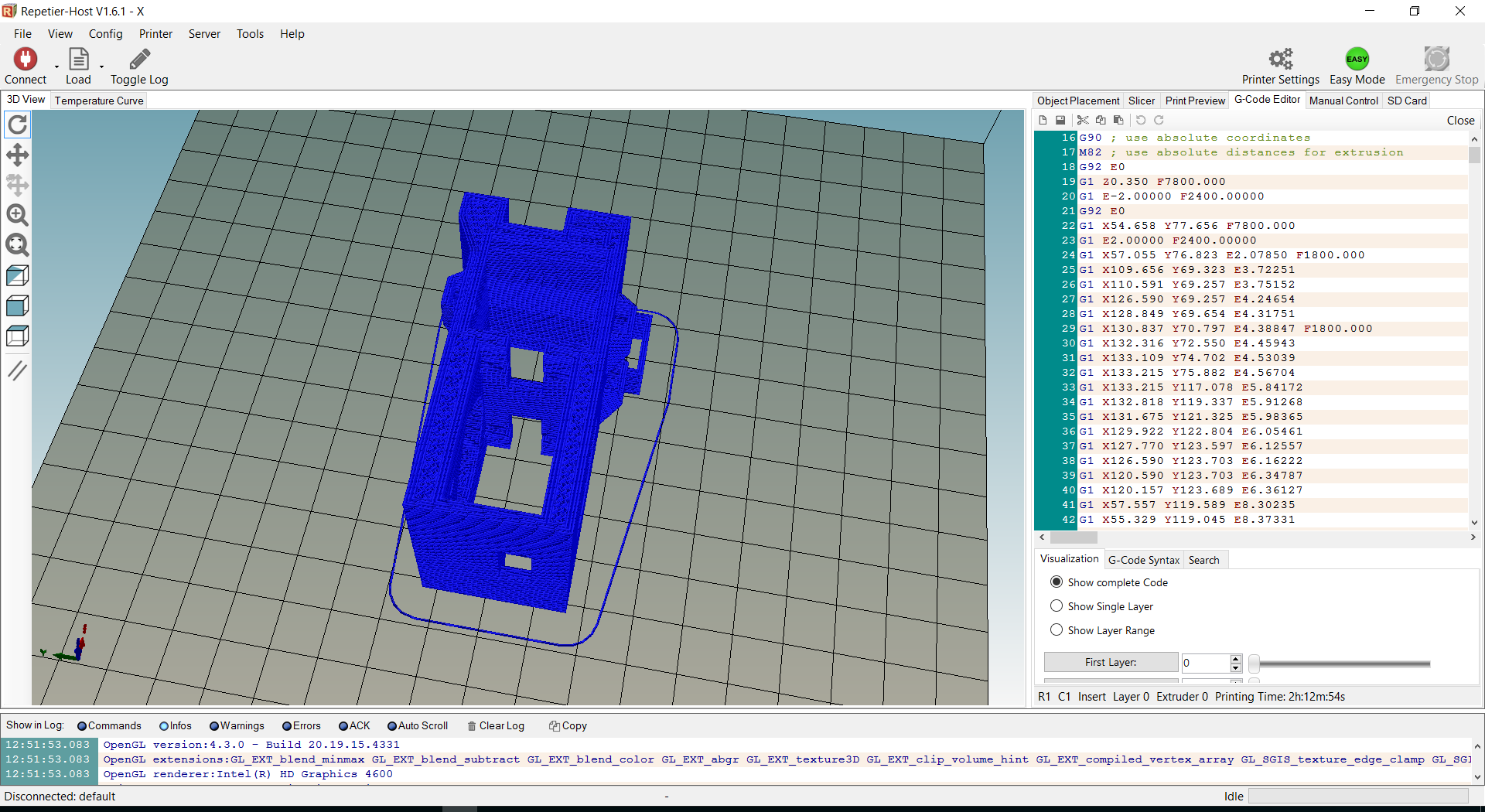
When I thought that I had understand the logic about G-code in Repetier I test with position data that Mathlab was giving me and I didn’t worked.

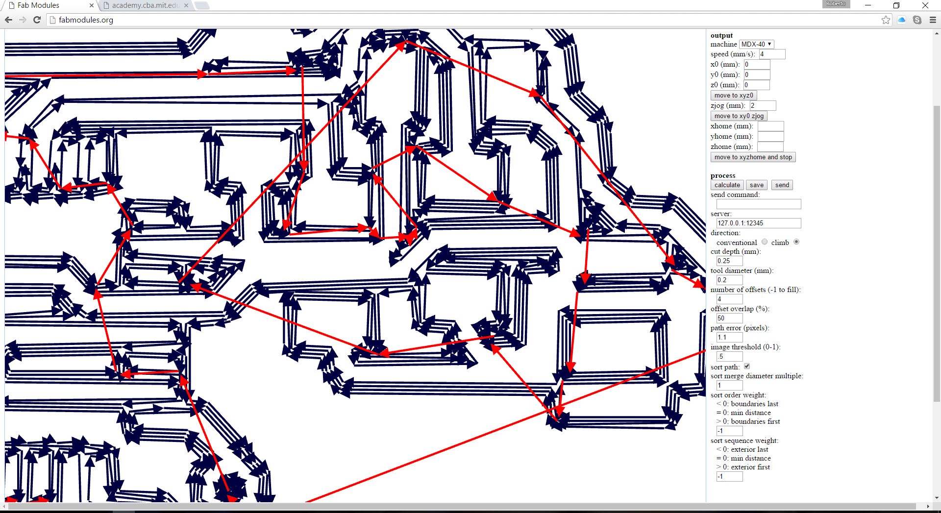
Here I realize that is more complex to control a 3D printer than a CNC machine because the extruder it has more code to control extruder and temperature. I decided to download trail version for CNC Simulator program to taste the G-code that I had make manually. Here I learned that CIMCO gives you more liberty to generate G-code rather than CNC Simulator. In CNC simulator you have to use correctly G-Code nomenclature. And that help me to make a better G-code to run in Repetier.
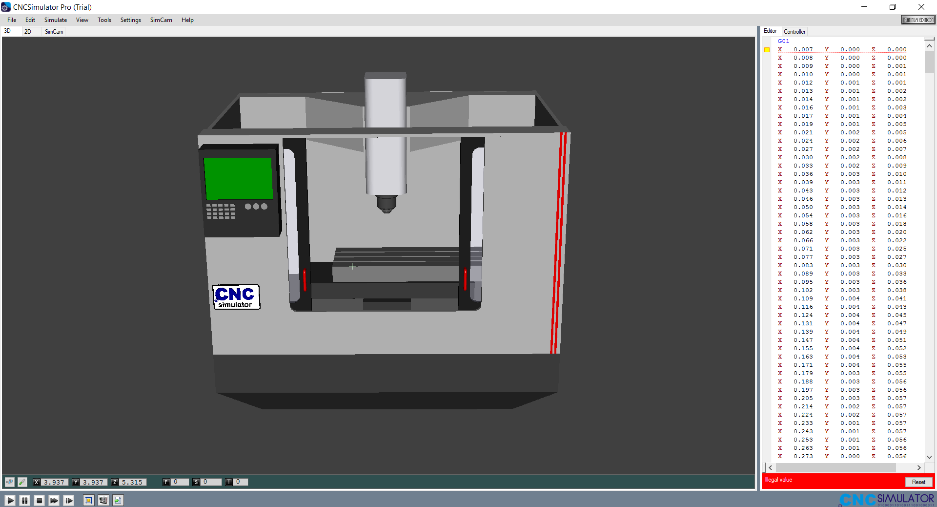
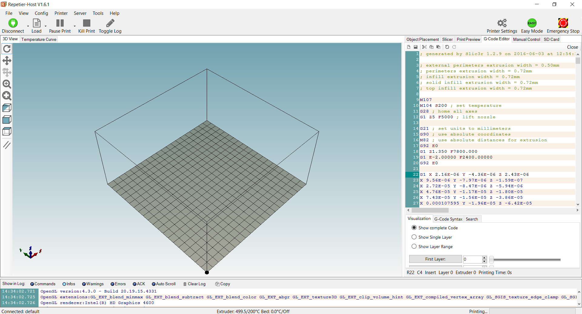
At the beginning of the test it did not recognize my G-Code.
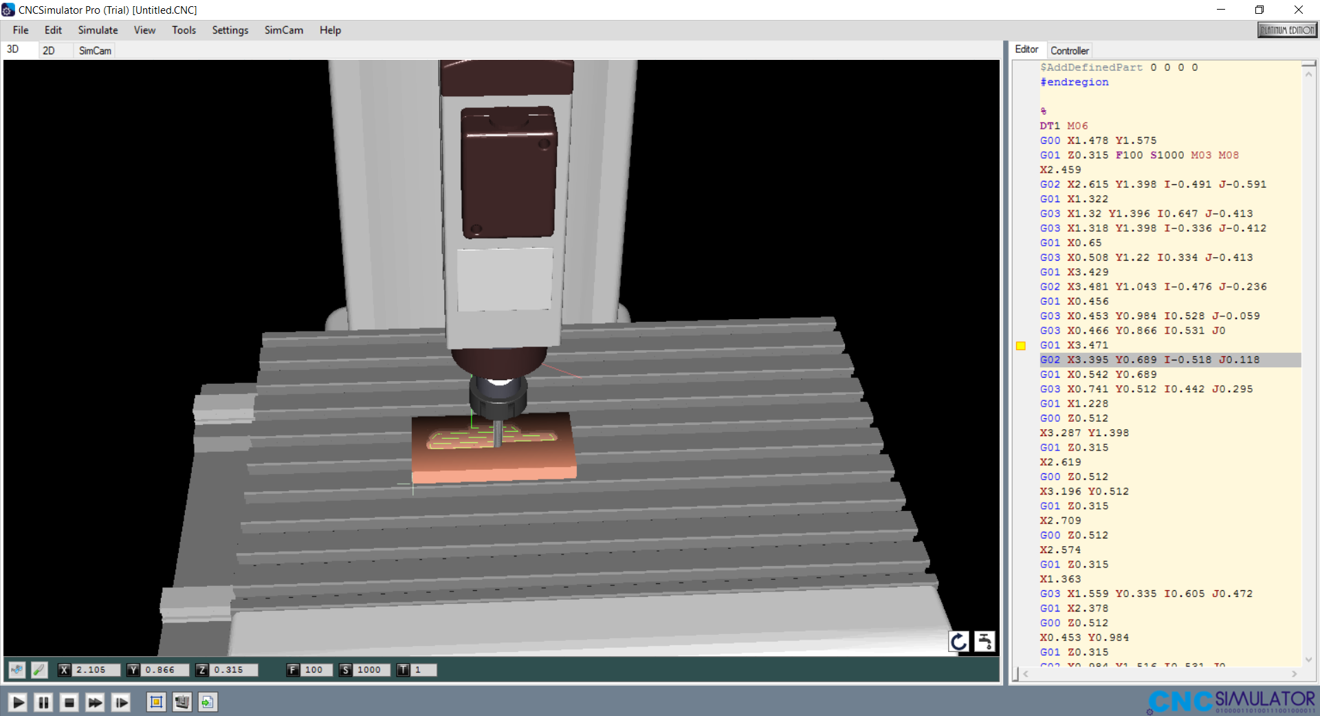
So I run an existing file and copy the introduction and the end of that code.
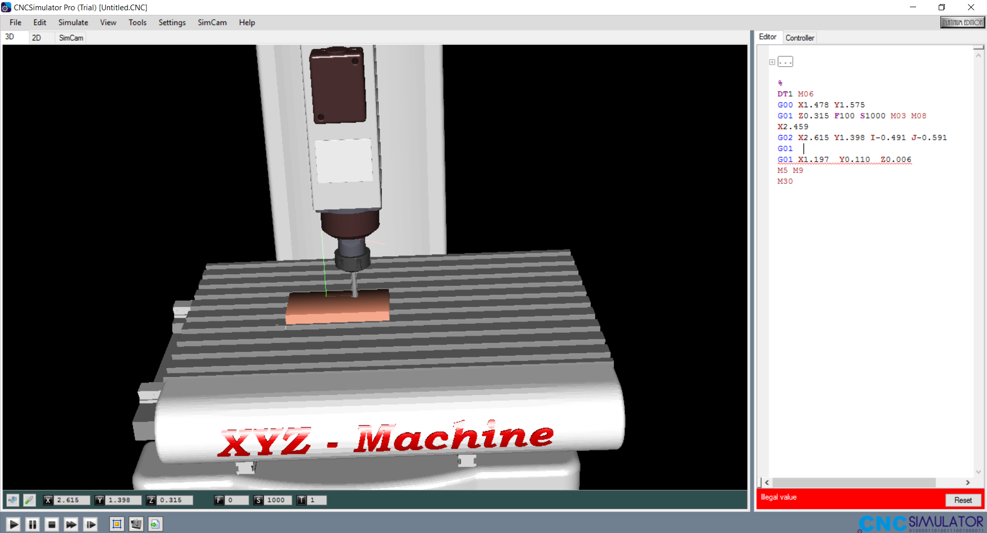
And finally I run my G-code as you can observe in the video.

Then Juan David modified Sebastian’s Mathlab code in order to read a .CSV file with MPU-6050 data. At this point the input and vector process were joined but not proved.
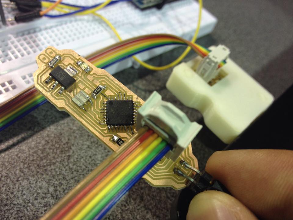
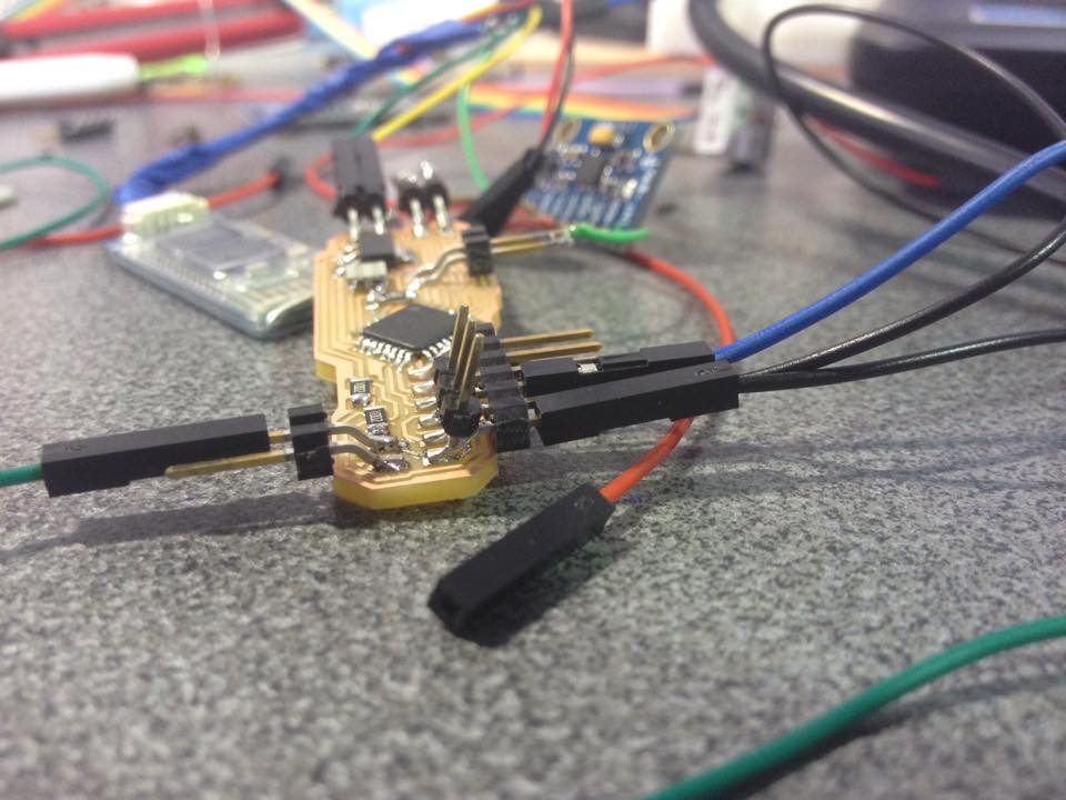
Once again I retook the design and hardware modules with the idea to join them. As you can see in the photography below I have use the board that was not giving me data to plan again how to put everything together.

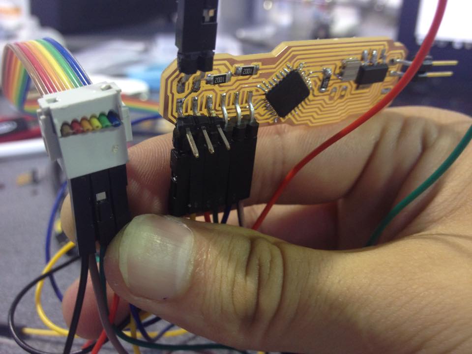
In order to optimize my main in-circuit board size I decided to try to change the serial port ISP to a SPDI port because it was less fat than ISP but I conserve the same pines to load my program in Atmega 328. Look the change in the next 3 images.
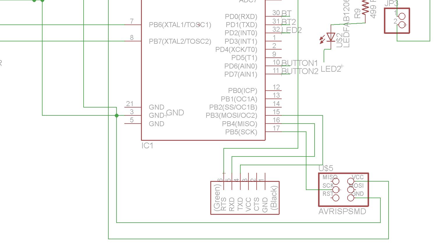
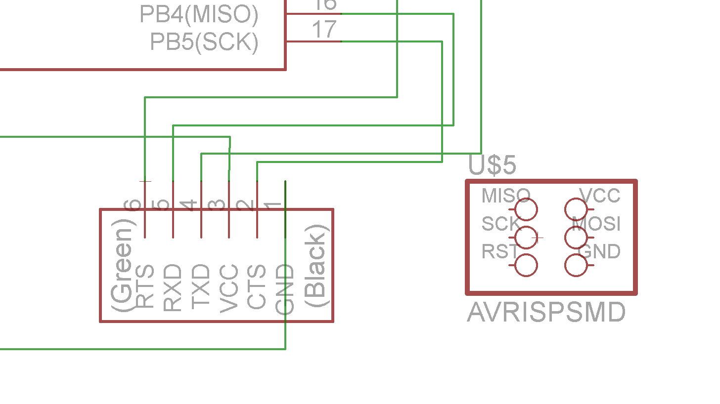
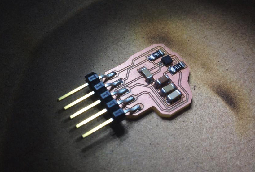
Also I let all the pin connectors to accelerometer and Bluetooth module to reduce error possibilities. Ones I burn bootloader in my main board I started to receive data in my computer by Bluetooth usefully. Then I unsold the pins connectors and some traces break out, fortunately those traces I did not needed any more.
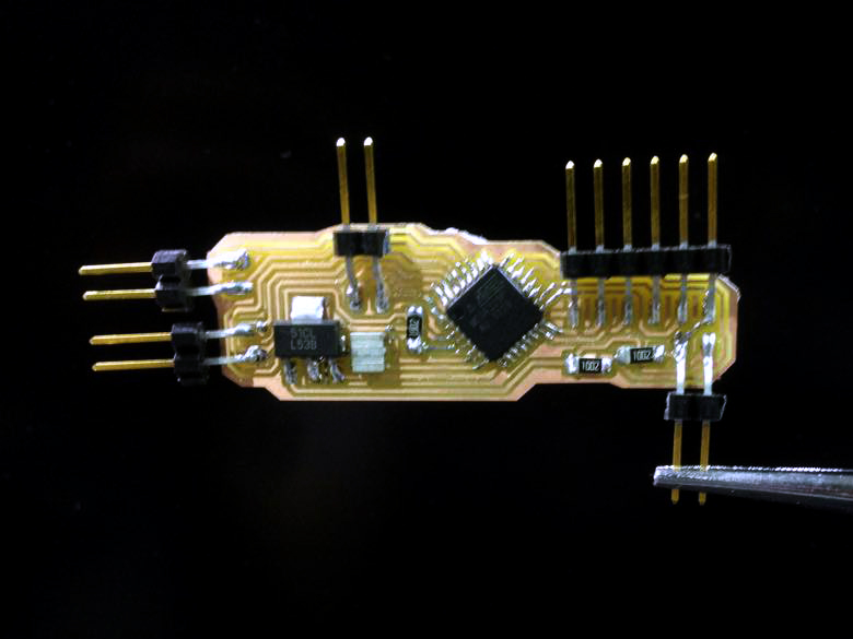
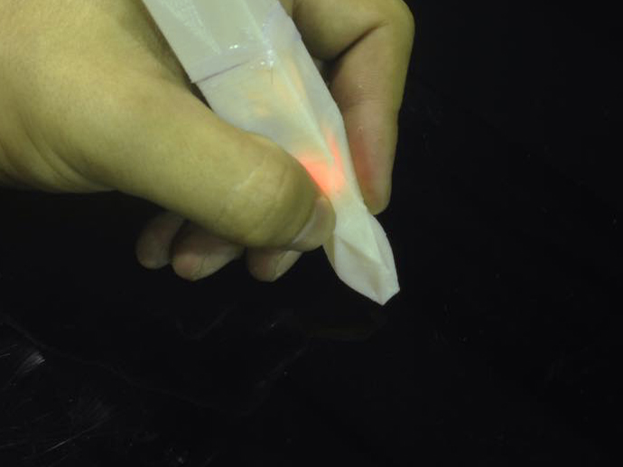
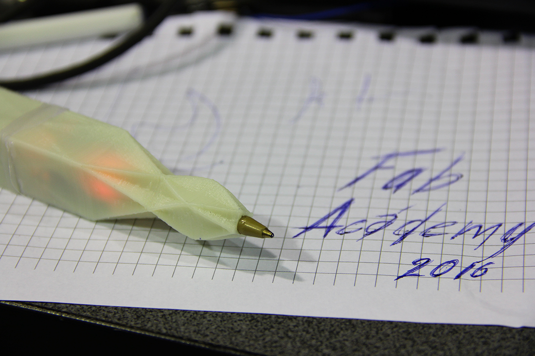
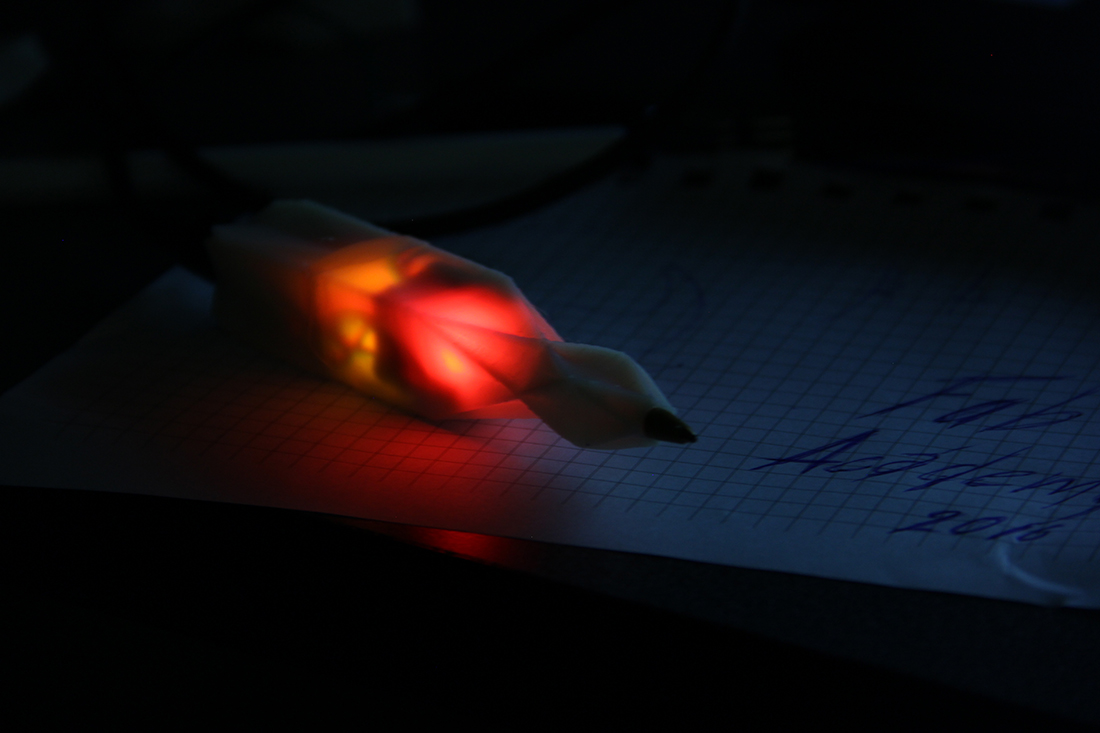
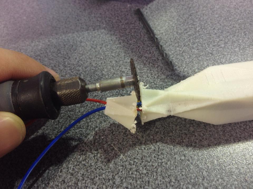
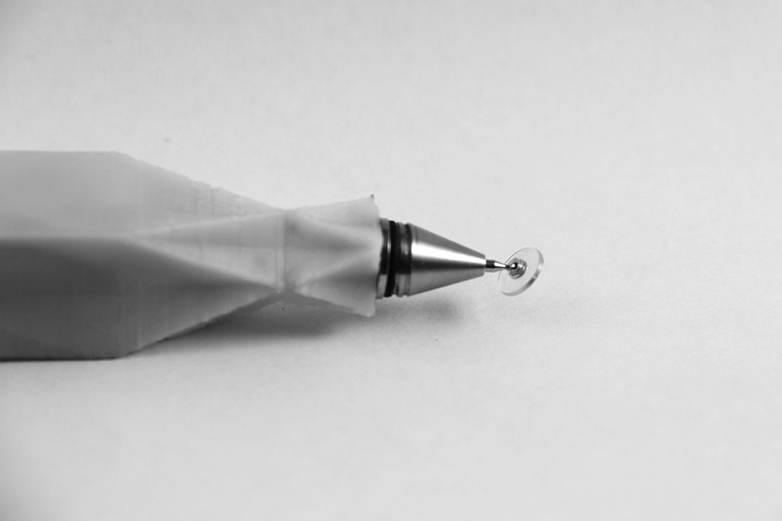
Furthermore I continued advancing pen design getting finished the digital nib of it. So, at this point I had atomic and digital functions working. I was looking to join data reception with processing vector program and G-code output machines
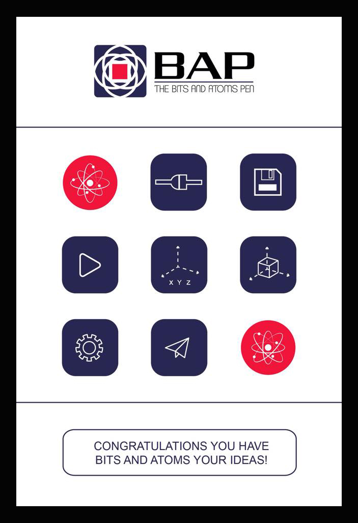
Currently, I had been developing the identity of analog and digital pen and the result from my creative process is BAP - The Bits and Atoms Pen. At the beginning I was thinking to call this project the Fab Pen but when I explore deeply I recognize that the essential of this object is Bits and Atoms theory rather than Fab Lab concept. BAP makes more sense to the identity of this pen and at the same time is a fundamental part of Fab Labs.
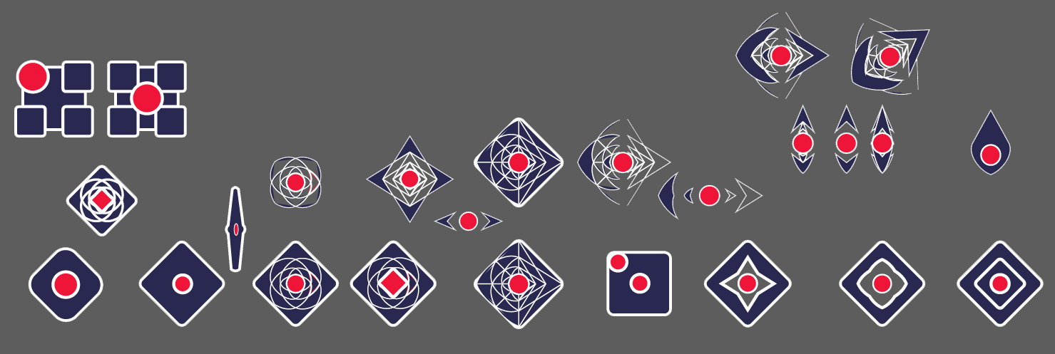
The logo process was quite hard to define because the morphologic concept of this product design is about how an atom could change his shape to transform in a bit and vice versa. Only in logo I spend 2 days to define something that was not planned. Then I continued with interface design of computer and cellphone application.
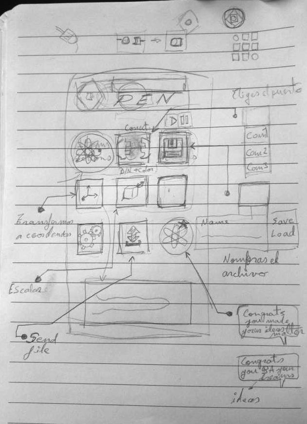
In this image is detailed the process that BAP application follows since searching active COM port until it gives you the G-code file to run to control Fab Lab machines.
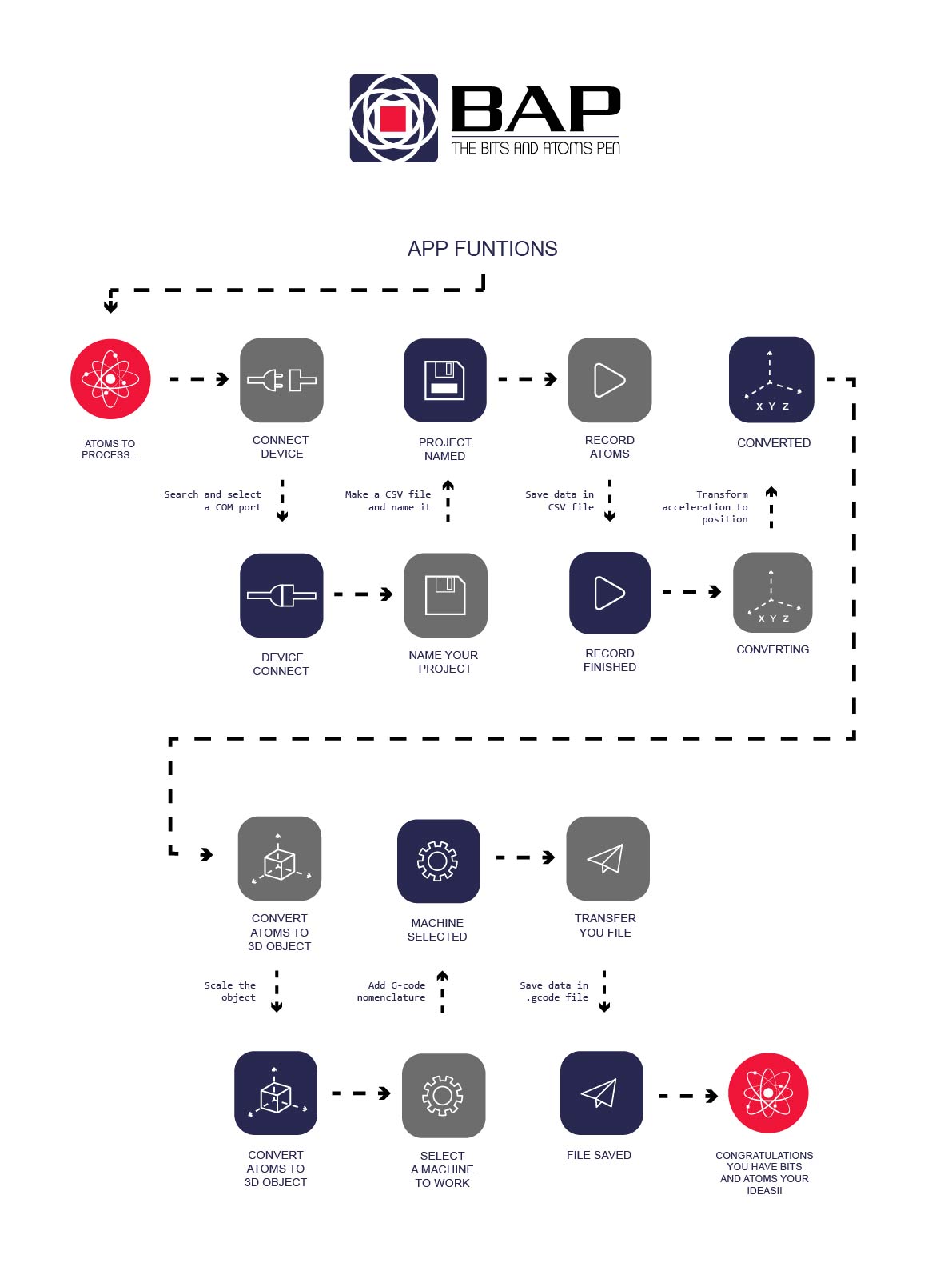
In order to see the Bits and Atoms Pen working Fabian Jimenez helps me to program an application in visual studio with main functions that I described in previous graphic.


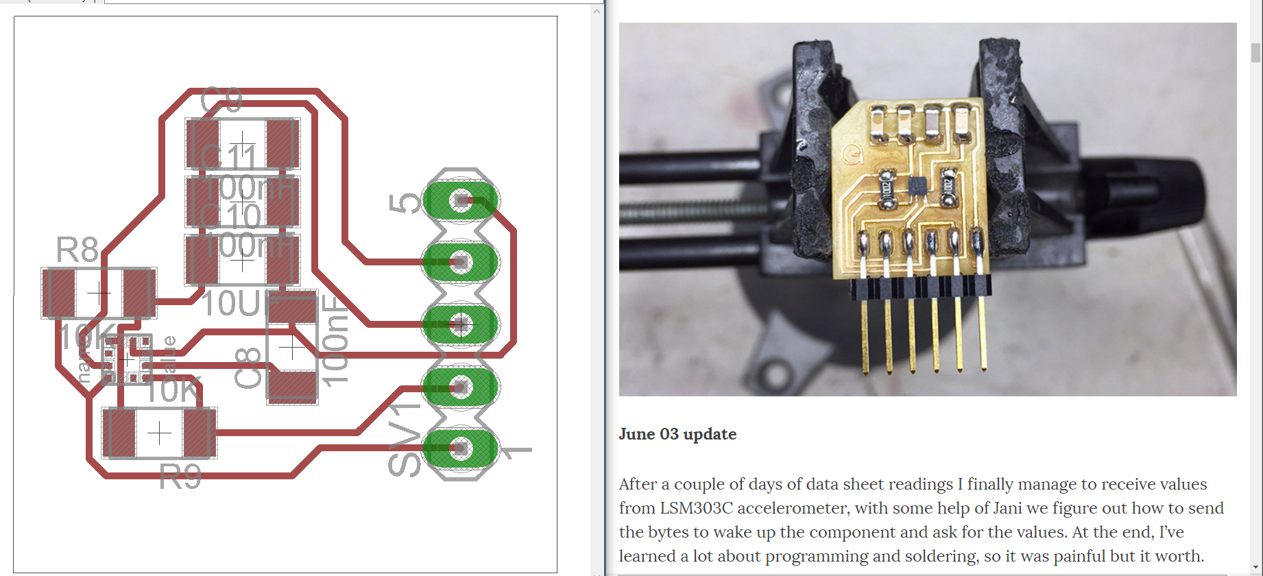
Time was short to complete all the idea but as Neil said spiral development was a really good option. In this third spiral loop I planned to add LSM303C accelerometer to my main in-circuit board as Gabriel Tanner did in his final project. Actually I based my accelerometer module in Gabriel’s one but I had some problems probably in soldering and the time just ended. Fortunately BAP modules were working and all was encapsulate. In order to make the video I used the vectos that pen gives me and I make others in aid-design software comparing with data that BAP generate and changing it when I looked necessary to preserve the precision of the line.


I have learned a lot in this project and now I feel that I am more prepared to make anything.
BAP is working really well and it has a great future.
BAP needs more developing in order to be a product, now is a grate prototype.
I am open to keep developing this project with more people. You are welcome to join www.bitsandatomspen.com.


The most complete program about digital fabrication raised in Boston. Fab Academy origins is the Bits and Atoms center of MIT that teach how to convert the physical world to a digital world and vice versa allowing you to modify it “to make almost anything”
FabLab Yachay is the first complete digital fabrication laboratory in Ecuador that is part of Yachay “the city of knowledge” how is motivated on creation and innovation to the country.
An independent Fab Lab that is partner of FabLab Yachay who find the opportunity to join efforts being part of Fab Academy 2016 in Yachay. ZOI is an innovation center in Quito city that is focusd on product design applying sustainable concepts

