3D Printing
- Index
- Making of FABISP casing
- CAD Models
- Printing process
- Download original files
- 3D Printer in Action
3D printing is the one of the rapid prototyping process, now a days it's becoming more and more popular because of the disruption of the technology. Plenty of 3D printer making kits are available with reasonable price tag, also with some basic knowledge you can build one for yourself with ease.
What is 3D printing?
According to Wikipedia3D printing, also known as additive manufacturing (AM), refers to various processes used to synthesize a three-dimensional object. In 3D printing, successive layers of material are formed under computer control to create an object. These objects can be of almost any shape or geometry and are produced from a 3D model or other electronic data source. A 3D printer is a type of industrial robot.
Why to 3D print? / Why not using subtractive manufacturing?
Subtractive manufacturing is the process of making an object by removing the material e.g. milling. Use of subtractive manufacturing is not valid in prototyping phase as it takes a lot of time and tool settings. Compared to the 3D printing making tool path, adjusting tool and loading material is the big task compared to additive manufacturing e.g. 3D printing.
My design is simple but making with subtractive manufacturing process will add additional steps of setting up toolpath and tools, as well as it creates lot of waste material which we need to throw.
3D printing is one of the rapid prototyping process which involves the plastic like substance technically ABS or PLA majortly found in these FDM printers. The process of 3D printing is chosen over molding and casting as it takes very less efforts to realize the model. Rather than putting efforts on making mold and casting it one can directly command printer to print a 3D object right from his 3D designing software.
The time involved in the process of making mold and cast it is very large as compared to 3D printing hence printing is preferable for prototyping. But when it comes to manufactureing or mass production 3D printing is not at all useful. The invention of the 3D printer is for testing your proposed model that is prototyping only.
Making of FABISP casing
In this assignment I'll be creating a casing for FABISP kit.
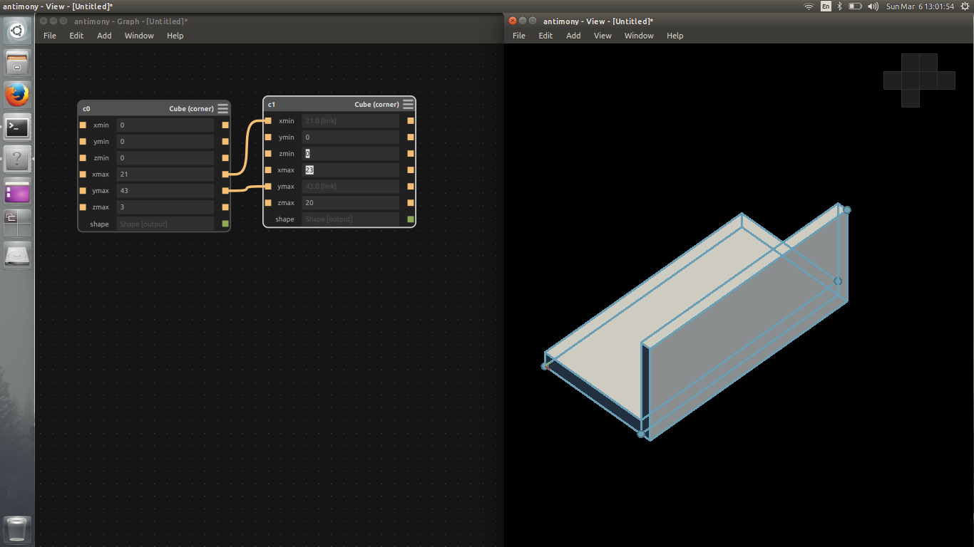
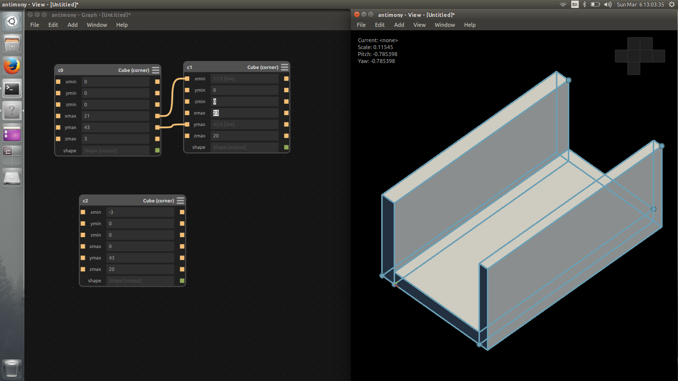
Designing is the process pf combining multiple rectangles together. In screenshots above you can see the program for creating the rectangle in Antimony. Antimony is the parametric designing software. Parametric means change is one parameter leads to uniform change in design without spoiling the structure. That means I can scale up and down the design just with change in A parameter. That's the beauty of Antimony.
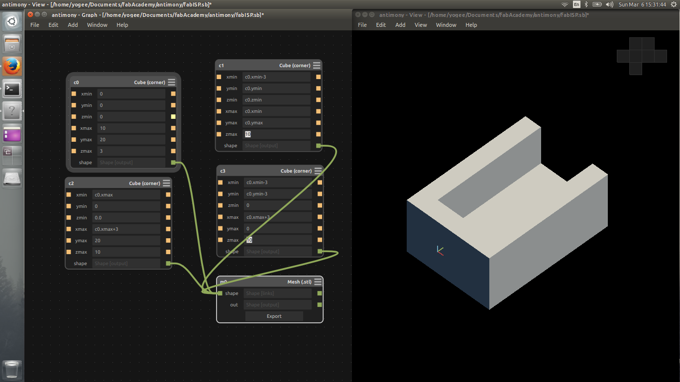
Here everything of positioned with respect to other object co-ordinates this methodology makes the design parametric.
CAD Models
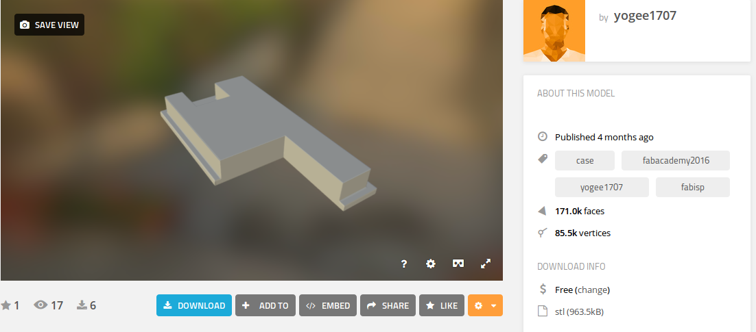
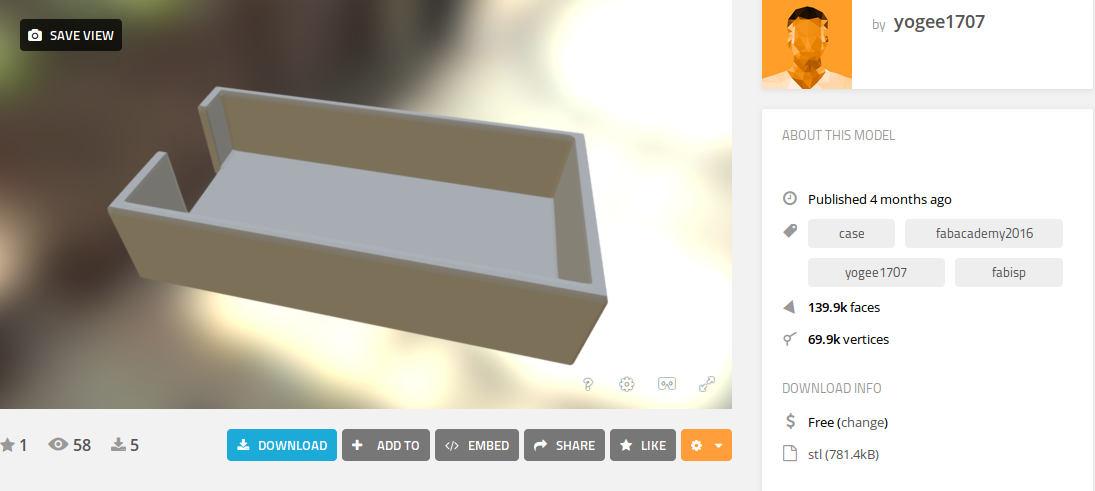
I've added these screenshot for those who are not connected to internet as you won't be able to see the content as it is iframe taking data directly from Sketchfab
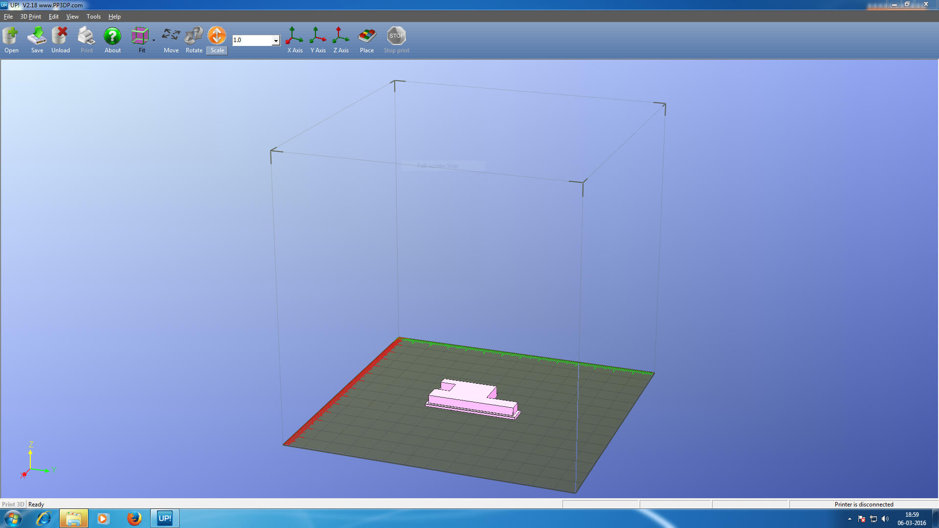
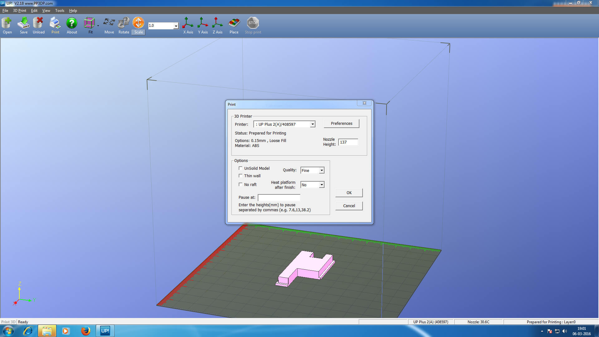
Printing process

I imported the file in the machine software for UP printer. There are plenty of tools available to set the object properly on the printing plate. If I fail to do proper alignment object(s) may not be properly printed. Or may be extra support material is added if the object is in the mid air while placing it. To avoid all these mistake this software provide the function of auto-placing the design file on the print bed.
Comparing the results
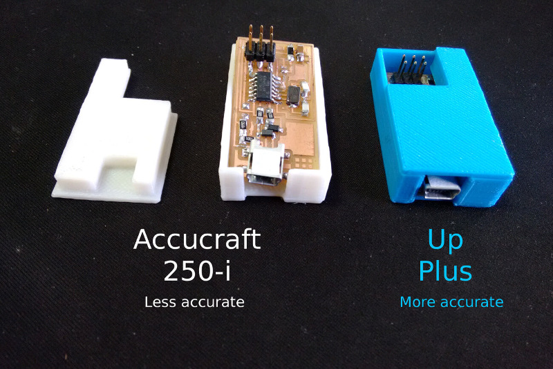
I've loaded the same stl files into both the machines. The above result I got.
My Observations
- Up printer performed better
- The time taken by Accucraft 250-i (~35 mins) is less compared to the Up Plus (~42 mins)
- Both machines have used same material i.e. ABS
3D Printer in Action
Here I've attached the video which I shot while printer is busy...
Problems
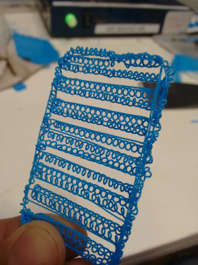
The picture attached beside shows the what printer did first time when I tried to print the base of my FAB ISP case. As I saw the printer is not printing properly I turned off printing Here are my suspects,
- I've not placed the object in machine software correctly, because of which printer tried to bridge the gap by creating support structure.
- Bed leveling is not properly done.
Solved:
After this I did bed leveling using 9 point calibration option which I found in the machine software. This helped me to resolve the problem. 9 point calibration is done using sensor which senses whether the bed is touching the sensor tip or not, 9 points are equidistant on the square shape bed of up plus, arranged in 3x3 matrix.