This week is about output devices, thing which give out some recognizable output. Neil in his videos explained a variety of them, you can view it here. I have worked with some standard modules available for modular board like arduino. Really excited to make something of my own.
After thorough thinking, i have decided to make the relay circuit needed for my final project. I have a spare 250v 6A, 5V SPDT relay with me. So decided to make a control circuit and a drive circuit for the same.
About Relay
Relay is an electrically activated switch ie, it can be switched ON and OFF using just electric signals. I have a Single Pole Double Throw or simply SPDT relay. It has five terminals one common pin one normally closed (NO) pin, one Normally Closed (NC) pin and one pin for giving the control pulse and one ground pin. The common pin and the NC will be closed when idle, but when a pulse is given across the coil it will become open and the NC and common pin become close. So we should make the connections accordingly.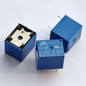
The design
Rather than driving the mechanical relay directly from the microcontroller i will have a driving circuit for the same. For final project i will be using a Atmega 328p microcontoller and it would be hard to drive the relay directly by it. I have planned to have the final project done in modular ie, I will have a controller board, a board for wifi connectivity, relay board etc. So here is what i have designed for the relay board. It has an npn transistor biased in the switching mode with the coil of the relay connected to the collector terminal.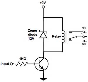
The schematic represenation in eagle is 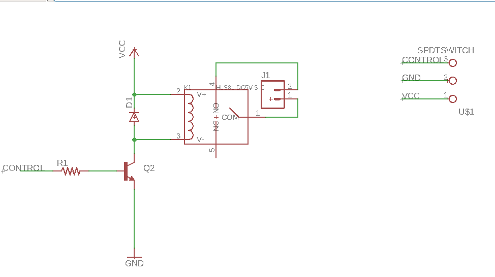
The board layed out in eage is 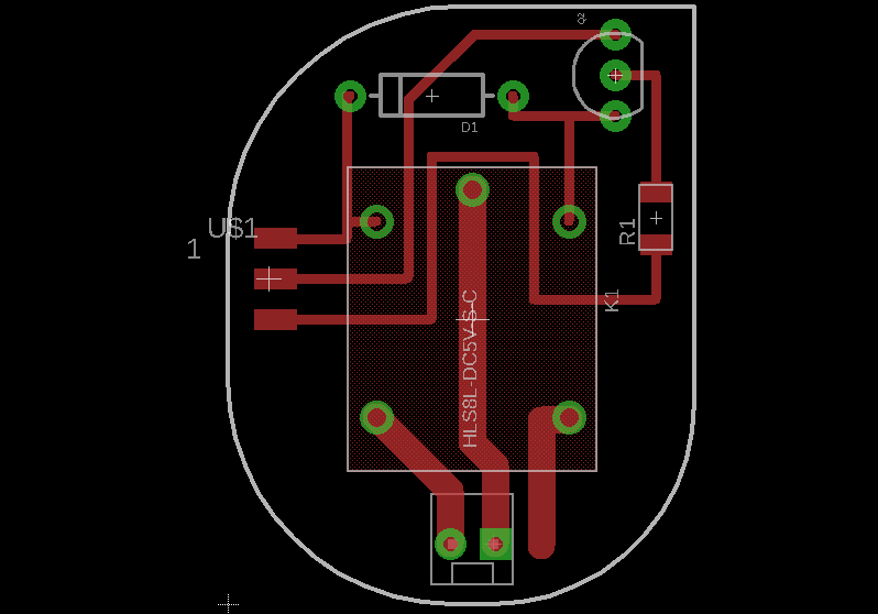
On can can observe that pads are left for th controller to communicate with the relay. It is good for switching AC loads up-to 250V, and that is exactly what I need.
The finished relay board 
I have designed a separate controller board for operating the relay. As I mentioned before, relay is part of my final project and there I have separate controller and wifi boards. Here is the schematic of my controller board and the code is written for switching the relay when ‘ON’ command is received wirelessly through wifi.

1 | #include <WiFiEsp.h> |
You can see that pin 7 is connected to the relay. VCC and GND are also passed on to the relay circuit.

Parallel Attempt
The weeks assignment has been put into a project for detecting hypothermia during neonatal care. I came across the wonderful product by “Bempu” which is my inspiration for doing this project. I will try to make a similar one with the materials available in our lab.
Aim
To make the device with the following
- A thermistor for monitoring the temperature.
- An LED to indicate the status. Will blink with varying speeds according to the situation.
- To have a battery strapped to it for power.
- Molding and casting for making the body of the watch.
- Probably some reinforcement while making the bracelet.
Input and output side
We have thermistors, both NTC and PTC, , and I chose NTC. Keeping Neils hello.temp as reference I made a board which has the mechanism to sense and monitor temperature. I also added an led for the time being as an indicator. The LED will blink rapidly when the temperature goes below a certain level.


In the final stage I am going to add a buzzer along with the LED which could give out a alarm beep when necessary.
The logic part
Thermistor is something that changes resistance with change in temperature. With NTC the resistance drops with increase in temperature. the math d says the relation between the change in temperature and change in resistance in non-linear but exponential. There are different equations and chose the Beta equation which is as follows

So from the data sheet of the thermistor I am using I can get all the necessary values of the constants that comes in the equation. Here R(25) = 10000 & B(25/85) = 3750.
We have the thermistor at one of the branches of a bridge circuit. The ADC’s are connected to the bridge to monitor the voltage fluctuations.
The board is inspired from hello.temp, and the AVR-C code is derivative of Neil’s coode for the same. I have changed the purpose of the board from sending the data to the computer through FTDI to blinking an LED when the temperature is below 25C ,which is the critical low temp of for hypothermia. I have included the processing of the ADC output in the chip itself enabling it to function independently. Apart from that I have changed the ADC from bipolar differential, as in the original code, to unipolar differential code. Here is my code
1 | // hello.temp.45.c |
Your browser does not support the video tag.
Work to be done
- in place of the LED have a buzzer to sound alarm.
- make a bracelet, probably mold or cast, which can hold the sensor.