
COMPUTER CONTROLLED CUTTING
This week is dedicated for computer controlled cutting. We are learing to use the following machines,
Learn how to make a Press Fit joint ( Do a parametric design and Try on different materials with different dimensions )
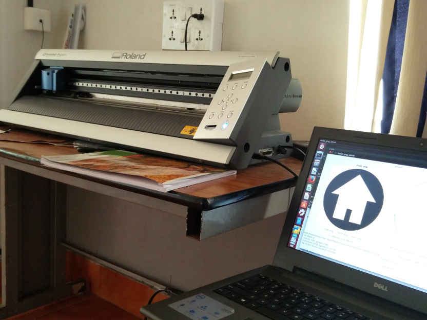
VINYL CUTTER
Vinyl cutters are used to create 2D Stickers and also flexible PCBS in the FABLAB.The stickers to cut should only have two colours ( Black & White) , this is to make sure that there is a clear contrast between the two colours in the boundary. ( ie the sufraces to be cut ) The recommended resolution of the pictures is 500PPi , ie 200Pi/CM. Here we only use pictures in the PNG format.
Setting Up The Vinyl Cutter
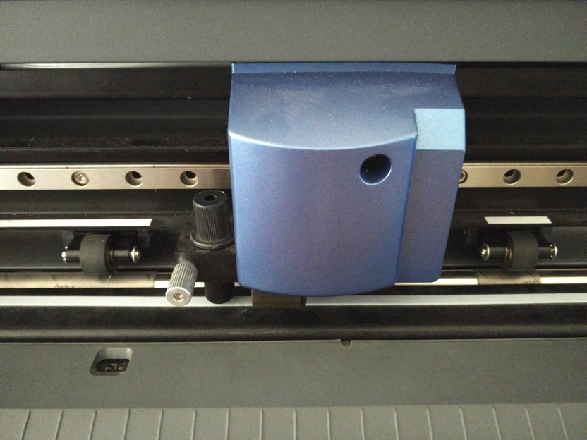
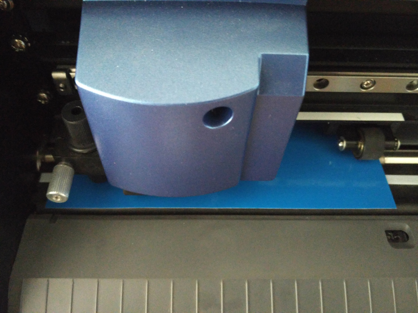
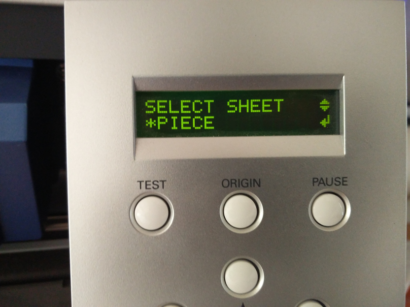
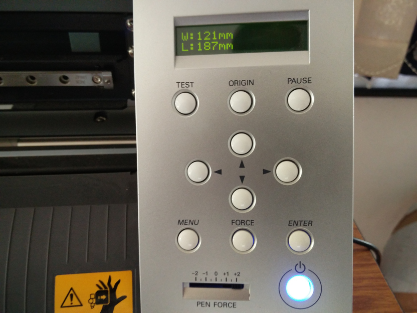
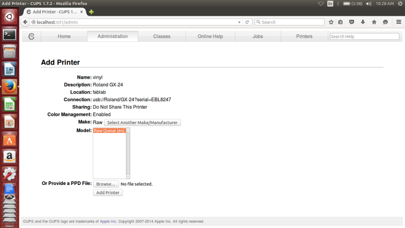
Now its time to switch over to the software, follow the procedure to set up the cutter for the first time,
A PREFAB STORY - Flashback playing with Vinyl Cutter
This time I did not experince any difficulty during the test cut, but always the story cannot be the same, there can be number of reasons due to which the Test cut can go wrong, THIS LINK takes you to such an experiance I had during my prefab which I felt is worth mentioning.
Moving ON..
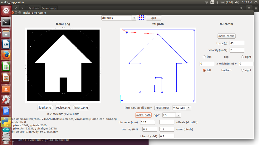
Now the Test Cut is being sucessful, open the Vinly Cutter fab software interface for the desired job,
Go to Terminal --> fab
In the menu that pops up, follow the instuctions as described..
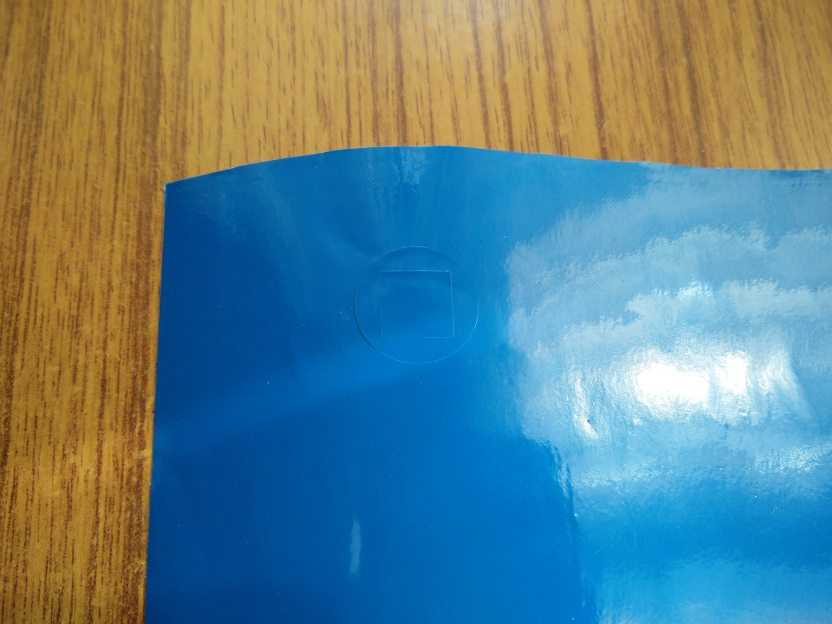
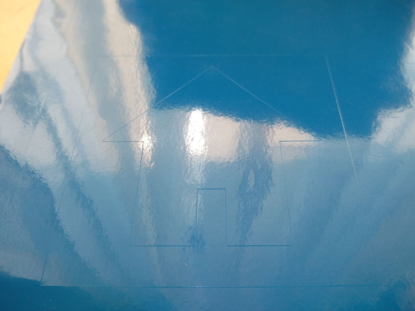
The following pic shows the cut sticker.
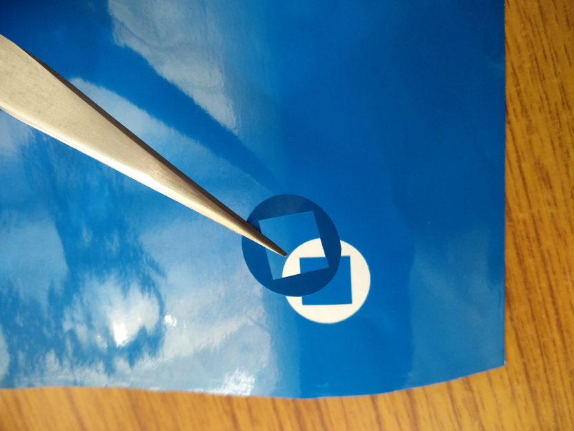
To transfer and stick the sticker to the desired surface, a clear tape is placed on top of the newly printed sticker. The Idea behind this is to take out the desired part of the sticker alone by peeling it carefully.

The design file used for this process can be downloaded from here.
FLEXIBLE PCB USING VINYL CUTTER
One of the most important applications we can make use of Vinyl cutter is to print Flexible PCBs, the next thing I am going to try is to make one of this as time permits and will update here.
PRESS FIT Joint Using Laser Cutter
Laser cutter is one of the most sophisticated as well as costly machine we have in fablab. Unlike most other machines, Laser cutter can not be left unattended. It needs continuous monitoring during the time of work. It deals with extreme amounts of heat and hence a constant vigil is necessary to avoid any sorts of hazard that can be caused due to fire.
I will be documenting two examples for the time being with Laser Cutter

1. A SIMPLE Box Using Laser Cutting
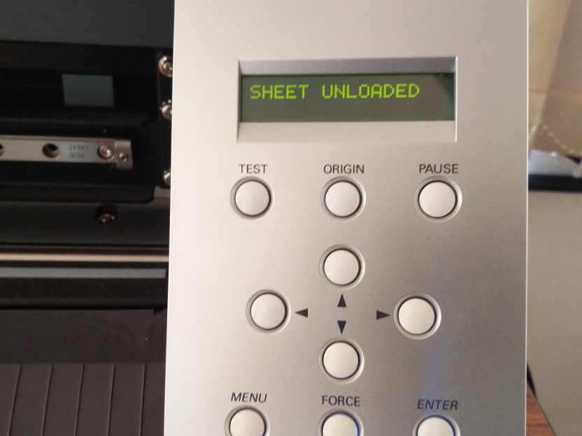
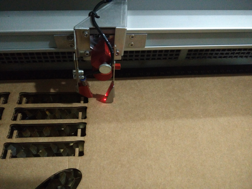
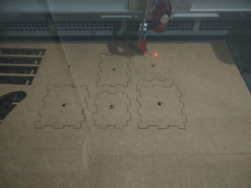
The first thing to do is to make sure that the exhaust system of the lasercutter is turned ON and is working perfectly. Now load the required material. Make sure that it is held flat on the bed inside. You can see a red spot light indicating the current head position. This is not the actual high power laser beam used to cut and engrave, but it is used as a guiding reference to position the head.
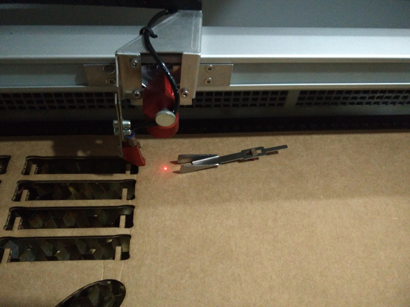
Focous the laser beam using the focousing tool as shown below..
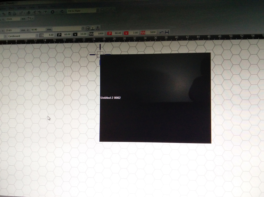
Once you give print from the design software ( Here I have used coral draw to open my .SVG file created in Inkscape ) it sends the data to the Trotec Job Control software
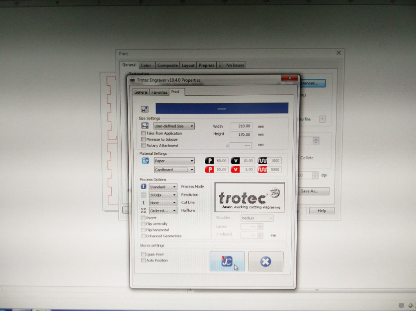
You can preview the part to be cut using the Job Control software itself.
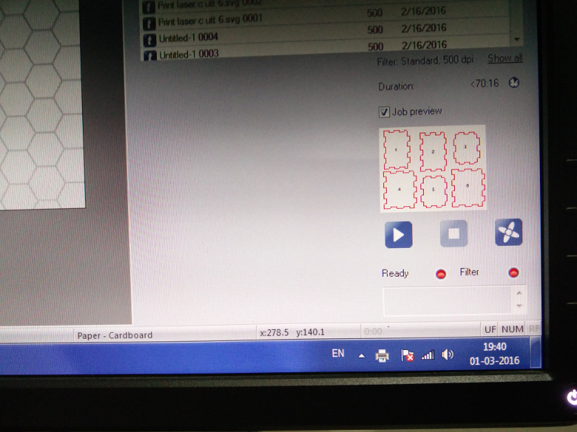
You can preview the print position as shown below and the corresponding head position can be tracked on the screen. Once the required parameters are set give ready.
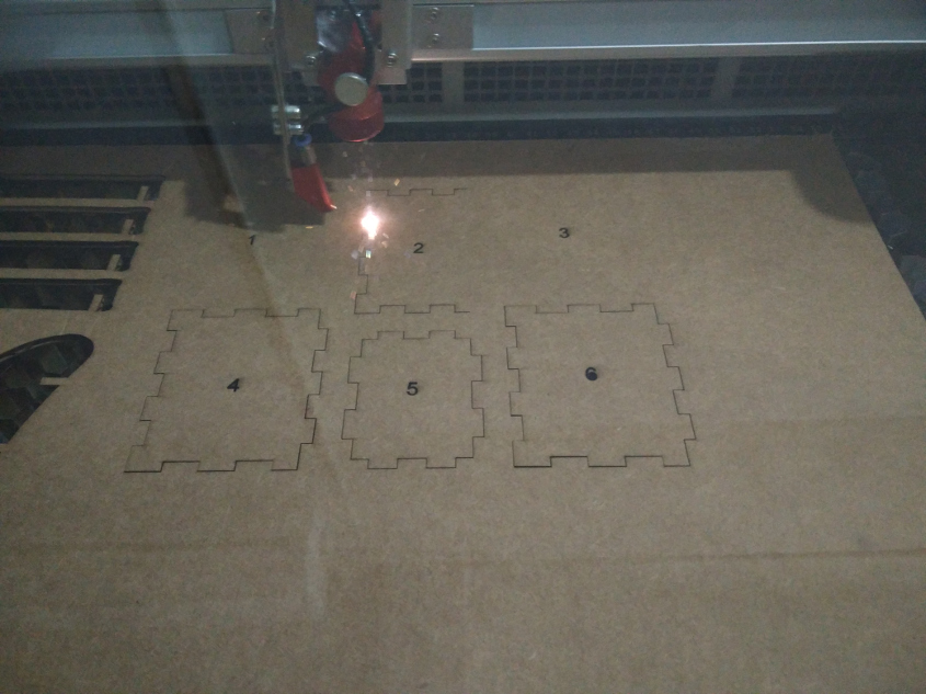
Laser cutter in action..
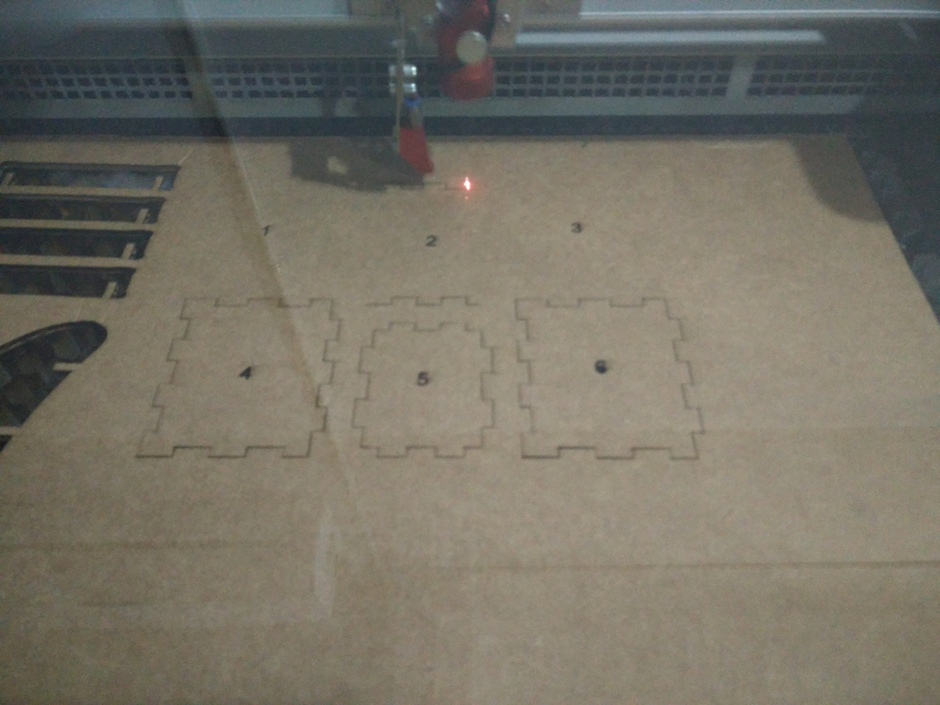
Laser cutter in action..
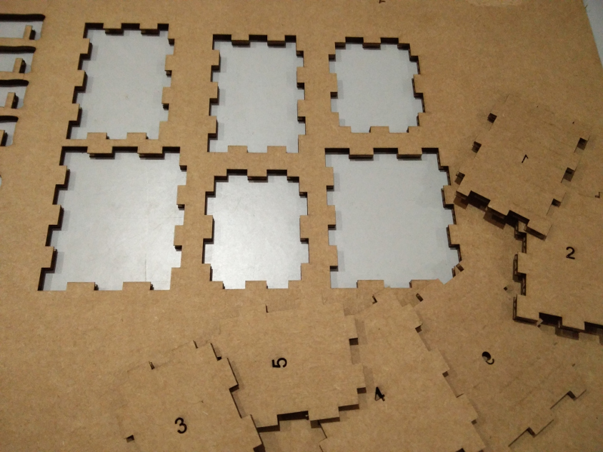
The Cut and engraved pieces
Laser cutter in action..
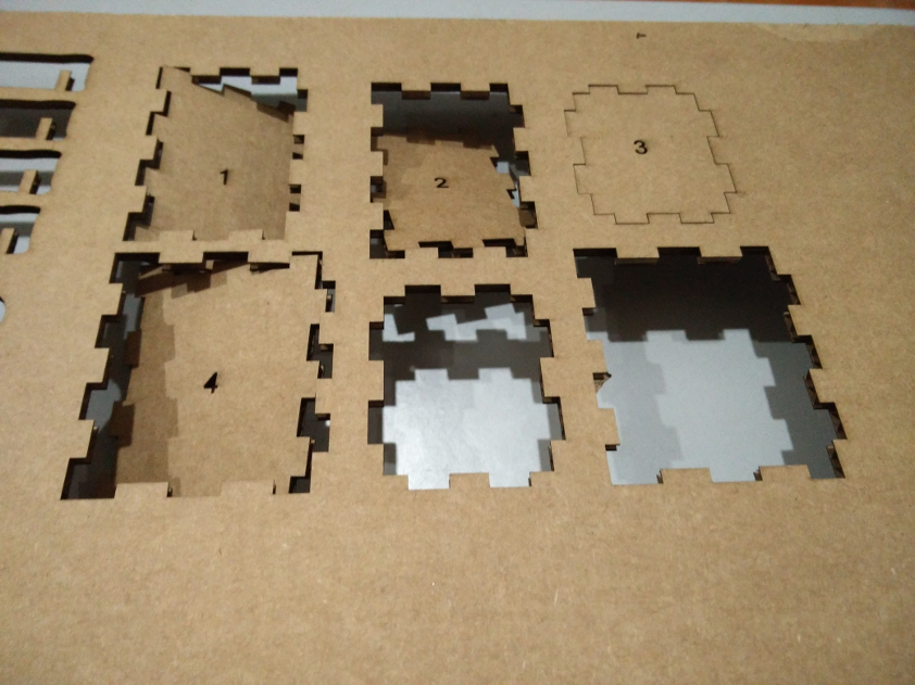
As it can be seen the power for engraving seems to be litter higer and the laser has cut through the cardboard, though only engraving was intented.
The finished box
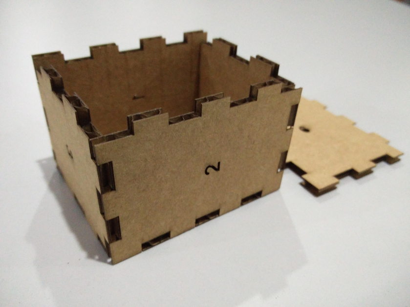
The finished box
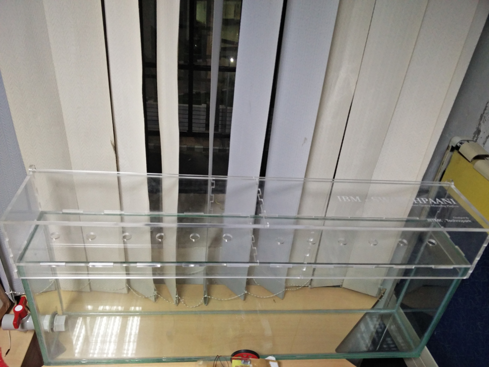
2. ENCLOSURE FOR Final Project
I wanted to make an enclosure for my final project. My requirement is to make a box that has to Host my electronnics and at the same time provide acess to the sensors which will be floating beneath the box on water. And I misssed to tell you , the project is all about a water quality measurement . So I am making a platform for the same.
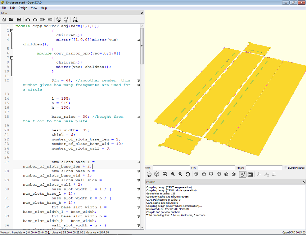
The box design is made in OpenSCAD softwre. This was suggested by Sibu , who has been workig on OpenSCAD. I was facinated by his codes from which he made professionally looking boxes, this inspired me to work with him on this enclosure's design.
OpenSCAD Software
OpenSCAD is a software for creating solid 3D CAD models. It is free software and available for Linux/UNIX, Windows and Mac OS X. Unlike most free software for creating 3D models (such as Blender) it does not focus on the artistic aspects of 3D modelling but instead on the CAD aspects. Thus it might be the application you are looking for when you are planning to create 3D models of machine parts but pretty sure is not what you are looking for when you are more interested in creating computer-animated movies.
OpenSCAD is not an interactive modeller. Instead it is something like a 3D-compiler that reads in a script file that describes the object and renders the 3D model from this script file. This gives you (the designer) full control over the modelling process and enables you to easily change any step in the modelling process or make designs that are defined by configurable parameters.
OpenSCAD provides two main modelling techniques: First there is constructive solid geometry (aka CSG) and second there is extrusion of 2D outlines. As data exchange format format for this 2D outlines Autocad DXF files are used. In addition to 2D paths for extrusion it is also possible to read design parameters from DXF files. Besides DXF files OpenSCAD can read and create 3D models in the STL and OFF file formats.
The best part is that the design is parametric and any sort of scaling can be done without much difficulty..
Design in OpenSCAD..
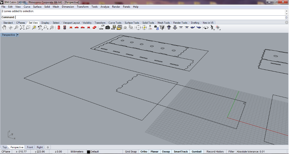
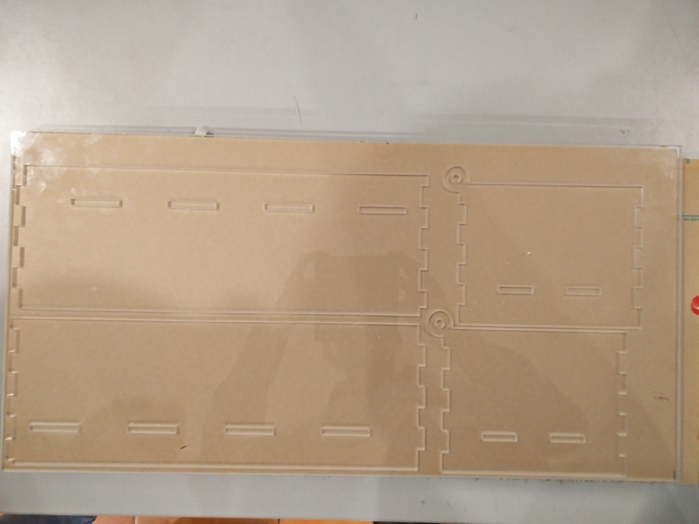
Design modificaitons in Rhino to add holes and to trim the design to the laser bed size..
Cutting finished..
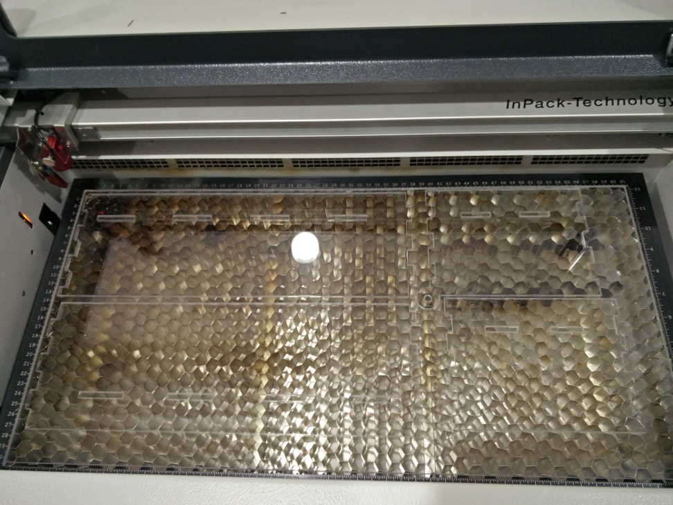
Finished cut pieces..
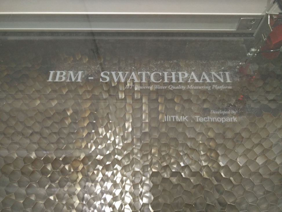
Engraving in progress..
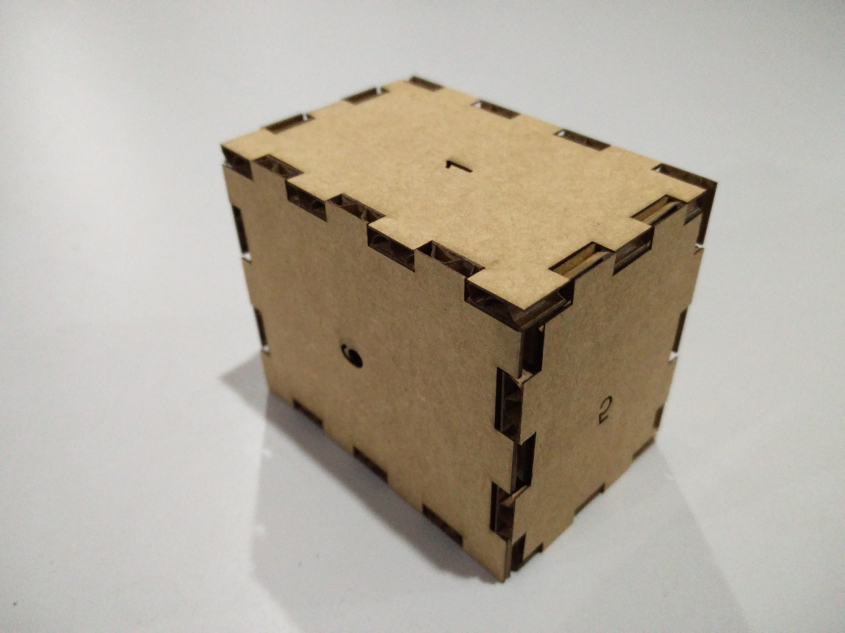
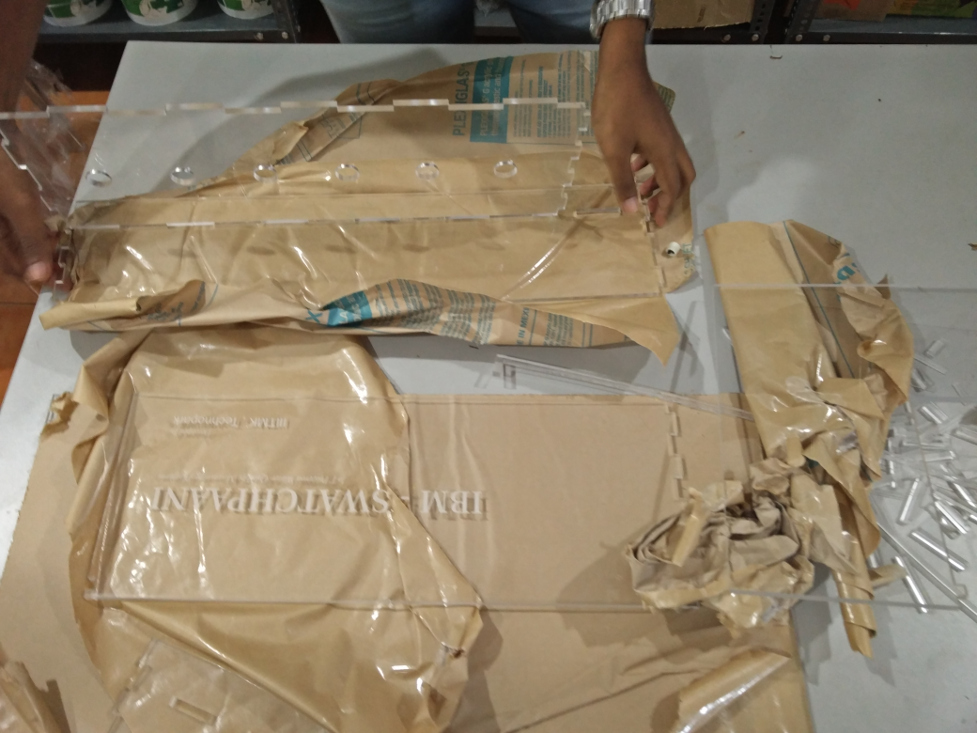
Fixing them together..
Complety Finished Enclosure
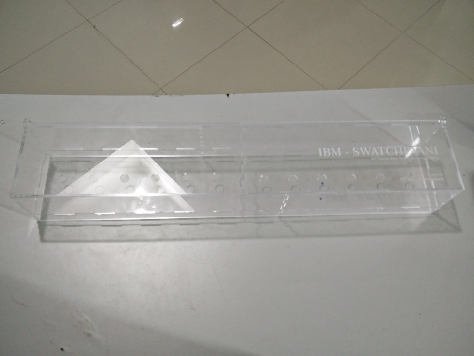
A perfect Fit on top :-)
The design files can be downloaded from here.