
3D Scanning and Printing
The assignment for this week is to test the 3D printer limits and print something that can't be made subtractively, and 3D scan an object.
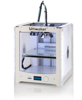
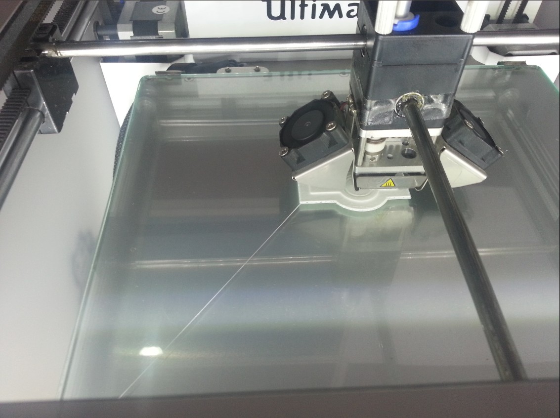
The 3D printer we have in our lab is Ultimaker 2.
Testing the printer limitation
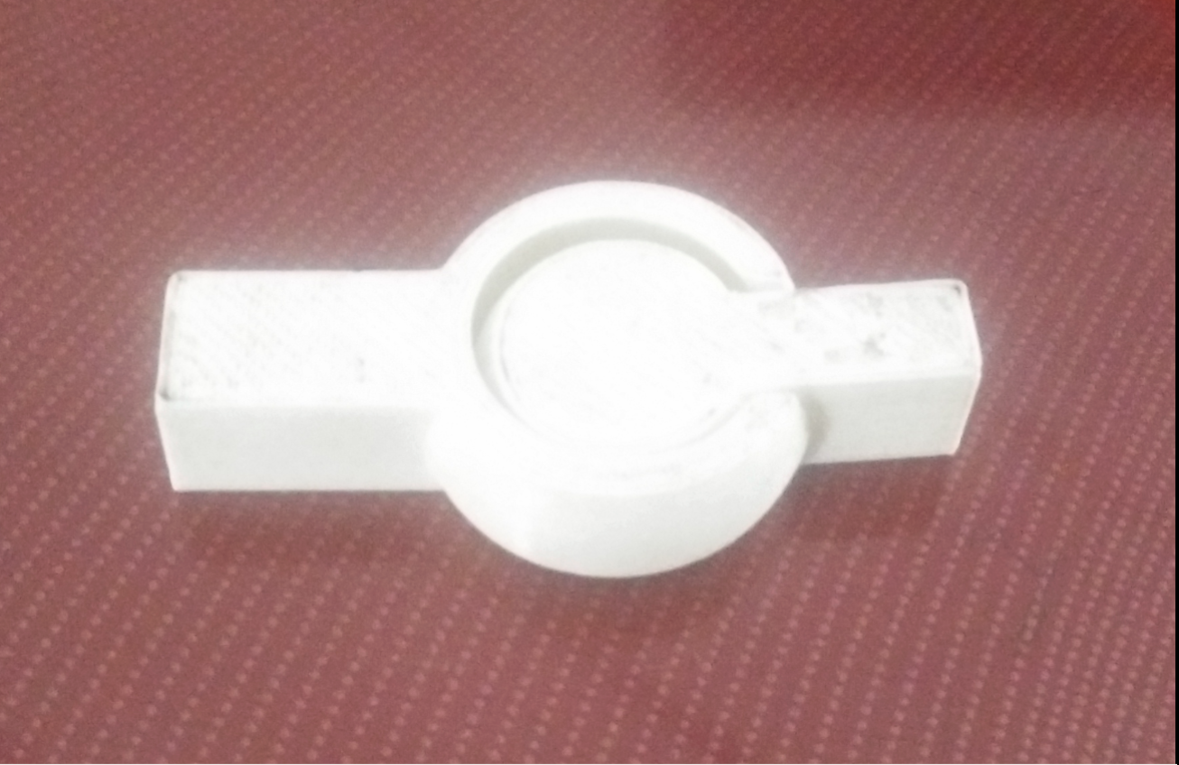
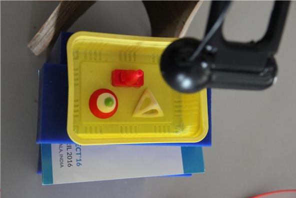
For testing the 3D printer what we have done is we printed an object which contains many shapes like circles, angles, gaps etc. By cross checking the original shapes measurements and printed shapes measurements, we can understand how precise our printer is. We downloaded that design from thingiverseLink to thingiverse
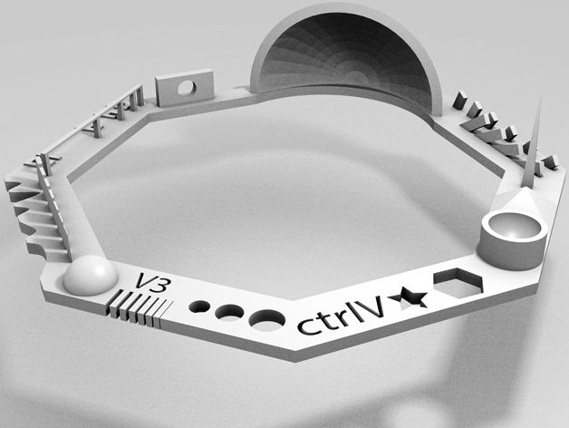
Print design
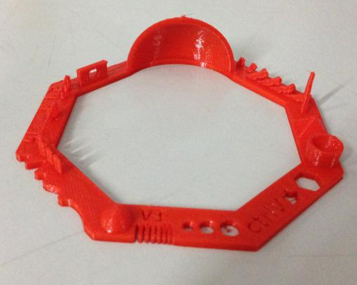
Here is the printed object.
The shapes included in the design are
01 Nut, Size M4 Nut should fit perfectly
02 Wave, rounded print
03 Star, Sharp Edges
04 Name, Complex Shapes
05 Holes, Size 3, 4, 5 mm
06 minimal Distance: 0.1, 0.2, 0.3, 0.4, 0.5, 0.6, 0.7 mm
07 Z height: 0.1, 0.2, 0.3, 0.4, 0.5, 0.6, 0.7, 0.8, 0.9, 1.0, 1.1 mm
08 Wall Thickness: 0.1, 0.2, 0.3, 0.4, 0.5, 0.6, 0.7 mm
09 Bridge Print: 2, 4, 8, 16 mm
10 Sphere, Rounded Print 4.8mm height
11 Sphere Mix, 7 mm height
12 Pyramide, 7 mm height
13 Overhang: 25, 30, 35, 40, 45, 50, 55, 60, 65, 70°
14 Warp, does it bend?
15 3D Print Font, optimized for 3D printing
16 Surface, Flatness
17 Size, 100 x 100mm x 23.83 (10mm width)
18 Spike, minimum Layer Time, 21 mm height from Bottom (include Baseplate)
19 Hole in Wall, 4 mm diameter, check for proper print
20 Raft Test, raft should be just under the model
21 Retract Travel, check retract settings for longer travel
By observing the printed object, the problem/limitations in the printing are:
3D Printing
Next assignment is to design and print something which can't be made subtractively. My ideas was to make a joint. I used rhino for the design..png)
.png)
.png)
.png)
.png)
.png)
Joint by yadusharon on Sketchfab
I exported it as .stl file and I used cura for making the gcode.
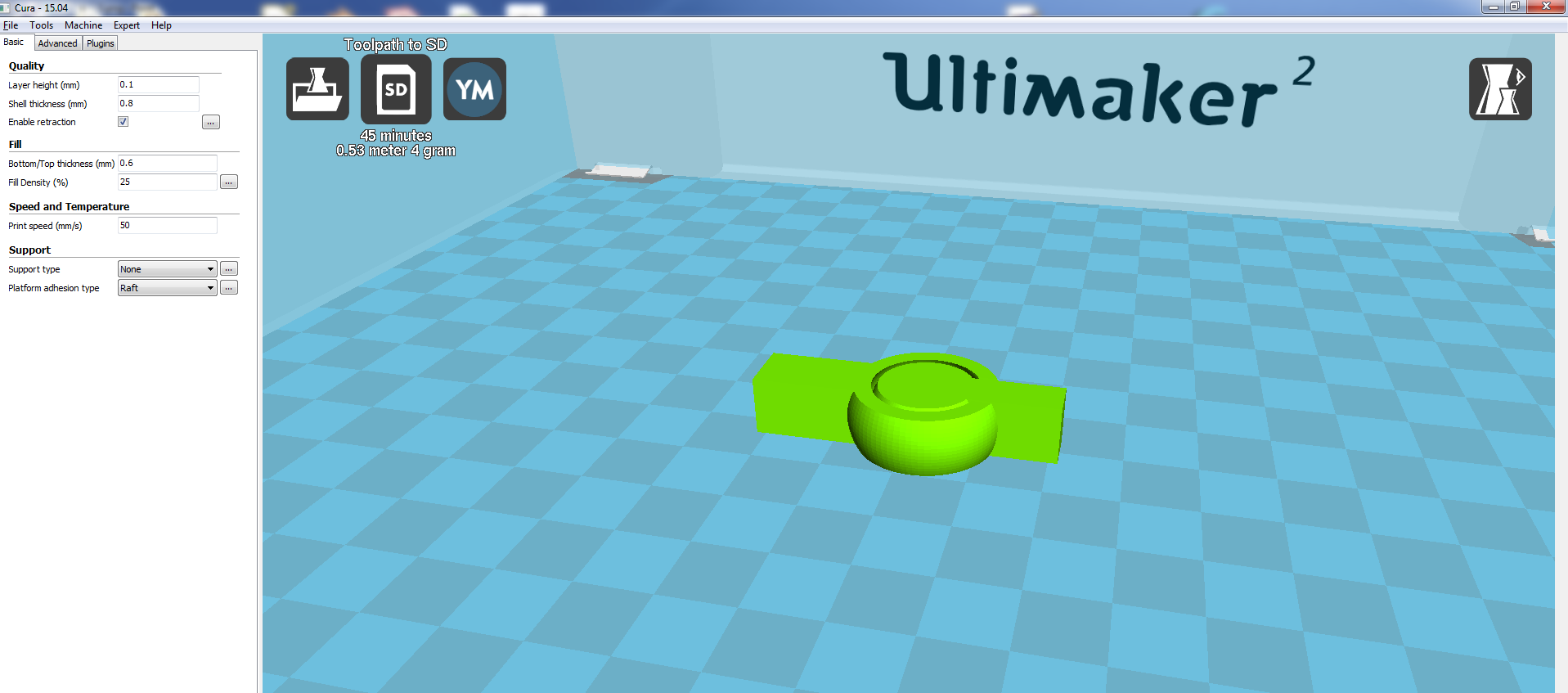
The parameters i gave are :
    Quality
    Layer hight : 0.1 mm
    Shell thickness :0.8mm

    Fill
    Bottom/top thickness : 0.6mm
    Fill density : 25%

    Speed
    Print speed : 50 mm/s
This is the final product:
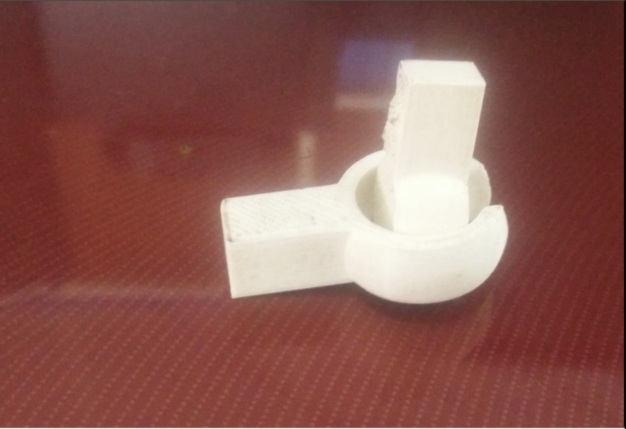
You can download the original files here : Rhino file .stl file.
Another thing I deigned which can't be made subtractively is a 4D Fkask, a version of Klein bottle. This is something similiar to Mobius strip. What i designed is a 3D projection of the 4D object. I couldn't print because the printer was very buzy those days. But I just designed it. I designed it inspired from a session on Fourth Dimensional Maths by Matt Parker. The video is very interesting and. You can see the video and the flask in real.
4D Flask by yadusharon on Sketchfab
3D Scannig
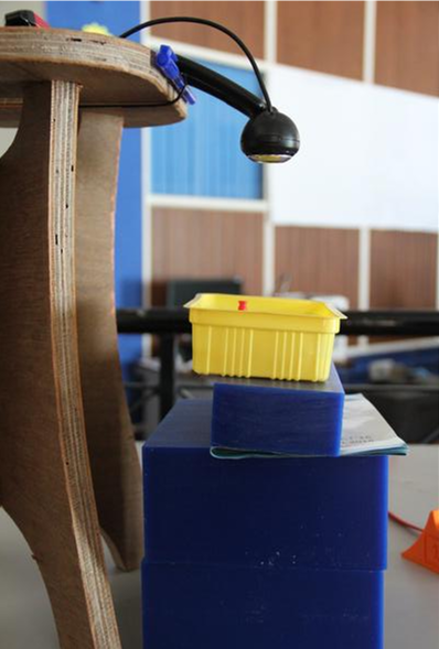
For the 3D scanning assignment I was planning to make a fluid canner as a group assignment with Vishnu and Sibu. The requirements are an opaque liquid, here we are planning to use a the fabric paint available in the lab, a pot , a web camera and a PC. Refer here for more details. The software for windows and mac are available there.More instructions are available in the instructable page. See the setup below:
Here is the .xml file.
3D Scanning using Modella
In most cases modella is used as modelling machine rather than a scanning machine. It has a separate end effector for scanning, whrer the normal milling end effector is to be replaced with this. I wanted to test scanning by modella thoug it will take a lot of time.The first step is to remove the milling end effector.
This is the end effector for scanning.
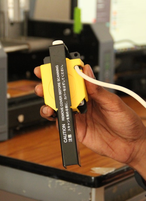
Mount it at the same place and plug the cable to the same socket.
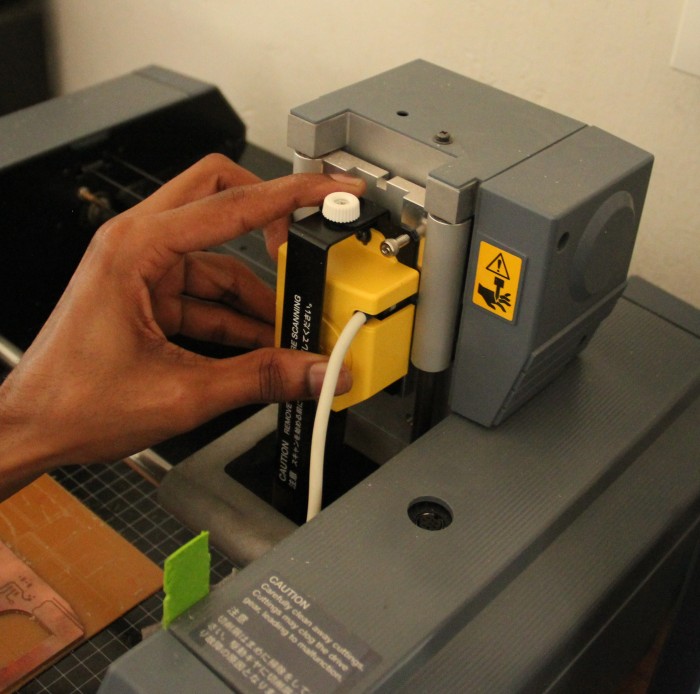
Remove the black cover so that you will see a metal needle.
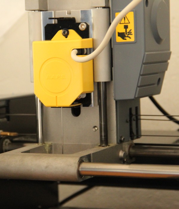
Place the object to be scanned on the bed. Stick it using a double sided tap.
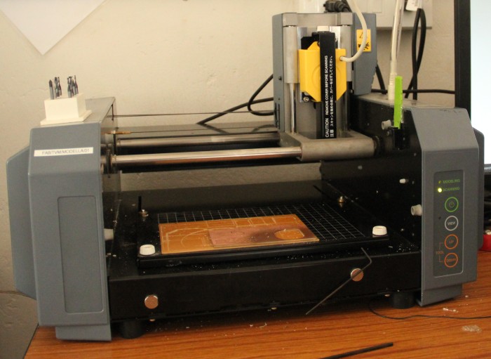
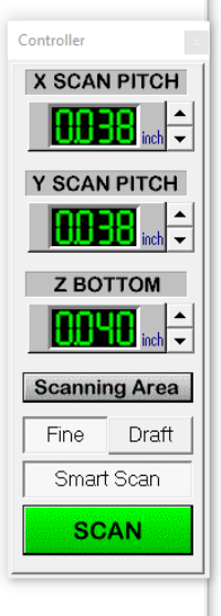
So the hardware part is ready. Next we have to open the Dr.PICZA. I opened it in windows i couldn't find any tool for Linux. Once you open you can see a box at the right side showing the X, Y, and Z pitches. First wee need to set the scan area. Becasue we will be usinh a small area, no need to scan the area where no object is not placed.
Click on the " Scanning Area"
Now select the scanning area. To test, click on the "Begin Area Test" and change the area according to that. Change the Z bottom value so that the needle touches the bottom plane where the object is places.
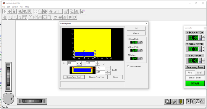
Press ok when it is done.
Now the area is set and we can start scanning. Click on "SCAN"
Now it will start scanning. It will take bit time.
See the canned 3D image. We can export it as .stl file.
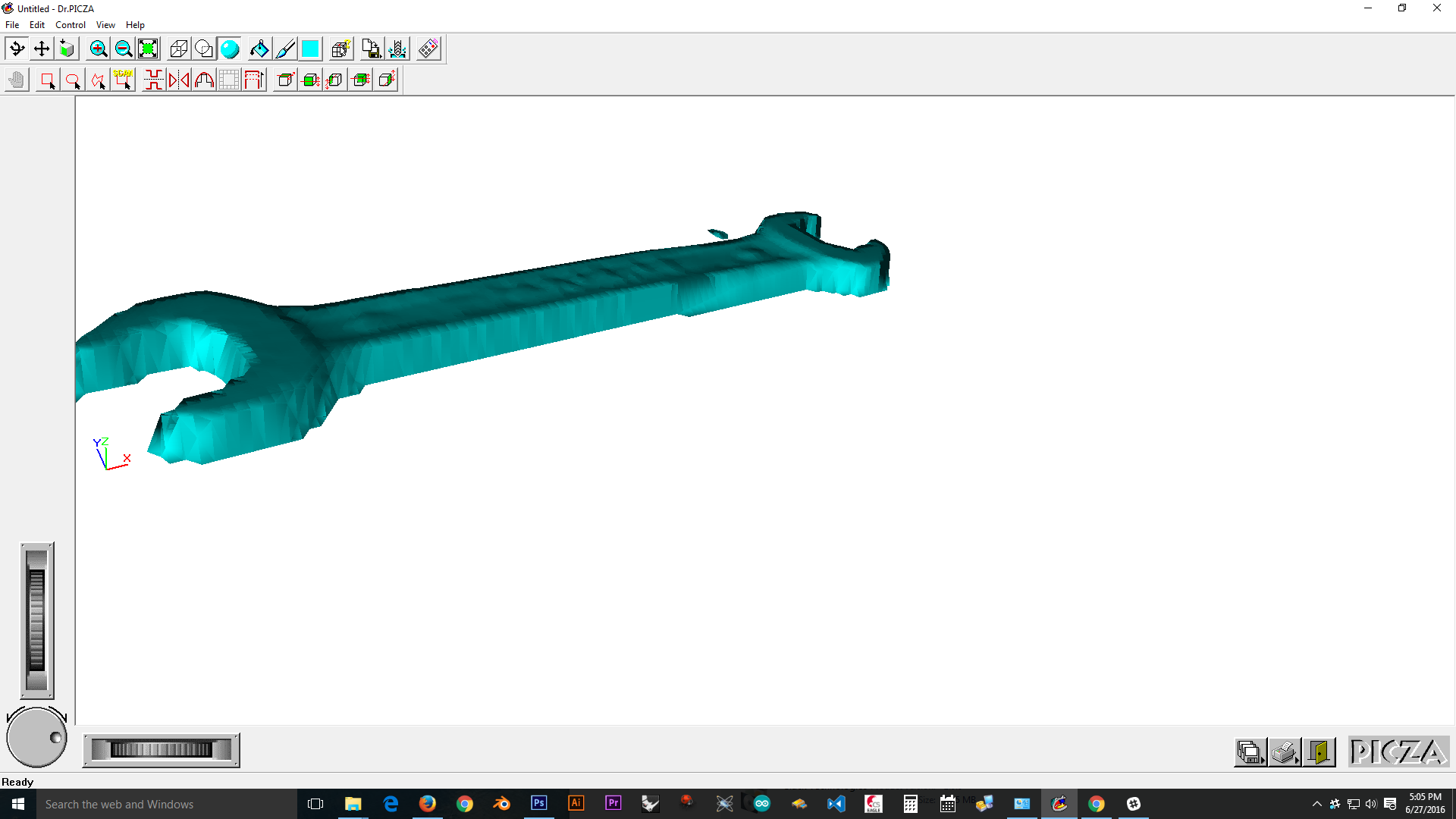
Download the stl file here