The glue is for reinforcement, we ran out of smd header pins and had to rely on the locally available straight pins. These were soldered in an angle, reinforcing with glue would help it mechanically.
Two kinds- push button and toggle.
Bounce and debounce
When using mechanical swicth, due to the vibrations between the contacting surfaces the signal toggles with high frequency for a while before settling to the state.
To debounce we add a capacitor after the switch to filter out these noises. We can also do this in software by asking the device to wait before it take another input after it detects the first input.
I used the code from the Make: AVR Progrmaming to verify the bounce and added a capacitor in parallel to switch and verified the improvement.
/*
Demonstrates using state to detect button presses
*/
// ------- Preamble -------- //
#include <avr/io.h>
#include "pinDefines.h"
int main(void) {
// -------- Inits --------- //
uint8_t buttonWasPressed;
BUTTON_PORT |= (1 << BUTTON);
LED_DDR = (1 << LED0);
/* state */
/* enable the pullup on the button */
/* set up LED for output */
// ------ Event loop ------ //
while (1) {
if (bit_is_clear(BUTTON_PIN, BUTTON)) {
/* button is pressed now
if (buttonWasPressed == 0) {
/* but wasn't last time through
LED_PORT ^= (1 << LED0);
/* do whatever
buttonWasPressed = 1;
/* update the state
}
}
else {
/* button is not pressed now
buttonWasPressed = 0;
/* update the state
}
}
/* End event loop
return (0);
}
This is a code from the book to for toogle action for the LED. You will notice that sometimes the toggle would not perform properly and you will be left with the same sate of the LED even when you pressed the push button. This shows the unreliable nature of the mechanical switches.
When I added a capacitor in paralel to the switch the performance was much better with no glitches. The capacitor managed to filter the noisy signals from the mechanical vibrations.
Switch Bounce
Debounced with addition of Capacitor
>
To start with analog input I used the hello ftdi board that I modified and had addded a button and an led. I wanted to see if I could get an analog signal from the switch and try to build a logic around it and get the led to work from the input. Instead of a variety of signal a switch would only give two signal levels.
Steps
1. Read ADC input. I used arduino sample code and c program from neil.
2. Build a suitable logic to control the LED. We are going to read only two states here, even though reading a range of states should be possible.
3. Upload and verfify if it works.
I chose c programming to begin with.
I went through the datasheet and found the following details to figure out how to use ADC in attiny.
Registers
[ADMUX] [ADCSR] [ADCL/ADCH]
Important function of each Registers
ADMUX – ADC Multiplexer Selection Register - to set the a reference voltage and input pin.
ADCSRA – ADC Control and Status Register A - enabling ADC, and prescaling.
ADCL/ADCH- the value read after the conversion is done.
To get the reading the program logic should include, starting the ADC conversion(setting ADSC of ADCSRA ), waiting to complete the conversion(reading from ADSC from ADCSRA until it goes low) and reading the data (read from ADCH and ADCL).
I also pull up the input pin. After getting the reading the logic goes something like if I receive max voltage then switch on if I receive anything less than that switch off.
Common pitfalls
I tried to tune a code copied from an online source that did exactly this. I had to do the modification to suit my situation in initialisations etc but the logic was left untouched. I initialised the ADC to use pin A7 as input, editing Neil’s initialisation code from hello.temp.45.c. But it didnt work as expected.
The LED stayed on and dimmed no matter what the input from the button. The problem was that the other program assumed 10-bit ADC conversion, hence it was checking for half of the range- half voltage being reached as an evaluating criteria for switching ON the LED. Above it the led should go on and below it the led should remain off. But Neil specifies to use an 8-bit conversion rather than a the default 10 bit in his initialisation code. The following line is what you specify to switch from default 10bit to 8 bit.
(0 << ADLAR) // right adjustThis I figured out much later while I was having a conversation on ADC with my remote guru Francisco. When I modified the logic and used the number 127 - half the reading of 254 the 8 bit max value, the program worked as it should.
Serial communication
Much before I figured out what the problem was I was trying to debug this I tried using serial communication code from hello.ftdi.44.echo.c and hello.temp.45.c and tried to get through serial communication, what the readings from the board using ftdi cable. Here also I faced some trouble and I switched to arduino further investigation.
Analog read using Arduino
All I had to do was set the arduino to use usbtiny as programmer and board and the crystal settings like here.
I found That the arduino code for serial communication doesnt work right off the bat for attiny . The following edits are required to be added.
#include <SoftwareSerial.h>
 const byte rxPin = 0;
 const byte txPin= 1;
 SoftwareSerial mySerial =  SoftwareSerial(rxPin, txPin);
And then relace all ‘Serial’ command with the variable mySerial
void setup() {
  // initialize serial communications at 9600 bps:
  //Serial.begin(9600);
   pinMode(rxPin, INPUT);
  pinMode(txPin, OUTPUT);
    digitalWrite(7,HIGH);
    mySerial.begin(9600);
    }
The program worked and there was no problms with serial communication as seen by the arduino serial monitor. However there are certain observation I made.
Observations
The program took 90% of program memory.
There was a delay in program execution from switching on the button to LED brightening up.
The minimum value was ADC read was 18( when switch is pushed it gives low to input, normally it is high meaning normally the led is on) and not zero, so the LED doesn’t switch off. You have to keep the switch pressed for it to go low.
When powered from ISP the program logic doesnt get implemented and the LED remains ON no matter what the switch state is.
After checking that I was actually receiving he serial communication using arduino, I tried debugging further in C. I told francisco about this issue and he knew what was the issue immediately. It was the baudrate. The baudrate in Neil’s code for serial communication in hello.ftdi uses baudrate setting of 115200. The code is as following
#define bit_delay_time 8.5 // bit delay for 115200 with overheadYou can change this line to
#define bit_delay_time 102 // bit delay for 9600 with overheador change the baudrate in arduino serial monitor to 115200.
The helloftdi code which I burned on the board worked fine but the code which was supposed to send the recorded adc value still didnt work. I changed the c code to use bit delay time of 102 for baudrte 9600 also, but it still wouldnt work, outputting some invisible characters to the serial monitor of arduino.
Apart from the serial communication problem everything else was working great.
Observations
Compared to the arduino code the c code compiled faster and flashed faster to the board and took much lesser space.
The biggest advantage was experienced in the speed. The speed was blazing fast as compared to arduino’s code. There was no delay experienced.
So far I have played around the ADC usage and now I am going to design and mill the board.
I chose the temperature sensor module to start with.
Download avr c code
Download Makefile
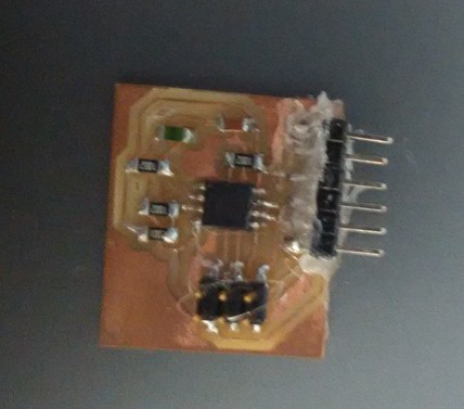
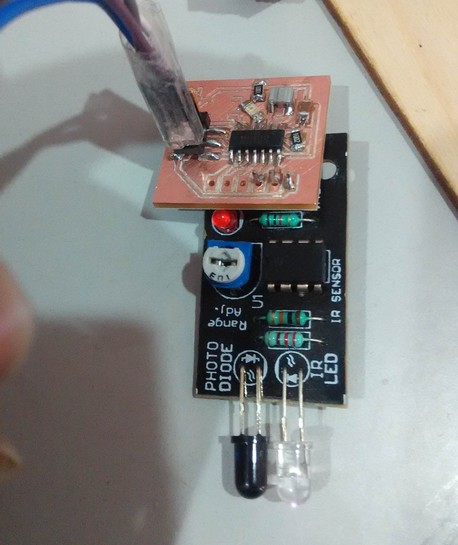
I redesigned Neil’s Temperature sensor board in eagle. Uploaded the program into it and tried to directly read the serial from it using arduino serial monitor. But it showed only gibberish. Later I used Vishnu’s input device board, and that too was giving gibberish output. When the corresponding python script was run, it seemed to respond to the sensor readin. So I tried the same temerature python script, but it read no change from the sensor. Initially I thought that this is a bug and there is some problem with the board or component. But it turned out to be a false alarm, I checked the reading again a few days later and this time it did show a different reading.
The glue is for reinforcement, we ran out of smd header pins and had to rely on the locally available straight pins. These were soldered in an angle, reinforcing with glue would help it mechanically.
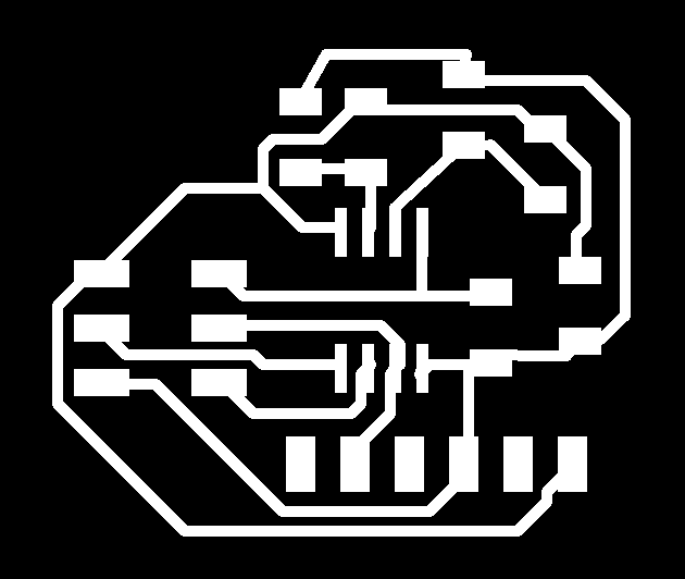
Download traces png
Download Outline png
Download Eagle Schematic
Download Eagle Board
Networked Infrared proximity sensor
Design
123D circuits was used to design the circuit. The gerber file was downloaded and using gerbv I got the png images for fabrication. This sensor is mean to be a part of a network and communication is going to happen through the serial. Al the board in the network will share the rx and tx pins and vcc and ground pins, each board will interpret the commands given in different way and behave in a different way.
Features
Bugs
Th resistor connecting the reset pin to the VCC has pads which is not compatible with 1206 resistors, You will have to orient it properly and recheck soldering.
Not sure about the footprint of the 6mm tactie switch, I had just added the provision to solder it and program it, but fir my purpose I didnt need it. Some of the traces dont get cut completely when using standard setting of fab modules modela cutting.