Networking and Communications
OverviewLast updated: 11/05/2016
Objective Design and build a wired &/or wireless network connecting at least two processors. Learning outcomes 1.Demonstrate workflows used in network design and construction; 2.Implement and interpret networking protocols; Have I... Described my design and fabrication process using words/images/screenshots? Explained the programming process/es I used? Outlined problems and how I fixed them? Included original design files and code? Summary As I had already some experience with SPI and Serial protocols, I challenged myself to learn how to set-up an I2C network. I managed to get a master (Satshakit micro) communicate with 3 slaves.Introduction I2C I2C is a syncronous wired protocol. All I know about it I found in AVR programming, chapter 17.
Master: Satshakit Micro As a master board I wanted to use a Satshakit and, since the newest version of it was just released few days back, I decided to build one. I took the Eagle schematics from the repository and I adapted it to be lasercut [1]. I managed to make an even smaller board than the original one. In addition to what said in week 4 I managed to get decent cut-through holes. In a black 1mm diameter circle I put a 7mm diameter red circle. Traces did not jump, on the contrary of what had happened previous times.
 After that I realised that I wanted to improve the way I program the board, I therefore decided to build a simple breakout in between the Satshakit micro and the FabISP. I simply drew it with Illustrator, just to be sure that I would make it exactly the same [2]. It worked out well and it is quite a convenient breakout.
//Code for the Satshakit
#include Wire.h
void setup()
{
Wire.begin(); // join i2c bus (address optional for master)
Serial.begin(9600);
}
void loop()
{
Wire.requestFrom(4, 1); // request 1 byte from slave device address 4
Wire.requestFrom(5, 1); // request 1 byte from slave device address 5
Wire.requestFrom(6, 1); // request 1 byte from slave device address 6
while(Wire.available()) // slave may send less than requested
{
int i = Wire.read(); // receive a byte as character
Serial.println(i); // print the character
}
delay(200);
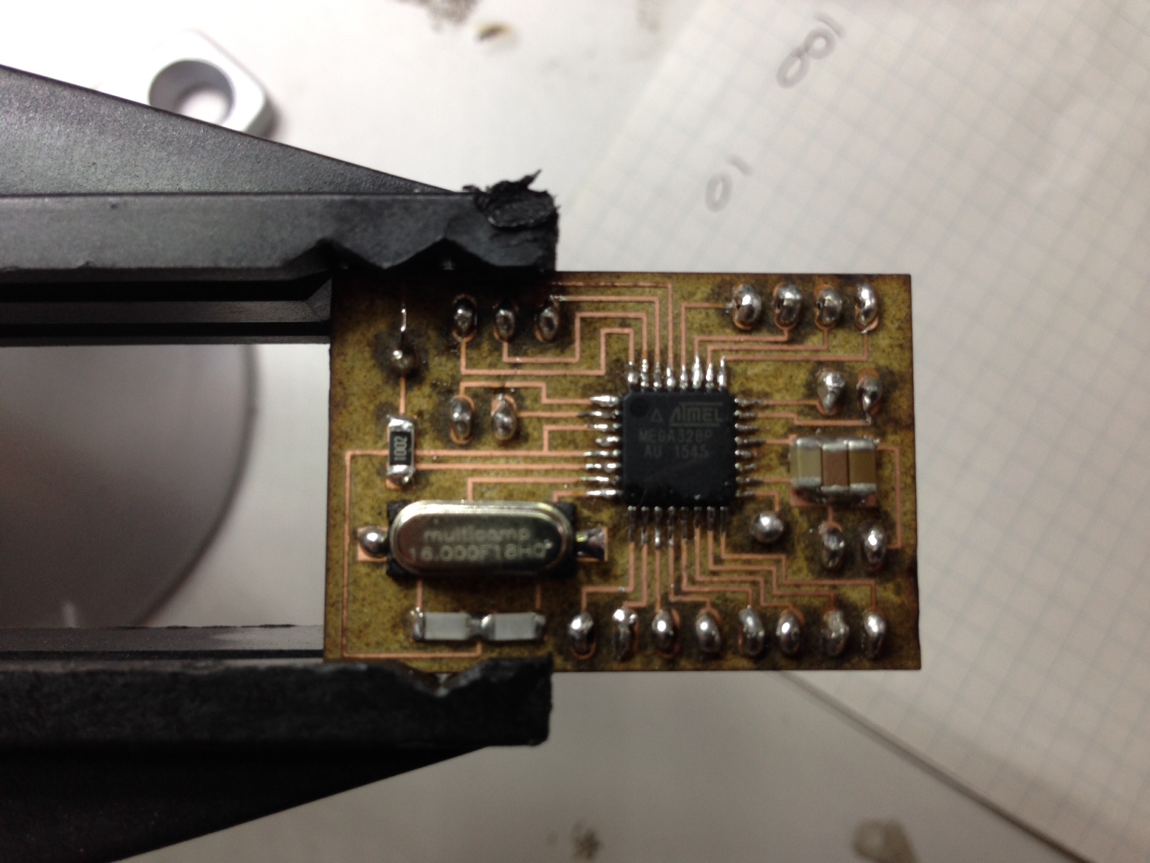
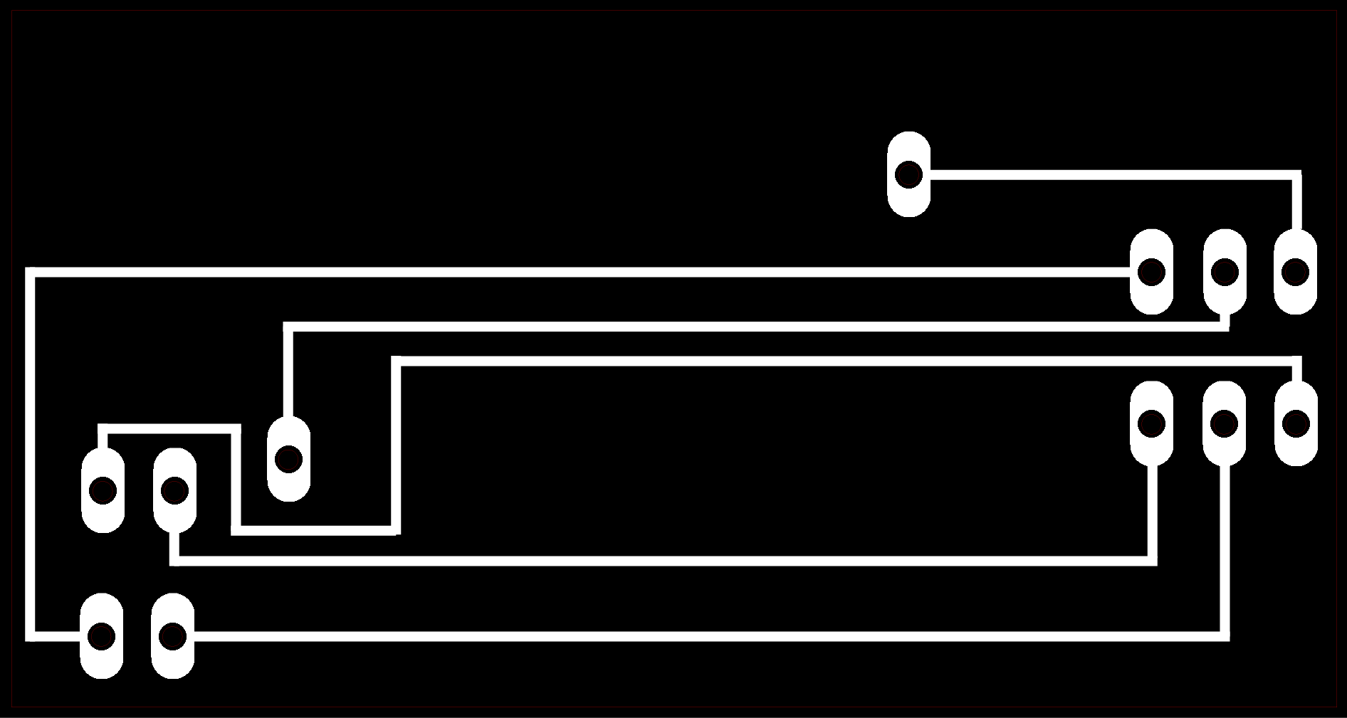
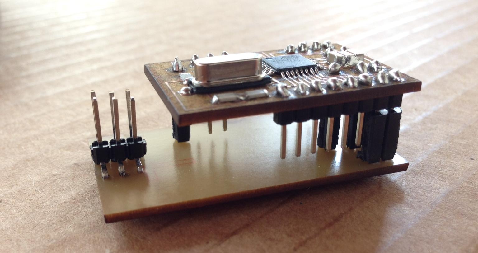
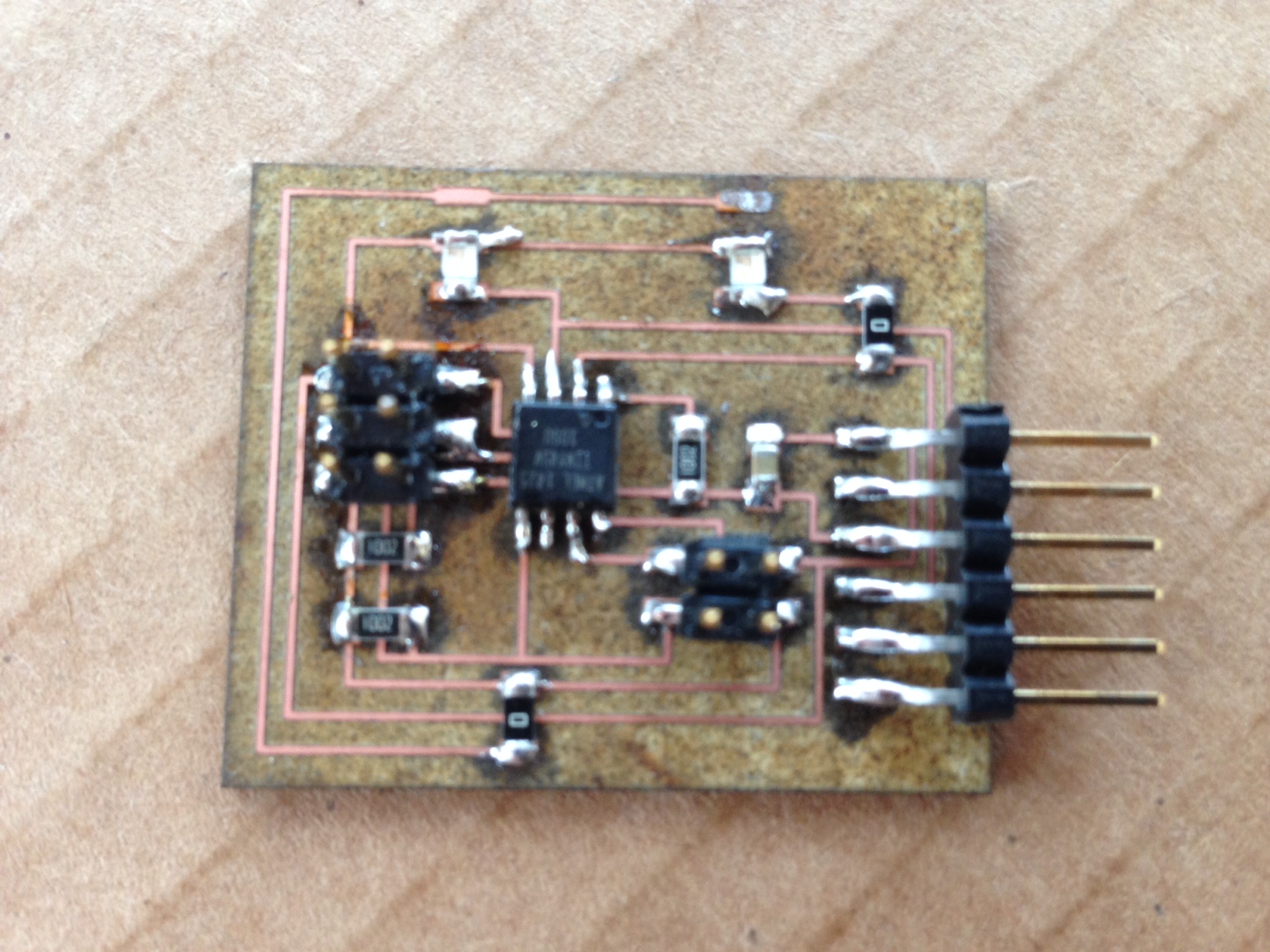
}Slave: ATTiny45 Board Together with Matteo we decided to design and build a board that could allow us for high flexibility [3]. We wanted to have all the three wired protocols on board (FTDI, SPI, I2C) and also the possibility to attach different sensors, at our convenience. The board externally supports two sensors with signal, ground and vcc.
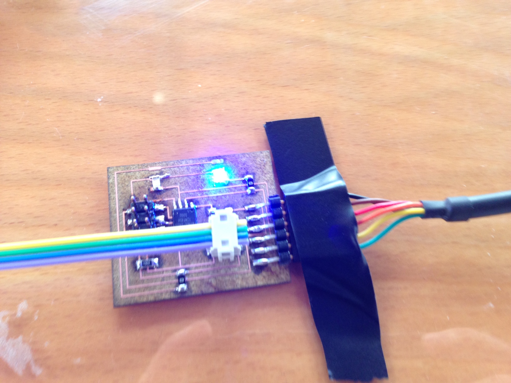
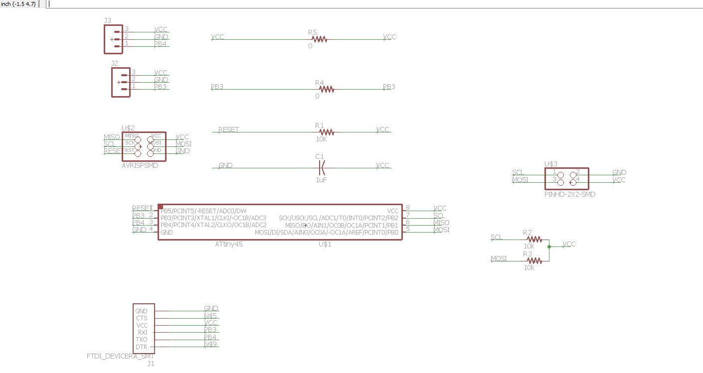 The board was lasered. The three exposed pads on top can connect to any sensor/actuator. For demonstration purpose, I put two LEDs attached to PB3 and PB4. Three of these boards were built.
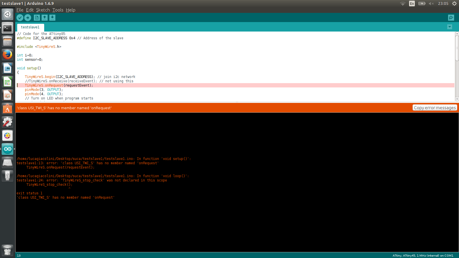
 Programming the slaves was a bit trickier than programming the master. I started to look at thistutorial but I then realised that it could not serve my case, as the ATTiny45 does not have I2C support in hardware, so it can not work with the Wire library as the Arduino or Satshakit. Another tutorial helped me heading toward the right direction. I used the library TinyWireS (there are two separate libraries, one for master and one for slave). Matteo wrote a sketch in Arduino that I slightly adapted and commented. It is below.
// Code for the ATtiny45
#define I2C_SLAVE_ADDRESS 0x4 // Address of the slave, to be modified for each
#include  //Library TinyWireS instead of Wire, because ATTIny45 does not support I2C in hardware

int i=0;

void setup()
{
    TinyWireS.begin(I2C_SLAVE_ADDRESS);
    TinyWireS.onRequest(requestEvent); //when a request is sent from the master, the action request Event is performed
    pinMode(PB4, OUTPUT);
    pinMode(PB3, OUTPUT);
}

void loop()
{
    TinyWireS_stop_check(); //still not totally clear why, but it must be there
}

// simple sketch in which two LEDs blink on PB3 and PB4
void requestEvent()
{

    digitalWrite(PB3, HIGH);
    digitalWrite(PB4, LOW);
    delay(500);
    digitalWrite(PB3, LOW);
    digitalWrite(PB4, HIGH);
    delay(500);
    digitalWrite(PB3, HIGH);
    digitalWrite(PB4, LOW);
    delay(500);
    digitalWrite(PB3, LOW);
    digitalWrite(PB4, HIGH);
    delay(500);
    digitalWrite(PB4, LOW);
    TinyWireS.send(i);
    i++;https://learn.adafruit.com/usbtinyisp/drivers
}  I did try everything. I downloaded different versions of Arduino, I reinstalled the library countless times, but still I kept on getting the same error. After some frustration I moved to Windows. I downloaded the drivers for the usbtiny here. This time Sketch-->Upload using a programmer went smooth.
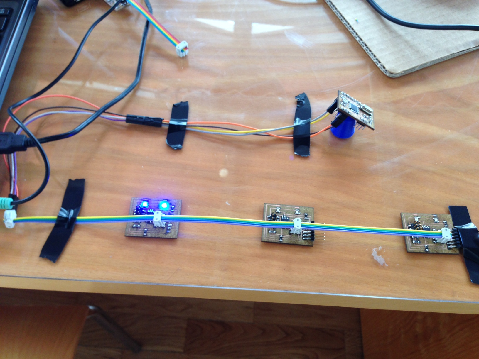
Networking In the network the master and the three slave nodes share SDA, SCL, ground and voltage. In order to power the network I then used an FTDI cable, as shown on the picture on the right.
Conclusions This week was overall successful, especially because I could really show integration with previous assignments. For the first time I learned the differences in between the wired most used protocols, and I now feel confident in making proper choices when prototyping. My only regret is that I did not get to try any of the wireless protocols.