Input Devices
Overview
Last updated: 12/05/2016
Objective Measure something: add a sensor to a microcontroller board that you have designed and read it.Learning outcomes 1.Demonstrate workflows used in circuit board design and fabrication; 2.Implement and interpret programming protocols; Have I... Described my design and fabrication process using words/images/screenshots? Explained the programming process/es I used and how the microcontroller datasheet helped me? Explained problems and how I fixed them? Included original design files and code? Summary This week I tried to get an understanding of the differences in between digital and analog sensors and the use of converters. I started with designing a mini Arduino-like board where I attached two sensors: a capacitive sensor, a push button and a flex sensor. I then designed two simple interfaces in Processing to visualize the results. Eventually I also build a stand alone board.
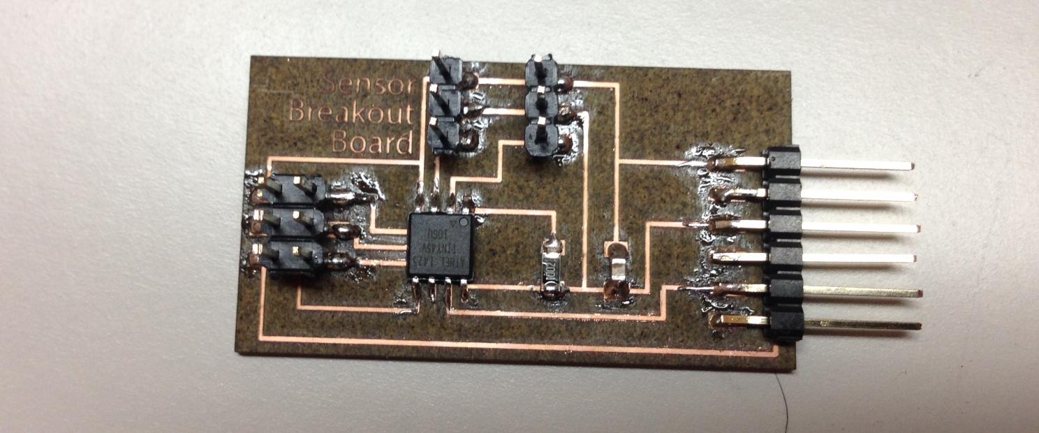
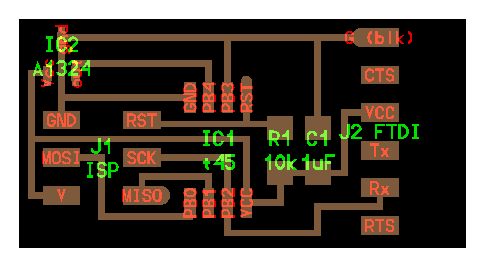
Sensor Board Since we were invited to build as many sensor boards as possible, I decided to build a board that could be attached to multiple different sensors. Eventually, I ended up building a small arduino, that contains an ATTiny45 microcontroller, the connection FTDI for communicating with a serial terminal and a connection ISP to program it.
| Amount | Component | Schematic | RS-code |
|---|---|---|---|
| 1 | ATTiny45 | IC1 | 696-2478 |
| 1 | 10K Ohm | R1 | 223-2394 |
| 1 | 1 microF | C1 | 766-1062 |
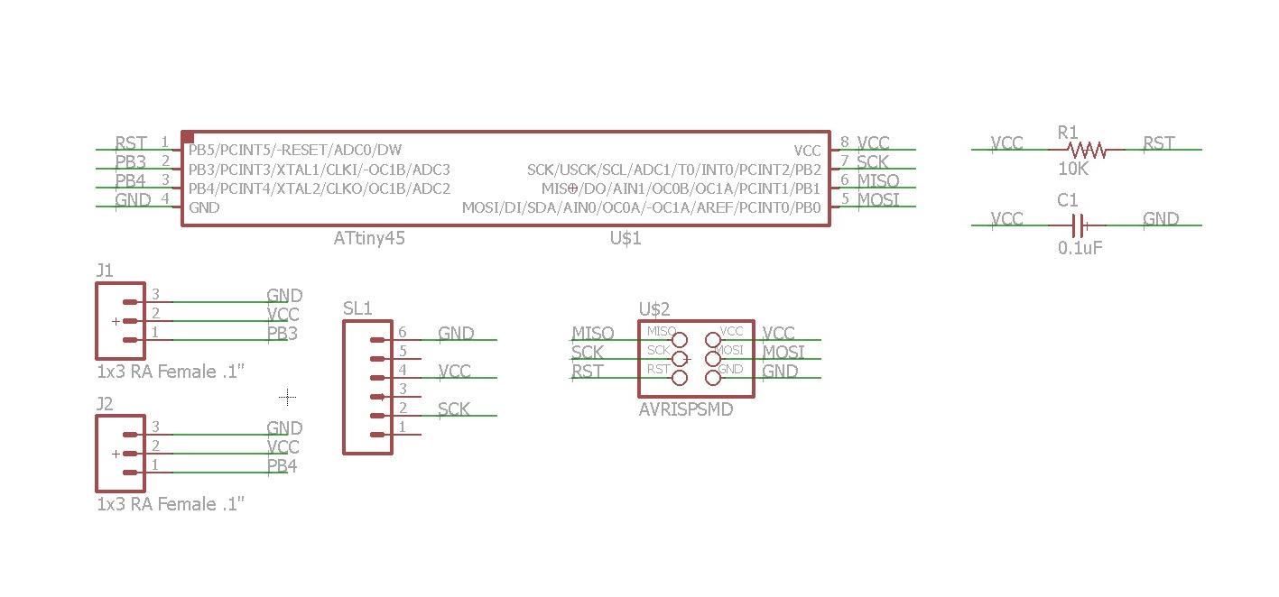
 The board was manufactured with the lasercutter, where settings are explained in week 4 [1].
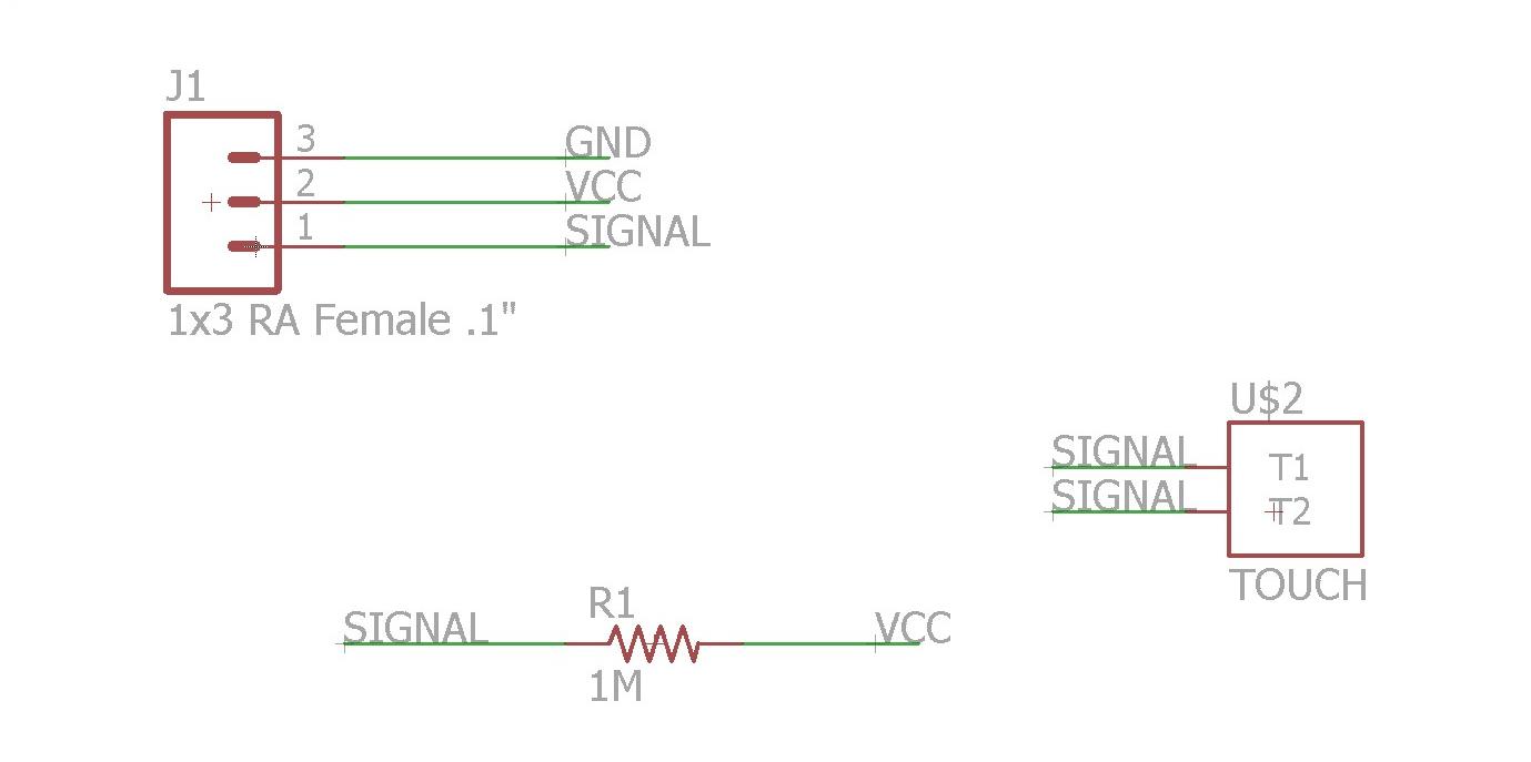
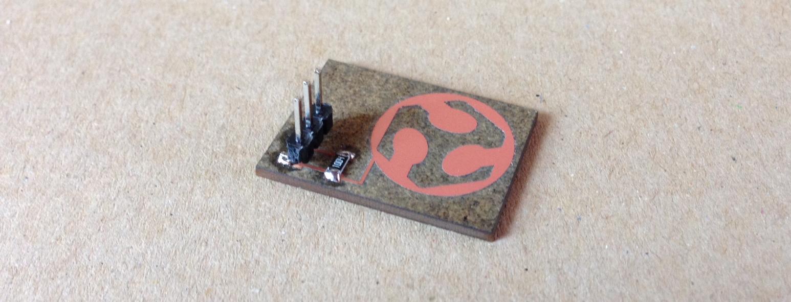
Cap Sensing As a first exercise I built an analog sensor: a one-pad capacitive sensor. I looked here for inspiration and then I scaled the project down. Eventually I built a small pad with the logo of FabLab and a 1Mohm resistor in between signal and ground [2].
 In programming the board, I started with the .c code written by Neil, I tried to interpret it as I only wanted to send one value and not a string.
In order to visualize the values I decided to write my own sketch in Processing. As I had never used Processing on Ubuntu before, I did download the package and saved it on the desktop, as I could not find it through the apt-get. Following these suggestions I launched the following commands from terminal:
In programming the board, I started with the .c code written by Neil, I tried to interpret it as I only wanted to send one value and not a string.
In order to visualize the values I decided to write my own sketch in Processing. As I had never used Processing on Ubuntu before, I did download the package and saved it on the desktop, as I could not find it through the apt-get. Following these suggestions I launched the following commands from terminal:
cd /directory
tar -xf processing-version.tgz
cd processing-version
./processing
  import processing.serial.*;

  Serial myPort;  // The serial port

  void setup() {
    // List all the available serial ports
    printArray(Serial.list());
    // Open the port you are using at the rate you want:
    myPort = new Serial(this, "/dev/ttyUSB0", 9600);
    size(1000, 600);
  noStroke();
  }

  void draw() {
    background(220);
    while (myPort.available() > 0) {
      int inByte = myPort.read();
      println(inByte);

      for (int y = 0; y < 16; y = y+1) {

        for(int z =0; z < 10; z = z+1){
            int i = inByte - 150;
      fill(10, 50 + i, i + 100);
      ellipse(y*62.5+30, z*60+30 ,50,i-50);

        }

      }

    }
    delay(30);
}Flex Sensor We had a flex sensor laying around and I simply wanted to attach it to my board. In specific, I used this. I drew a simple breakout circuit [4] and I used the same codes that I used before to read the data. I simply adjusted the scaling of the values, as the input was slightly different.
 Below is a videoclip of the basic interaction with it.
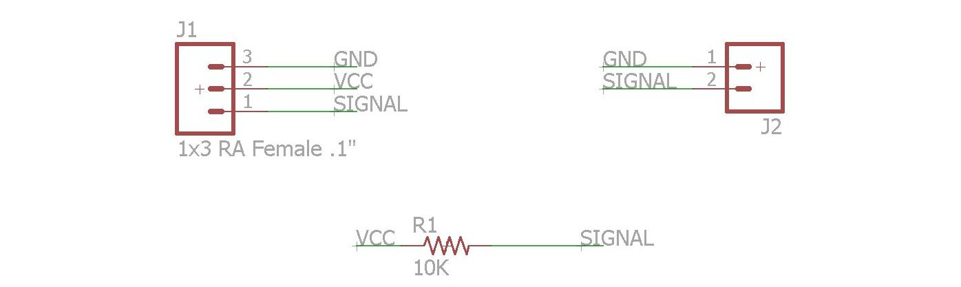
Push Button As a second exercise I made a simple push button that sends out a digital signal and I designed a simple interface in Processing to read the value. The design and production process is similar to what explained before. Below is a picture of the schematic [4].
 After the lasercut, the result is shown below. I do not have any clue, but this time the board came out pretty burned, despite the fact that I used the same settings.
 For programming, I used Neil's sketch in C, that can be found here. The only thing that I changed was the output message: 1 for being pressed, 0 for being released. I did write a simple sketch in Processing that would show the button being pressed. This time I did the conversion from char to int and I read 0-1 as input values. All the codes can be downloaded at [5]. Below is a movie of the final result.
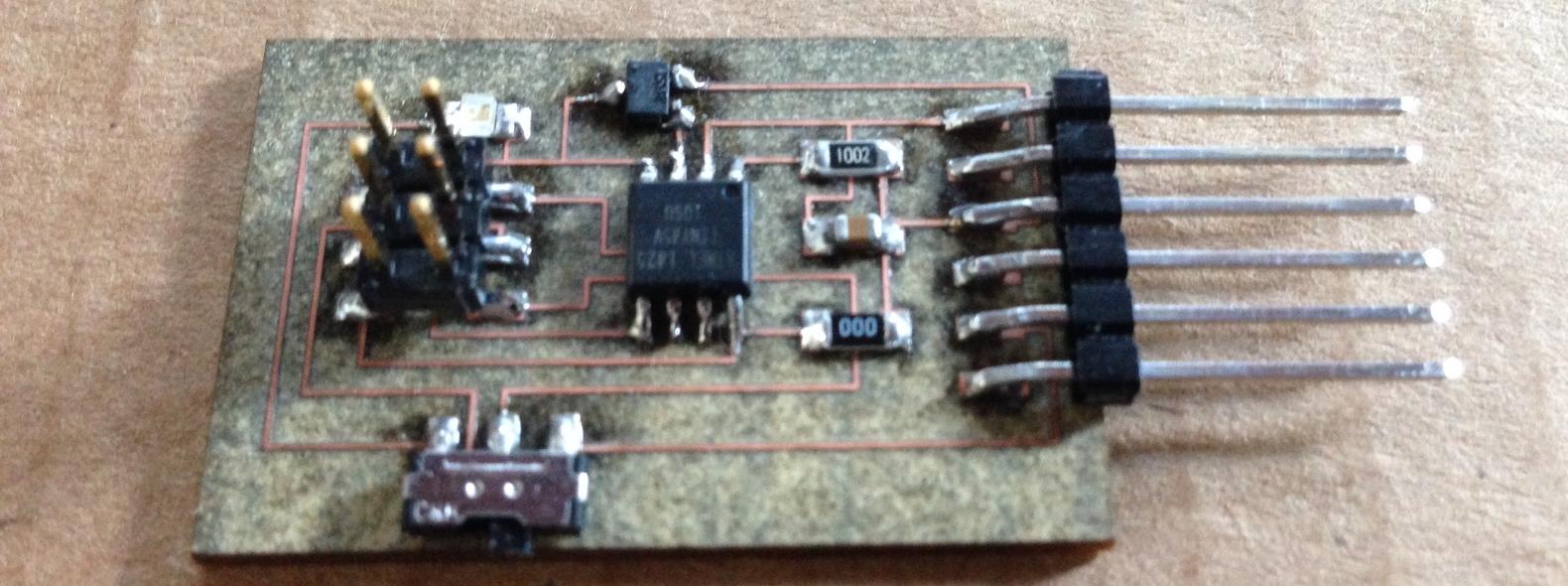
Hall Sensor Eventually I also built a full board with a hall sensor. I took this board and I added a switch to free a pin of the microcontroller. I could then put a LED output on top of it. The schematic was the following [7]:
 The board cam out quite smooth.
 When I had to program it I used Neil's sketch and I did not find the time to expand it in software as I did it with the hardware [8].
Conclusions I have a mixed feeling about the past week. To me it was a big recap of week 4, week 6 and week 8. It was not a bad thing at all, because by now I already forgot a couple of things about those processes. The fact that I did not use this week assingment to make something useful for my final, though, made me believe that I did not do anything useful.
Table of Content
Resources
- [1] Board Lasercut File
- [2] CapSense Lasercut File
- [3] CapSense Codes
- [4] Flex Sensor Lasercut File
- [5] Button Lasercut File
- [6] Button Codes
- [7] Hall Sensor Lasercut File
- [8] Hall Sensor Codes