Week 3 - Computer-Controlled Cutting
Design, make, and document a press-fit construction kit
Vinyl Cut
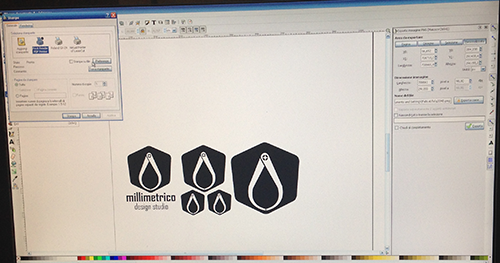
I started with something simple to get familiar with the machine. On Mac is not so easy to communicate with Roland, so I saved my vector logo in .svg in order to open it with Inkscape (I had previously drawn on Illustrator), directly on the computer matched to the machine. Then I simplified the design by reducing it into a single element.
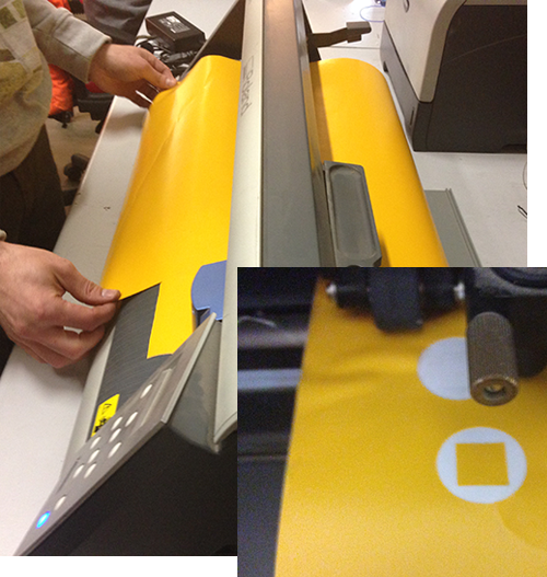
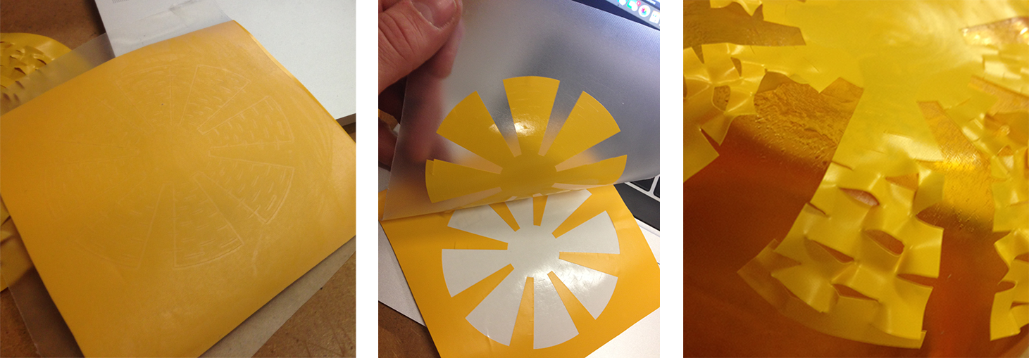
I loaded a yellow sticky film roll and I set the machine settings: type of material loaded and cutting force. Later I pressed the test button to check that the blade could cut the film without compromising the adhesive protective layer
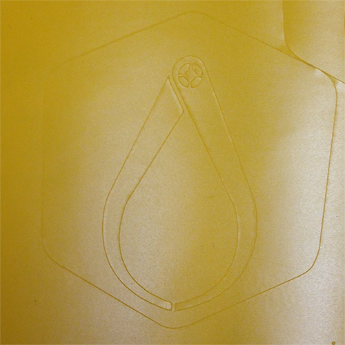
In a few seconds it appeared the millimetrico's logo! So easy that I could not believe. From that moment I fell in love with vinyl cut and I started to make an endless series of cutting tests
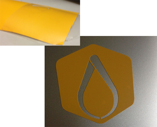
I cut it with a few centimeters of abundance from the roll and I took a transparent adhesive film with similar dimensions. Then I lifted my logo with caution with the transparent film and then I stuck it on my computer: amazing as you can see! Just a problem with the thiny elements..
Having tested the elasticity of the material, I decided to prepare new files to turn the film into a decorative pattern. The initial idea was to create a parametric design to be applied to lighting elements
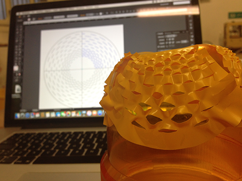
I repeated the process several times with very interesting results, unfortunately a week passes very fast, I'll keep the idea on standby for now.
Laser Cut
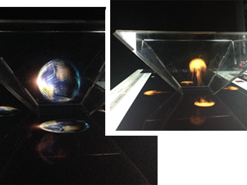
I decided to design a parametric Pyramid Hologram Screen Up. Apparently
it's not relevant to my final project, but it's a good opportunity to explore some aspects of the light refraction, which could
be useful at the end.
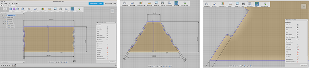
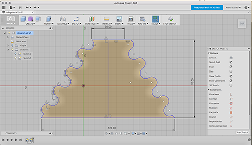
Choosing a combination of 3 parameters (lower base, higher base and height), I can change the size and
adjust my project to an infinite number of screens: I could cut a pyramid for smartphones as for a 40-inch TV. Then I added the
thickness parameter on both sides to adapt it to the thickness of every panel.
I
designed it with Fusion 360, constraining the proportions with the commands of the Sketch Palette.
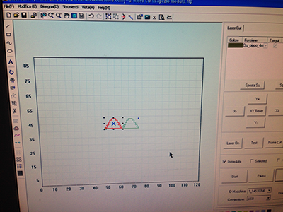
I created a .dxf file and I imported into the laser cut's software. To test the design, I chose a 3mm plywood panel. To make the final product instead I selected a 2mm plexiglass panel.
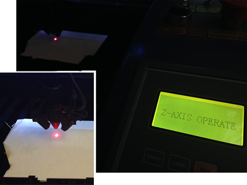
I set the focus using the LEDs pointers, moving the Z axis until the two dots produced by the pointers were overlapped.
To execute this operation on transparent plexi, I stuck a piece of paper tape in the corner and I set the Z at that point,
without forgetting the tape's thickness.
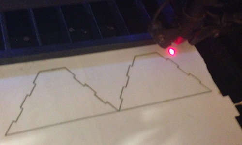
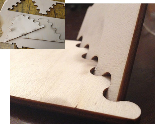
For the tests I chose to create just a cutting level, probably later I will insert an engrave level for the Fab Lab's logo . Setting speed to 40 mm/sec, power to 60% and acceleration to 300 mm/sec (150 in curve). It was a good cut and you can see it from the cutting edge, that is not carbonized.
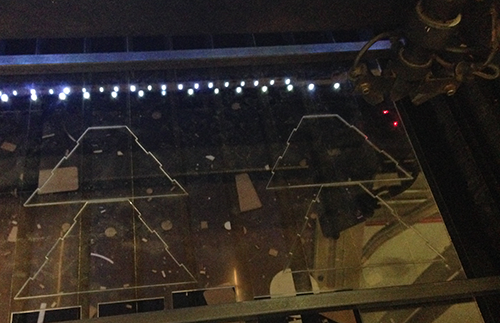
Satisfied by the cut on the plywood, I set the cut for the plexiglass. I set the speed to 60 mm/sec, power to 80% and acceleration to 500 mm/sec (250 in curve). I lowered the air pressure at 1 bar to obtain a more polished cutting.
Good result, but the particular inclination assembly, forces me to change strategy. With this kind of cut it is not exactly a press-fit construction kit: I had to use a bit of tape.
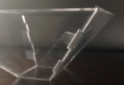
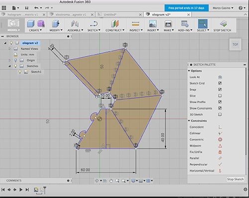
To assembling an object with no perpendicular walls, I choose a rounded solution like that. It works well and is incredibly self-supporting
I modified the design, alternating male on one side and female on the other, in order to have a single module interchangeably.
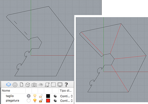
Talking to my mentor Enrico Bassi, I discovered a very special plastics processing system, called Laser Origami, that consist of bending edges putting out focus the laser. I had no time to try, but could be a very interesting solution for this kind of project.
However I import the .dxf file in Rhinoceros and I fix it with 2 different layer, ready to try it soon!
RETURN UP
| ← week 2 / Computer-aided design | week 4 / Electronics Production → |
|---|