Week 11 - Input Devices
Measure something
Steps:
* Design a board with sensors
* Program and read it
Design a board with sensors
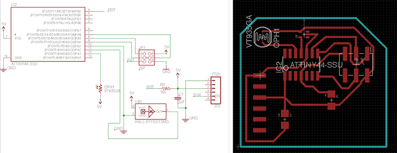
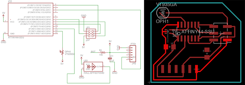
I design a board with an attiny44 and a LDR sensor (a fotoresistor) and a Hall sensor (used to read the variation of a magnetic filed).
So I design my board on Eagle.
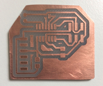
Than I mill it and I test it with the tester.
While I was doing this operation I igure out that one pin of my micocontroller was disconnected. In eagle there was the wire but disconnected, so I sold all the components and there I create a simple bridge.
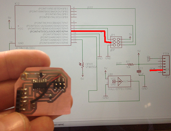
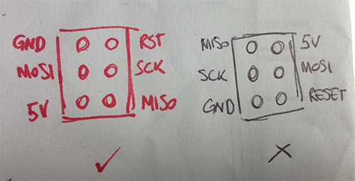
Connecting to the ISP there was trouble, so I take my time and I controll the shematic: The pin connection were totaly wrong! I change it and I design again the routes.
Program and read it
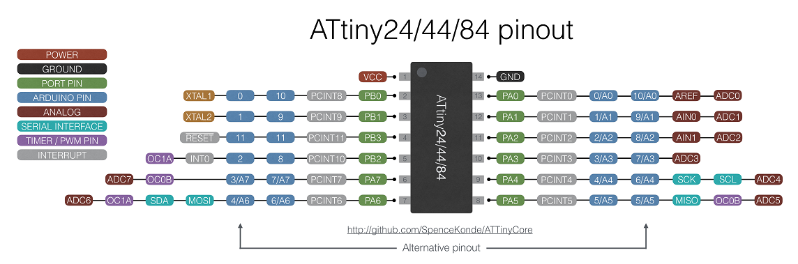
I decide to program it using the Arduino IDE, so I use this useful image from the Git Hub page of the Arduino core for ATtiny.
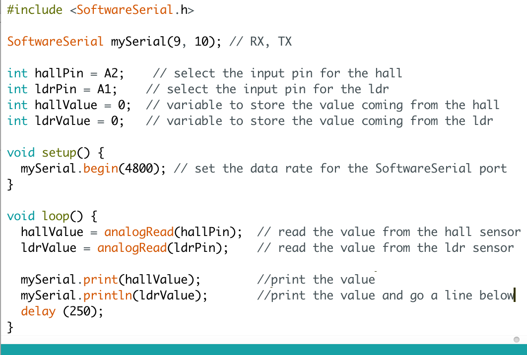
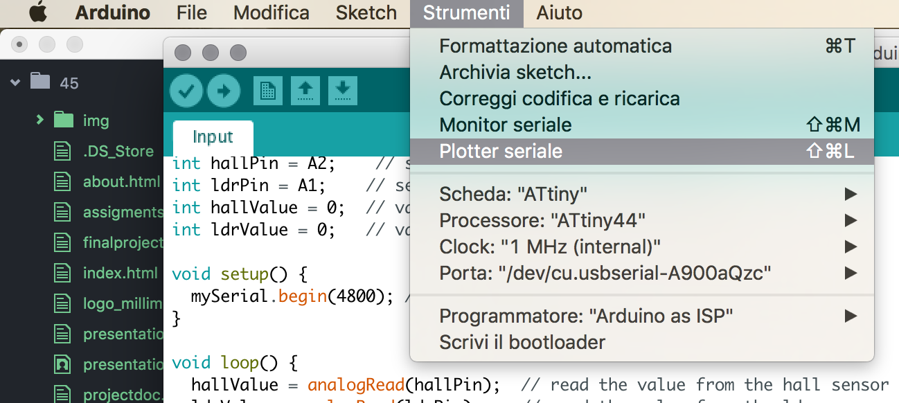
I write a simple code that check the sensors input. The ATtiny44 that I used doesn't have e real serial port for comunicate, so I create a SoftwareSerial port
I flash it into my board, using an ArduinoUNO as ISP.
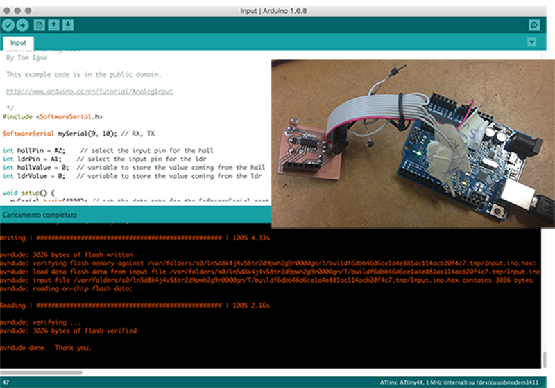
I open the serial monitor in the Arduino IDE and, as you can see in the .gif below, works!.
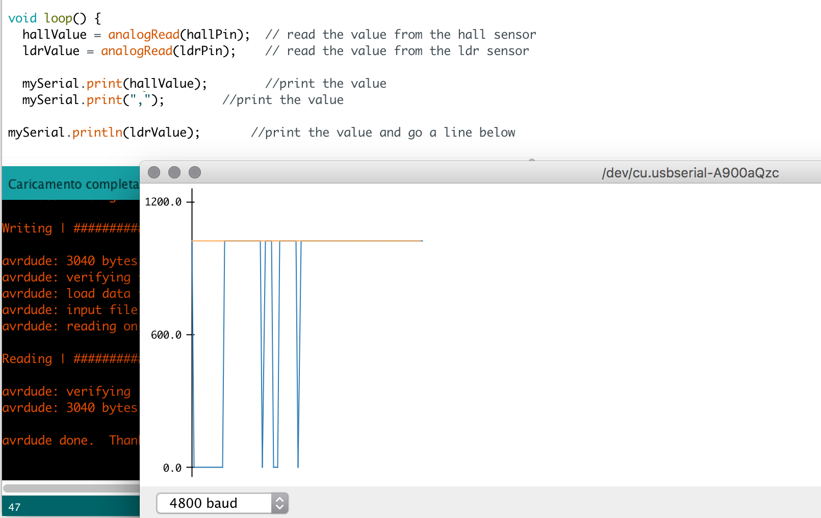
I found a super cool serial plotter on the IDE. If you use "," divide the 2 input in a interesting grafic.
RETURN UP
| ← Week 10 / Machine Design | week 12 / Molding and Casting → |
|---|