- Stefano Galbo
Beginner
Assignments
- Add a sensor to a microcontroller board and read it (week 11, input device)
- Add an output device and program it to do something (week 13, output device)
Input
These are two diffucult assignments for me, because I don't know much electronic, but I will try to produce something useful to my final project: I would activate some effects (hot, cold, air) when you touch a zone, so I thought that a photoresistor is a good solution to read hand proximity.
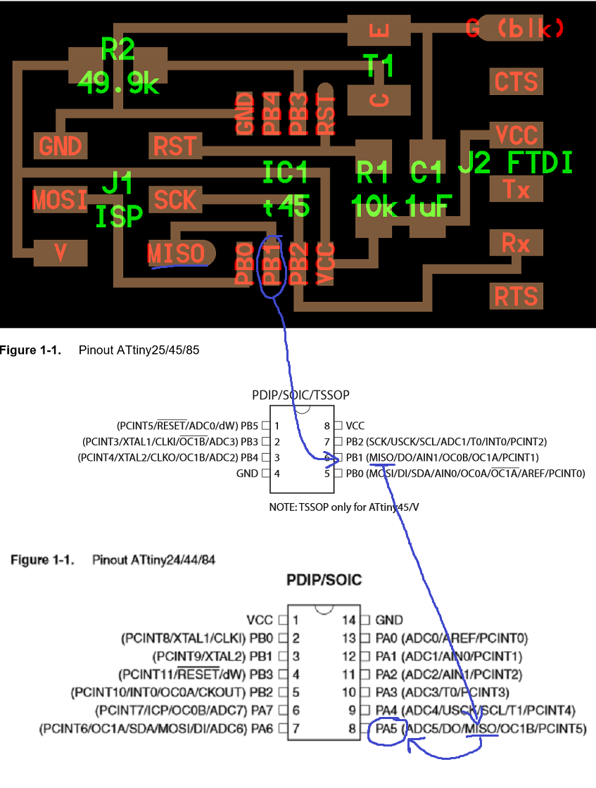
So I started from Hello.light example and I tried to copy it, but we have Attiny44 instead of Attiny45 here in FabLab Torino: I had to download the datasheets (Attiny44 , Attiny45) and compare them.
I know that the next method is not professional, but I'm a beginner in electronics so it's the only I found to make the assignment my self: I looked at an Attiny45 pin in Hello.light board, then at that Attiny45 pin in its datasheet, finally I looked for the same pin in Attiny44 datasheet.
For example, in Hello.light board PB1 goes to MISO of pin header --> PB1 in Attiny45 has (MISO) --> (MISO) is PA5 in Attiny44 --> in my board PA5 has to go to MISO of pin header!
In this way I added a photoresistor, now I have to add a little fan. I looked for a fan inside Eagles libraries..fortunately a friend told me after many minutes that I have not to find "fan" component but a generic connector...I'm a real beginner, damn!!
Update
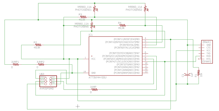
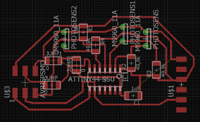
I changed idea: I will make a board just for 3 input, and then I will make another one just for output.
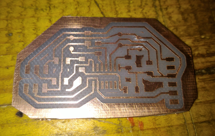
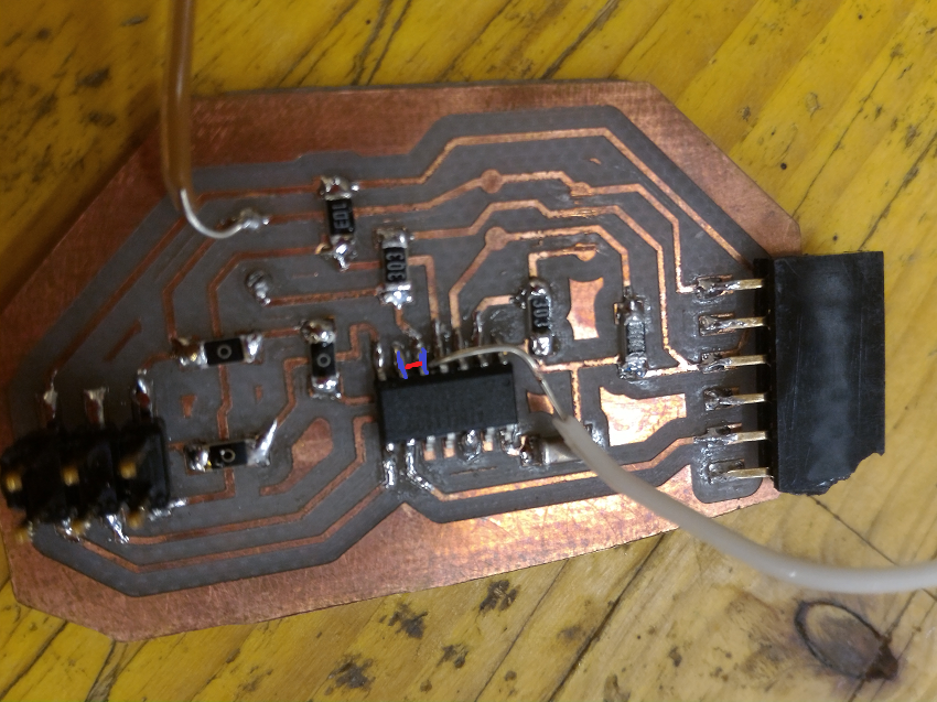
After many hours at working, this is my final scheme, his board and finally his nc file ready for milling.
Correction!
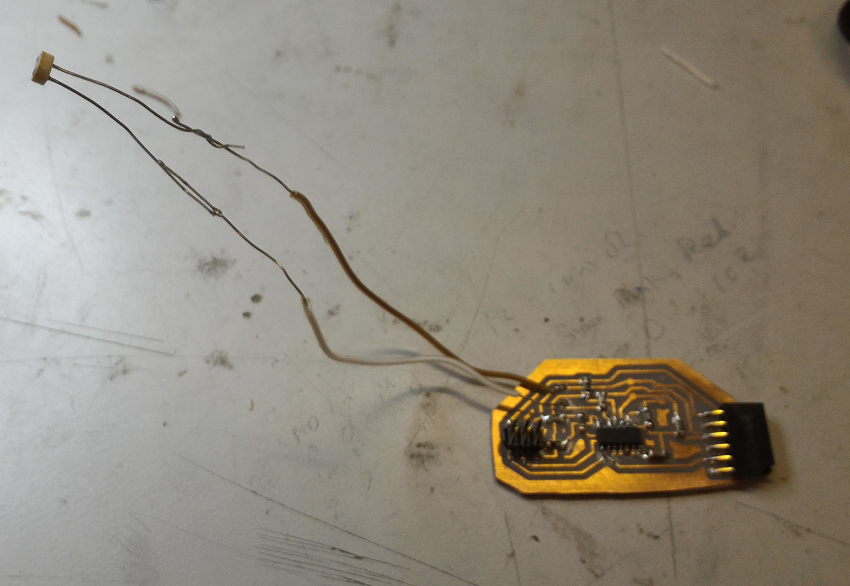
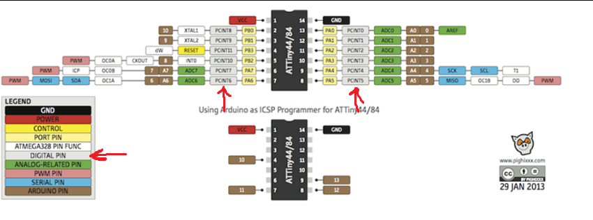
Terrible mistake: I made my board looking at Neil's example, but I forgot different pinout of microcontrollers; in particular, I connected the photoresistors to pins without analog input!
In order to save this board and begin to do some tests, I will connect pin 5 to pin 6 (which has ADC). Thanks to my classmate Gianfranco Caputo for all the help!
Programming
I decided to program my board by an Arduino Duemilanove as ISP programmer.
First I looked for how to connect them and I found this useful page.
In another section of the same page I found how to program my attiny: just following this tutorial step by step, I was able to do everything!
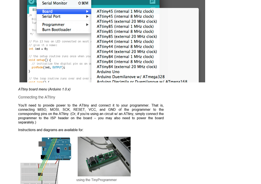
In this way, I could write a sketch in Arduino to set the actions of my Attiny.
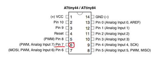
Advice 1: remember that Arduino pin-out is different from Attiny pin-out (thanks Gianfranco Caputo!): for example, I connected a photoresistor to pin 6 of Attiny, but in the sketch, Arduino will need to call this pin "pin 7"!
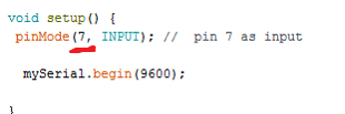
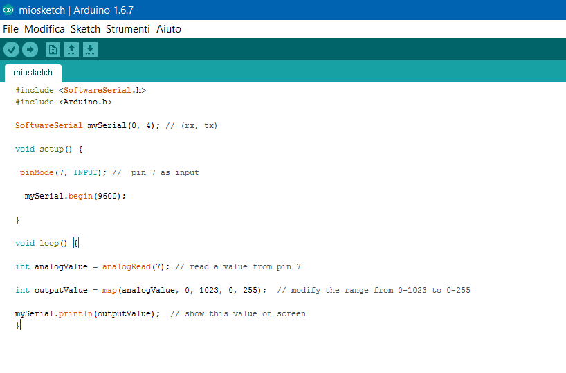
Advice 2: Attiny44 hasn't got an hardware serial port, so I need to create a virtual one. I found this example and I wrote these commands.
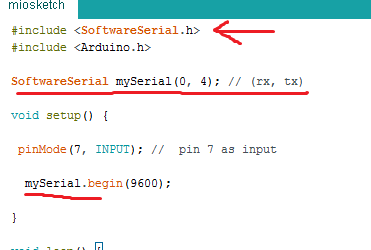
Finally I compiled the sketch, its goal is to show different values on my screen, depending on the light that hits the photoresistor: here the final sketch. The loading was successful.
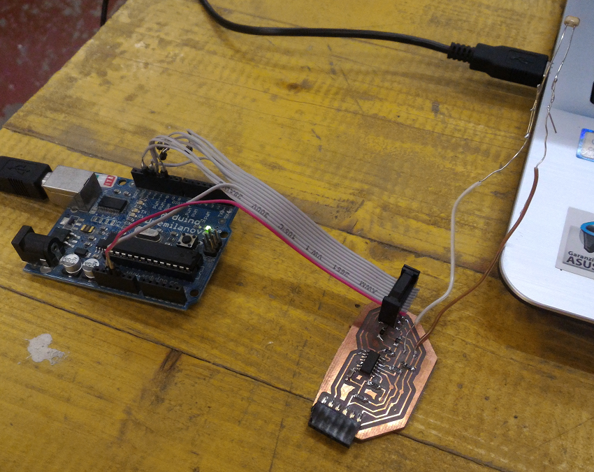
Last step: test my little board in action! I connected it with usb cable, I downloaded HTerm (just a terminal software), and I covered/ uncovered the photoresistor...this is the result:
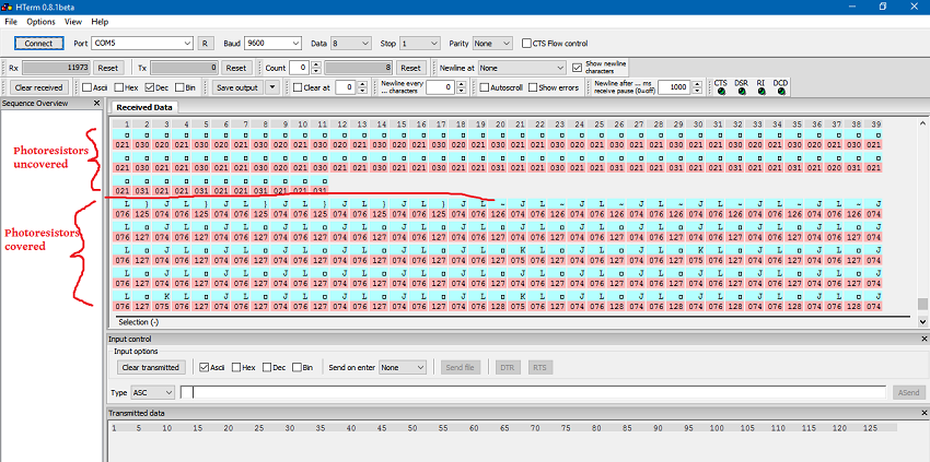
I forgot to insert a delay, so the input board sends values too quickly, however in this video you can see that the board works:
Output
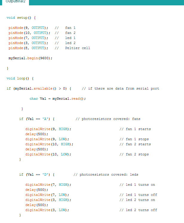
I decided to create an output board, with 2 leds, 2 fans and a Peltier cell.
With this thing in mind, I looked at week 06 (electronics desing) and added 2 leds; other outputs need just a pin header 2X1 (1 pin for vcc, 1 pin for ground). In order not to make further mistakes with pins, I looked for Attiny pinout to be sure of digital/analog outputs.
As you can see, no problems for choosing which pins have digital signal.
So I drew my board:
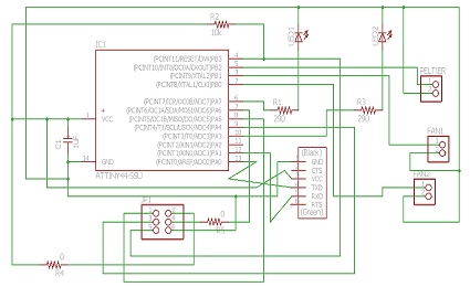
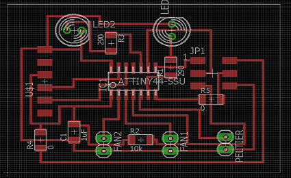
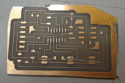
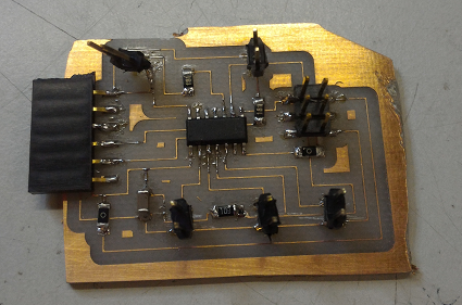
Here the scheme, the board and finally the .nc file for milling.
In order to test the output board, I loaded into it a simple sketch to turn on leds and fans depending on chars received from input board: at the moment, just remember that output board gets chars from its serial port (for details, let's go to week 15).
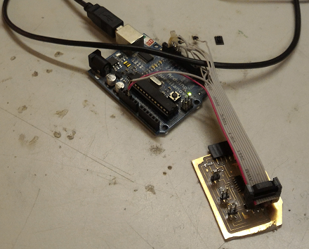
Then I connected input board and output board.
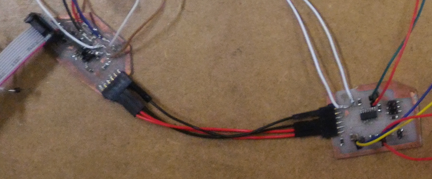
My output board works!