- Stefano Galbo
Beginner
Serial port
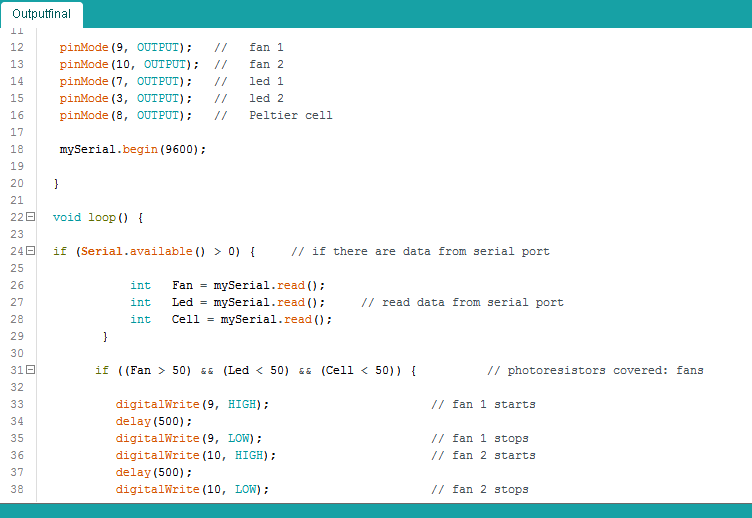
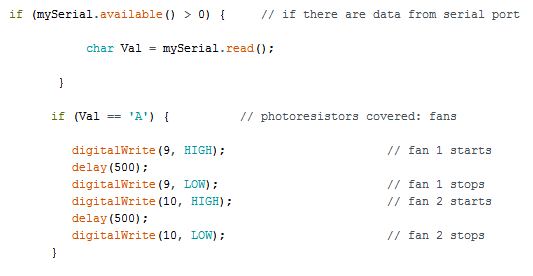
I would connect my input and output boards through the serial port, so I started to program the output board for this goal; I remembered that the input board sent 3 values from photoresistors, in particular under 50 if uncovered, over 50 if covered, so I wrote all the possible combinations of 3 values and their each actions on digital pins.
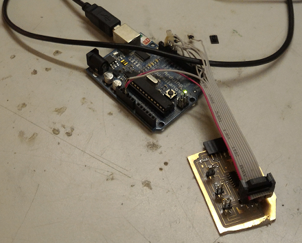
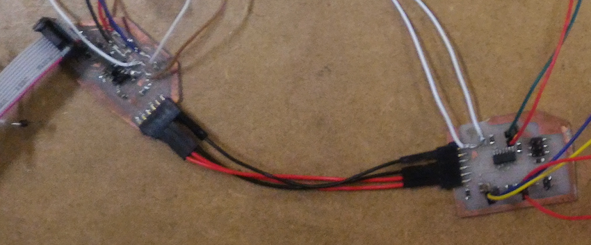
For physical connection, I decided to use wires between 2 connectors, in particular VCC 1 with VCC 2, GND 1 with GND 2 (in order to have the same "zero point"), RX 1 with TX 2 and TX 1 with RX 2: in this way, the values sent from input board didn't go at PC but directly at microcontroller in output board.
The first attempt is obviously failed: nothing happened in output board. Problems could have been many: anywhere there is a short circuit? The output board is on? Serial ports are speaking each other? The 2 loaded sketches are correct?
I had to start over to find it out!
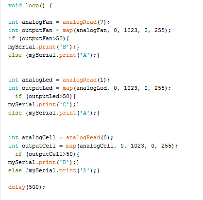
First I made a small change in input board: I thought that it could be a problem to send a numeric value with ASCII code, so I simplified and I translated numbers in chars. Then I verified with HTerm and it was working correctly.
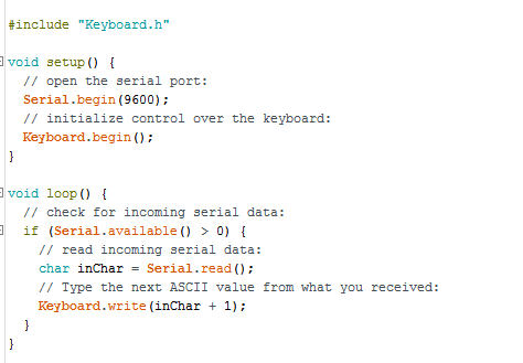
Second step was to verify the serial port of output board, so I loaded a simple example in Arduino libreries, and also the output board was working.
I loaded a new simple sketch in output board, I tried again to connect my two boards, and....they don't work...whaaaat??
I didn't know what to do...so I started to flow examples randomly and I came across one called "TwoPortReceive", I noticed a command never seen - Serial.listen() - and I added to my sketch...it's possible that it was the only problem?