week 19
Project Development
Complete your final project, tracking your progress
Documentation during development
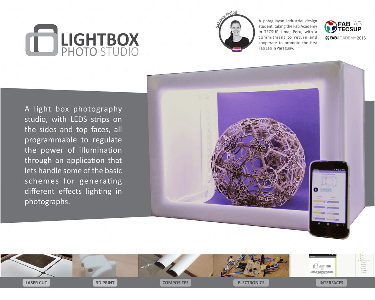
Fortunately I completed all tasks of my final project at time. what has worked best was the LED strips control through the app on cell phone. And I would like to change the material of the lightbox, the acrylic for the polypropylene plastic, to can fold in exchange for arming and decrease the weight thereof. But for lack of time and with the disadvantage of not being in my country, I did not meet local suppliers to acquire the material and try my first ideas.
I learned a lot, the importance and benefit of being able to test the designs from virtual models to rapid prototyping, programming and manage functions from the cell phone, and generate solutions with the materials and tools available. No object is completely finished, you can always improve, add features or simplify the design.
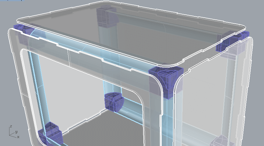
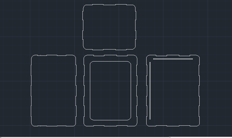
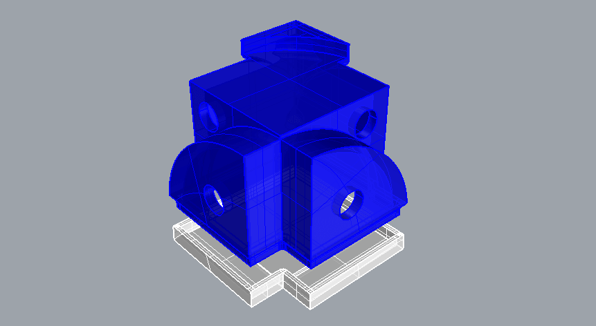
To design the lightbox i used AutoCAD for 2D drawing but for designing the cast of the LED Tracks, the cornerbacks connectors and the electronics box i used Rhinoceros. All parties joined pressure and pole socket, is fully disassembled for the saved, no screws or glue were used.
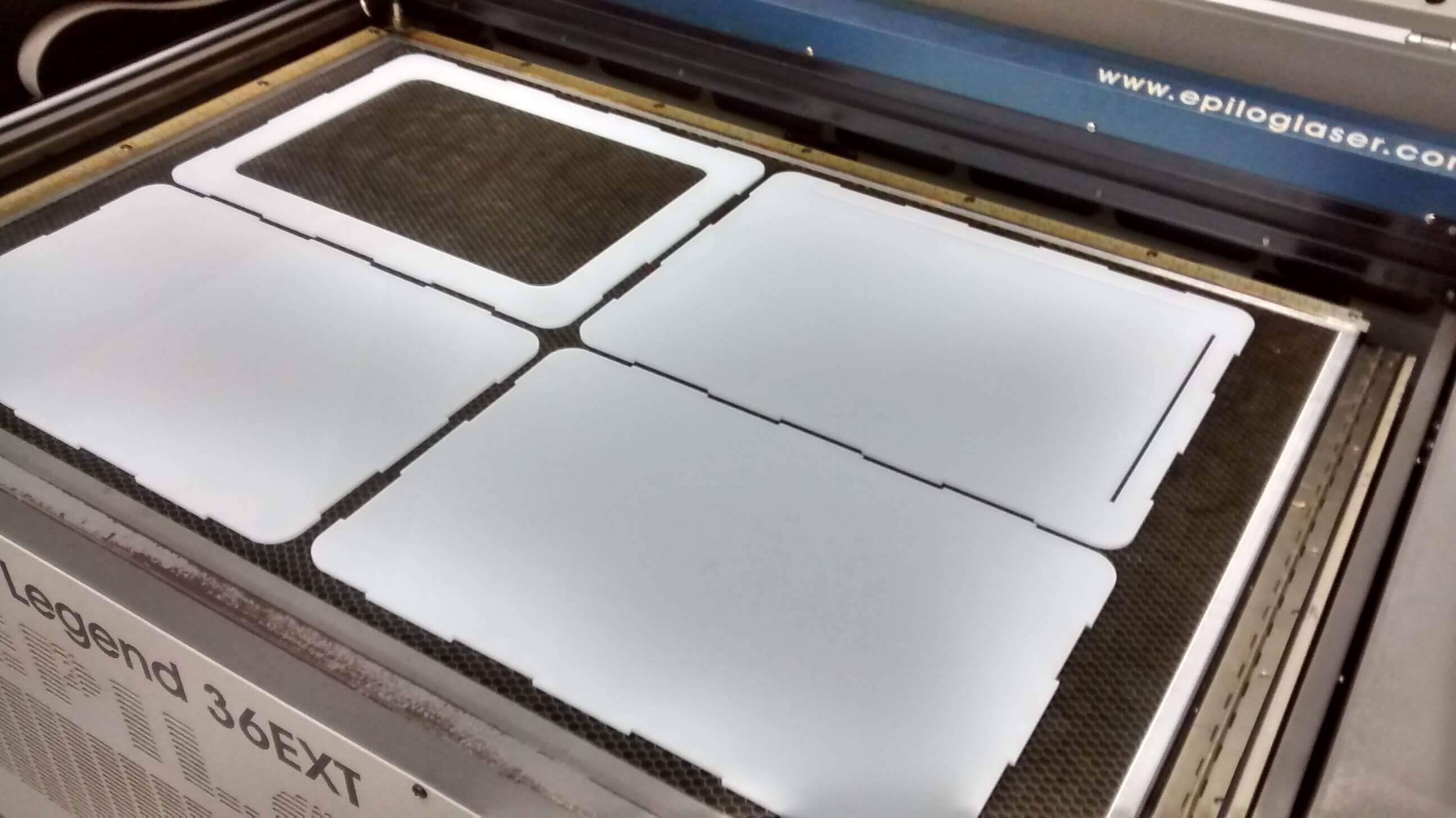
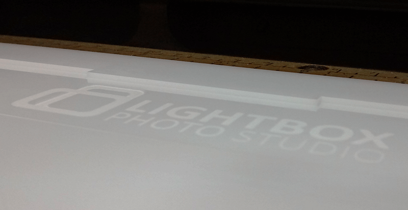
For the LIGHTBOX was used the laser cut machine, to cut and rasterize the brand in the front face.
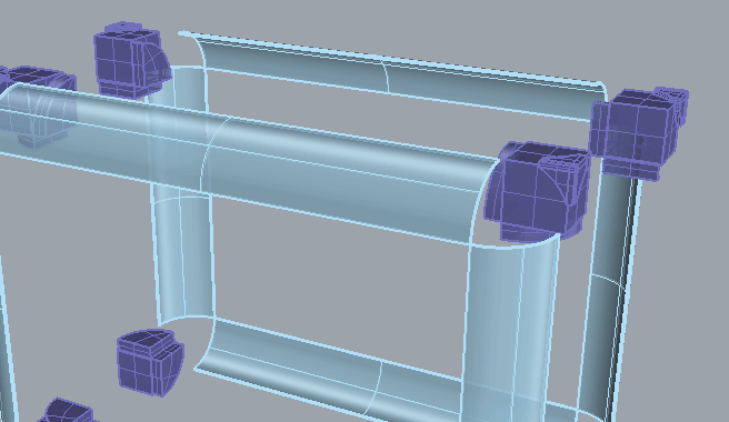
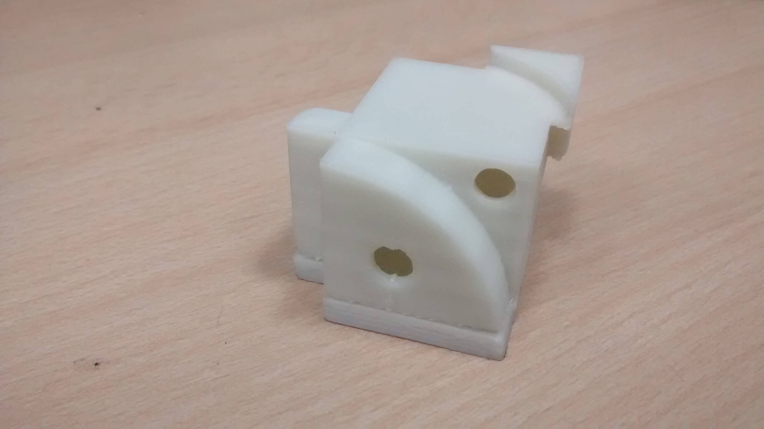
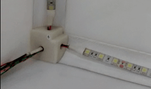
To fabricate the CORNERBACKS CONNECTORS i used the 3D printer. It will be used to cross wiring in their holes and can be connected to the electronics box. These will be located in the empty corners generated by the union of all sides of the Light Box.
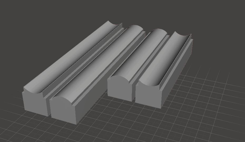
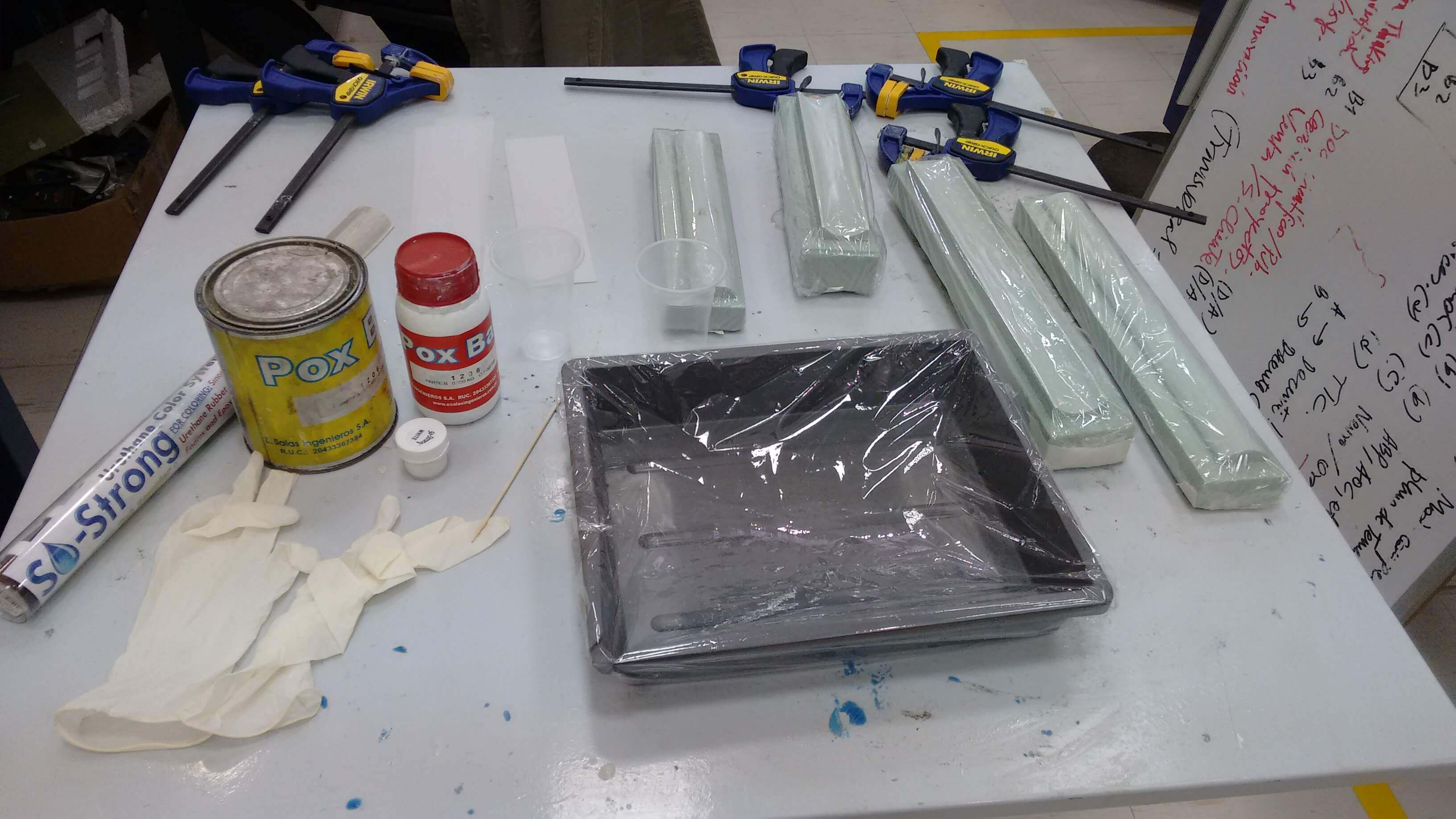
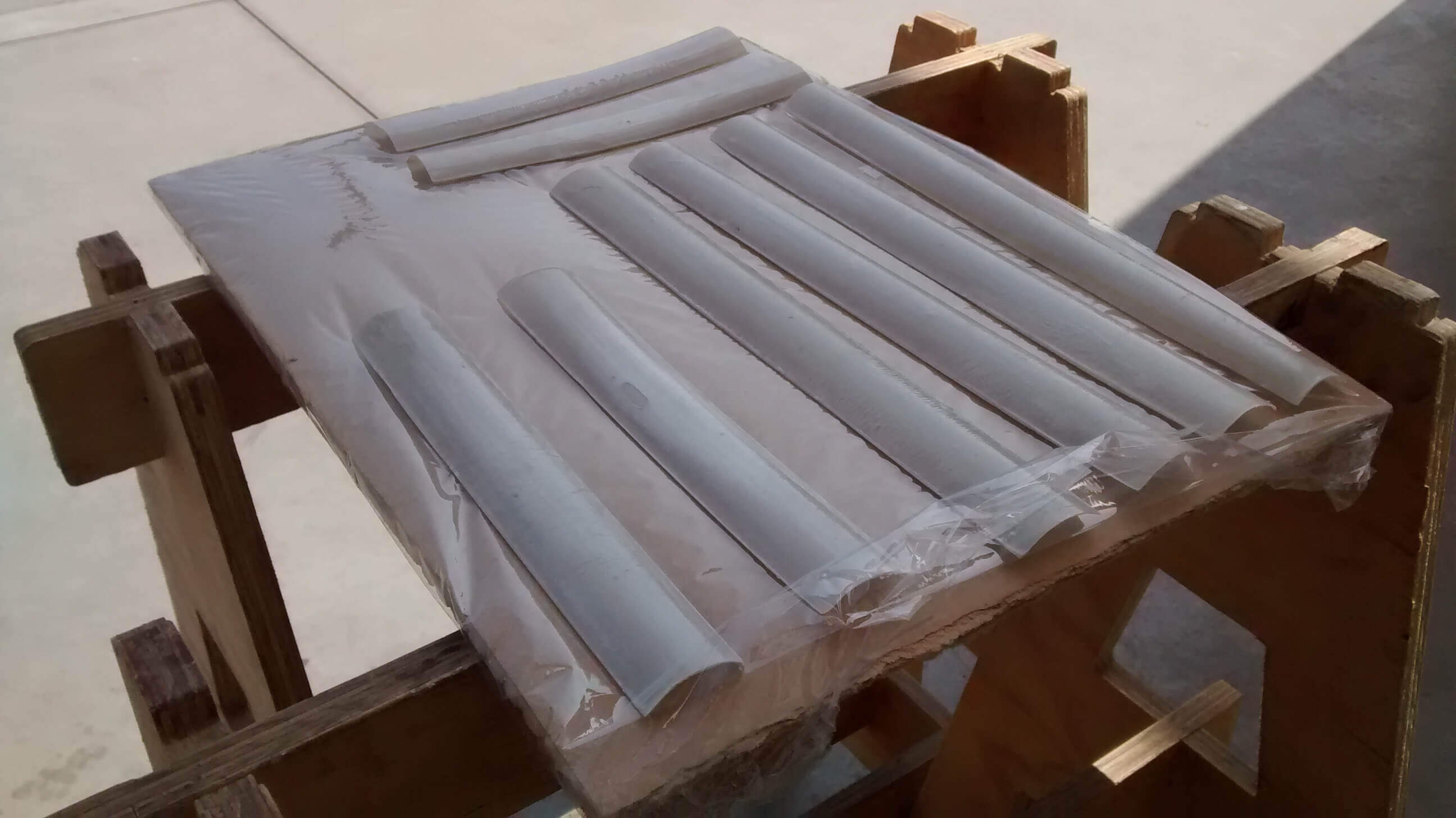
The LEDS TRACK, it's built to composites technique, the materials were vegetal paper and resin epoxy. First i designed the negative mold, then i milled it with the shopbot machine. And finally, when the object was dry i painted with white spray.
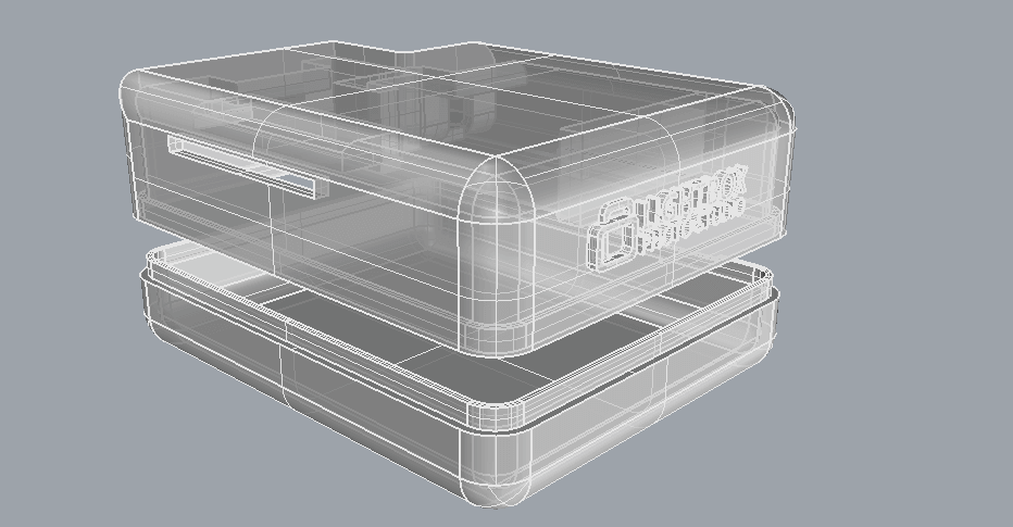
Also i designed the packaging for the electronics boards in rhino. It was printed in the makerbot.
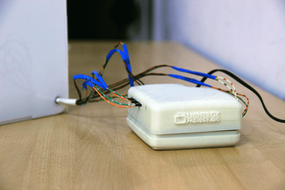
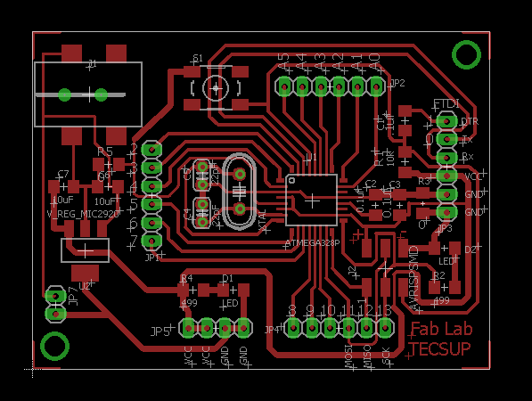
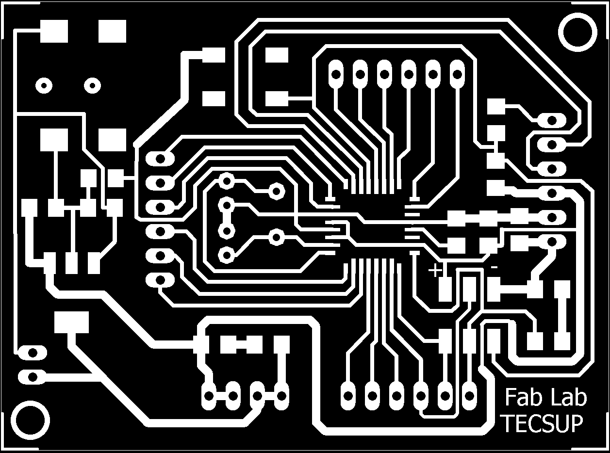
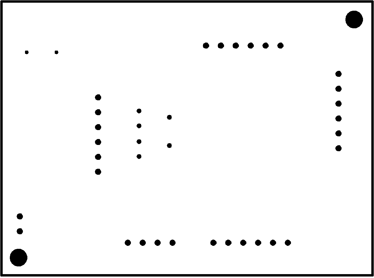
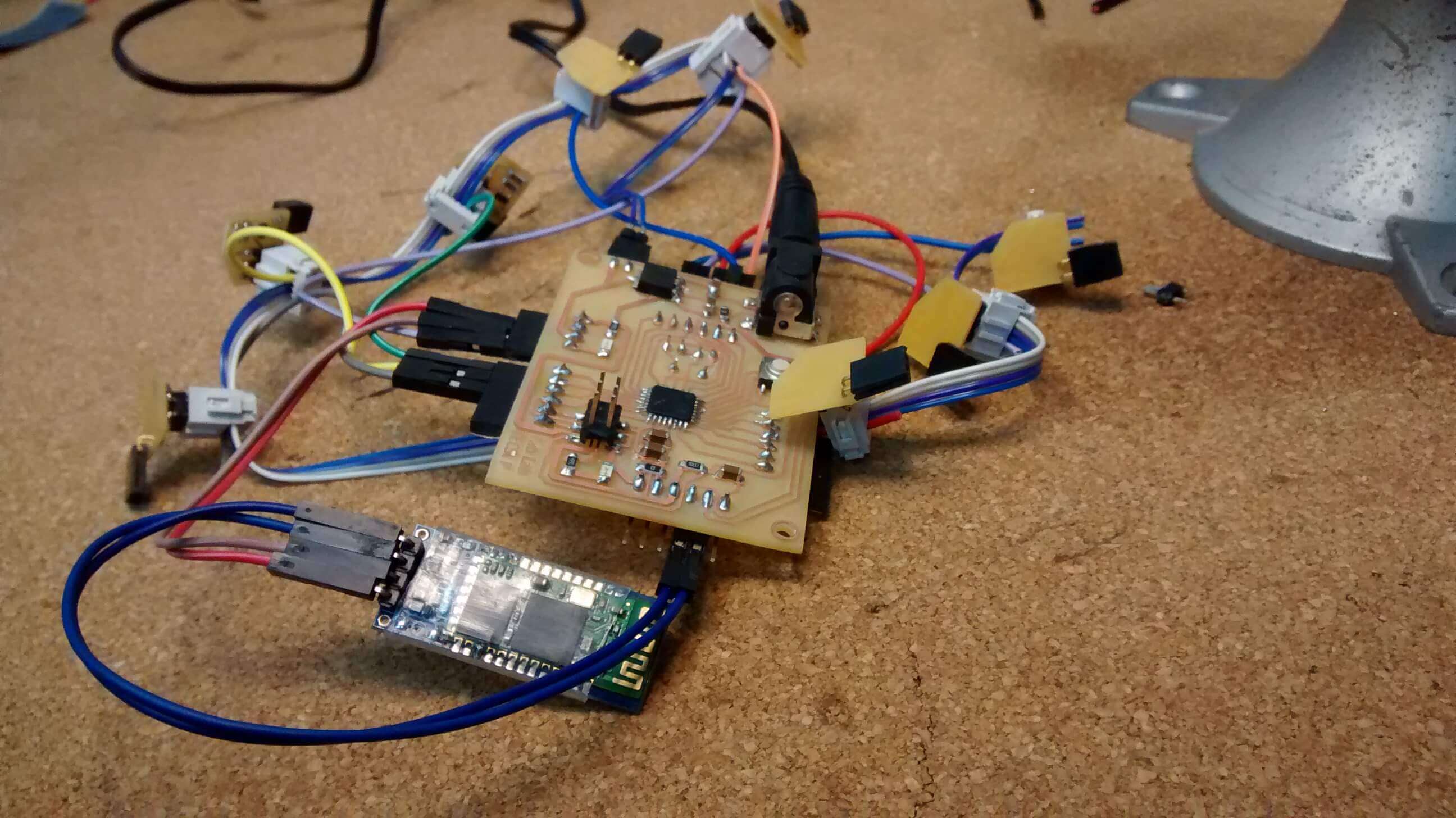
In the electronic, I'm using a Fabduino that is a Fab Lab produced Arduino which in this case has been improved for different students from past Academies in Tecsup laboratory especially José de los Ríos and Roberto Delgado. But i modified some parts in the board, changing the Jack component and adding two pins conector for the power 12V and GND.
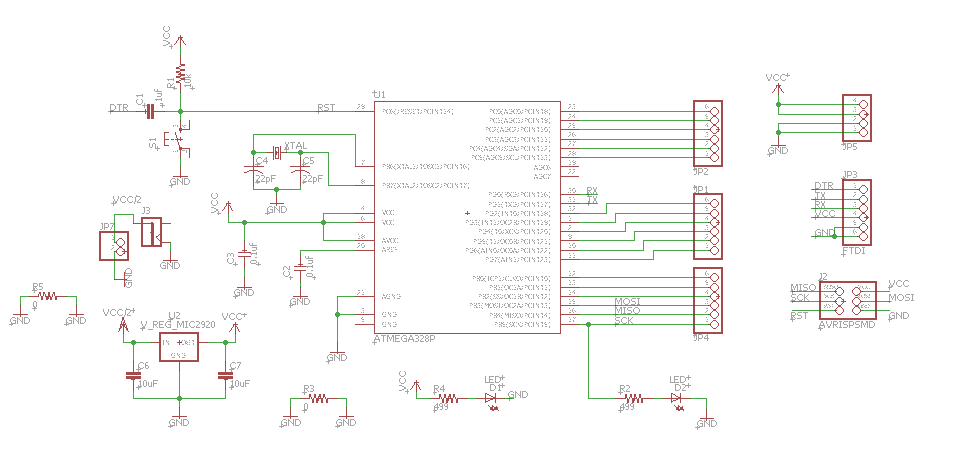
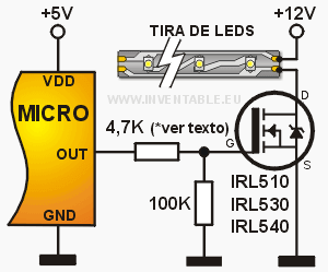
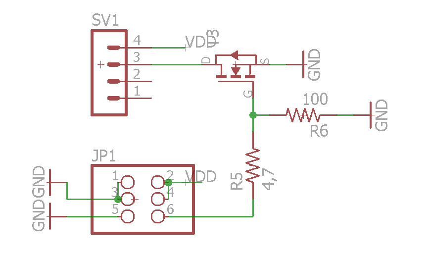
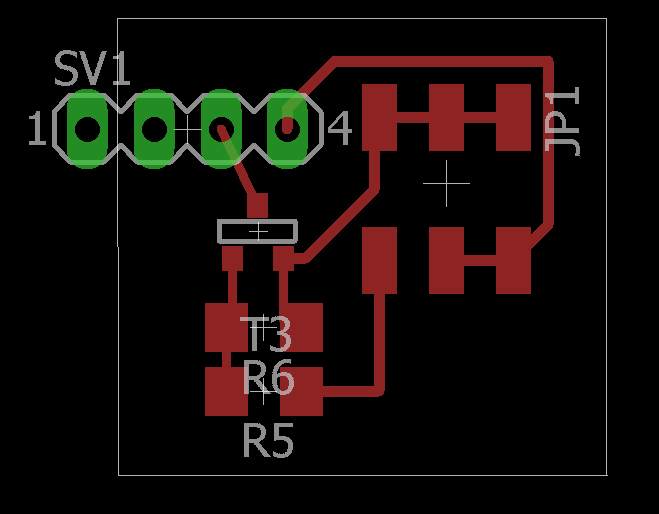
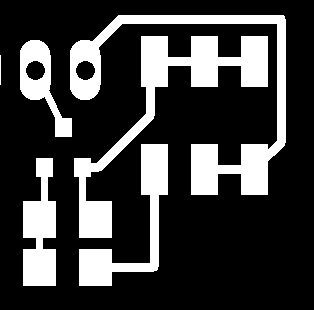
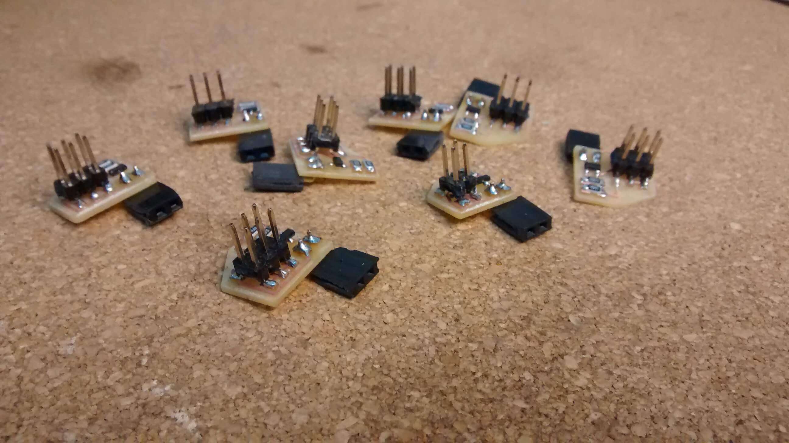
Next thing was to create a small PCB for the LED Strip, with the mosfet and the resistances that will be wired to the Fabduino. I will use eight LED strips and each one have a small PCB.
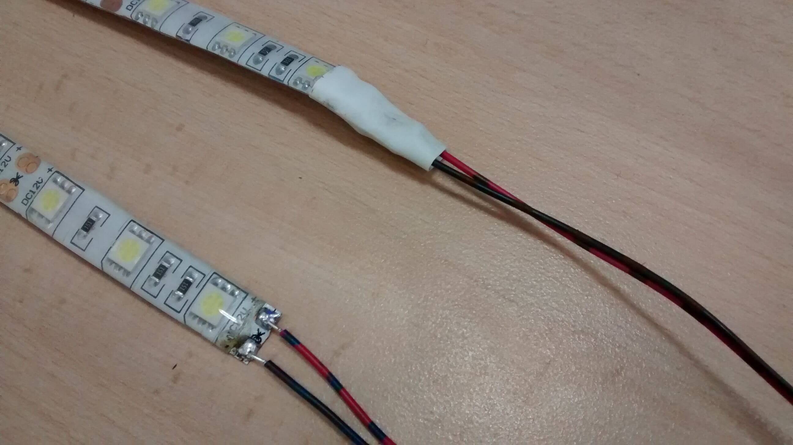
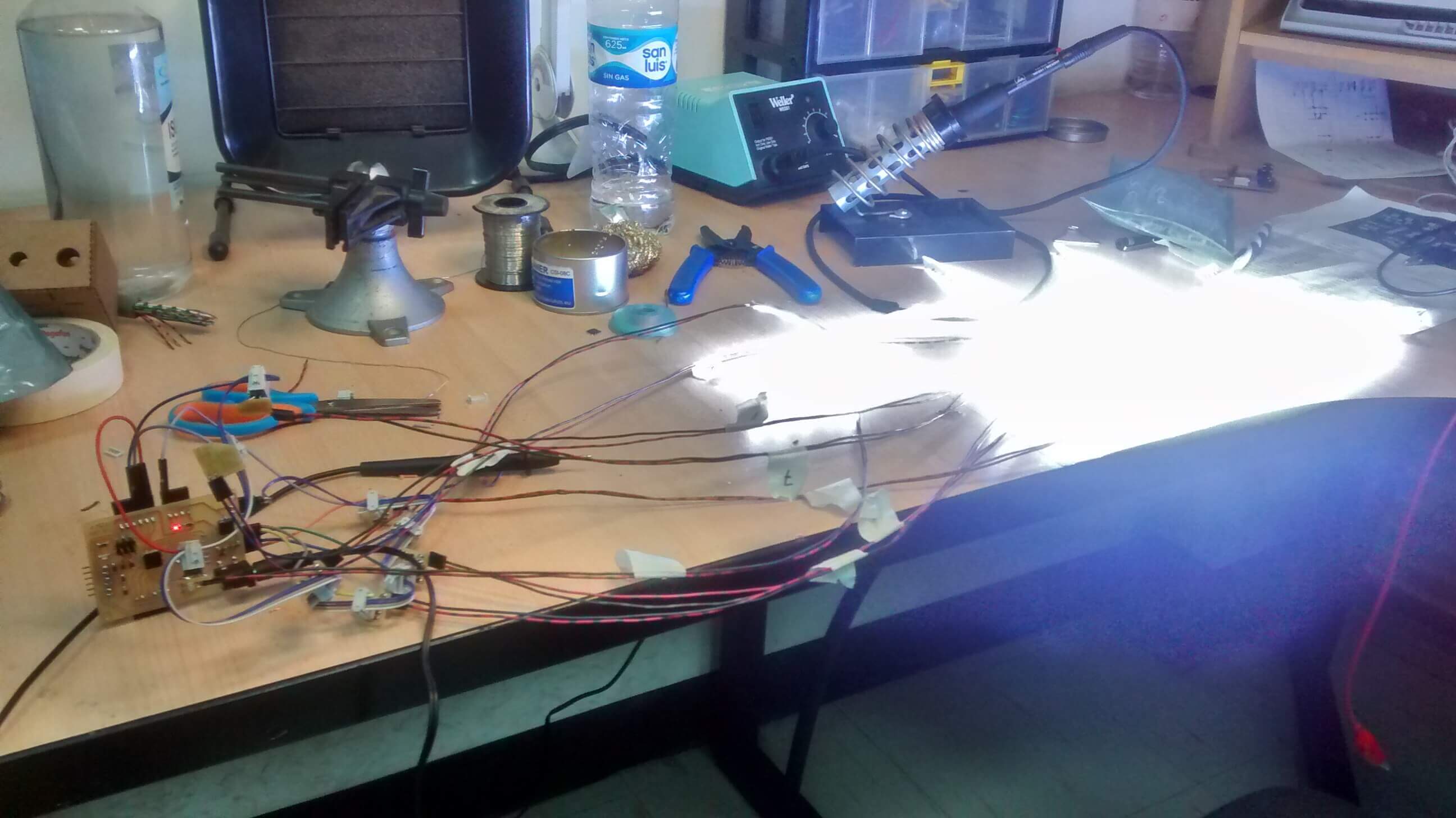
The next step was solder the wires and connect with the bluetooth module in the Fabduino for test.
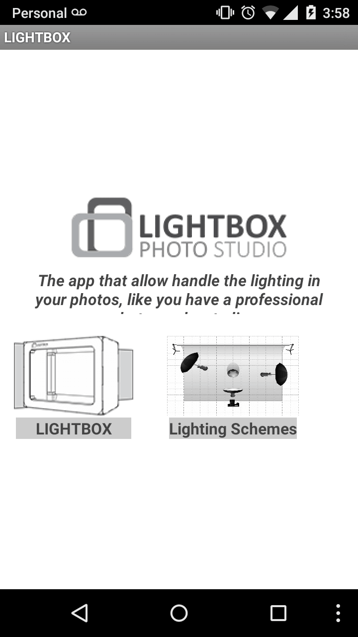
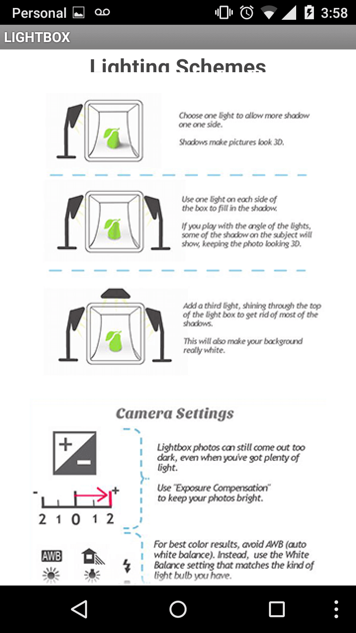
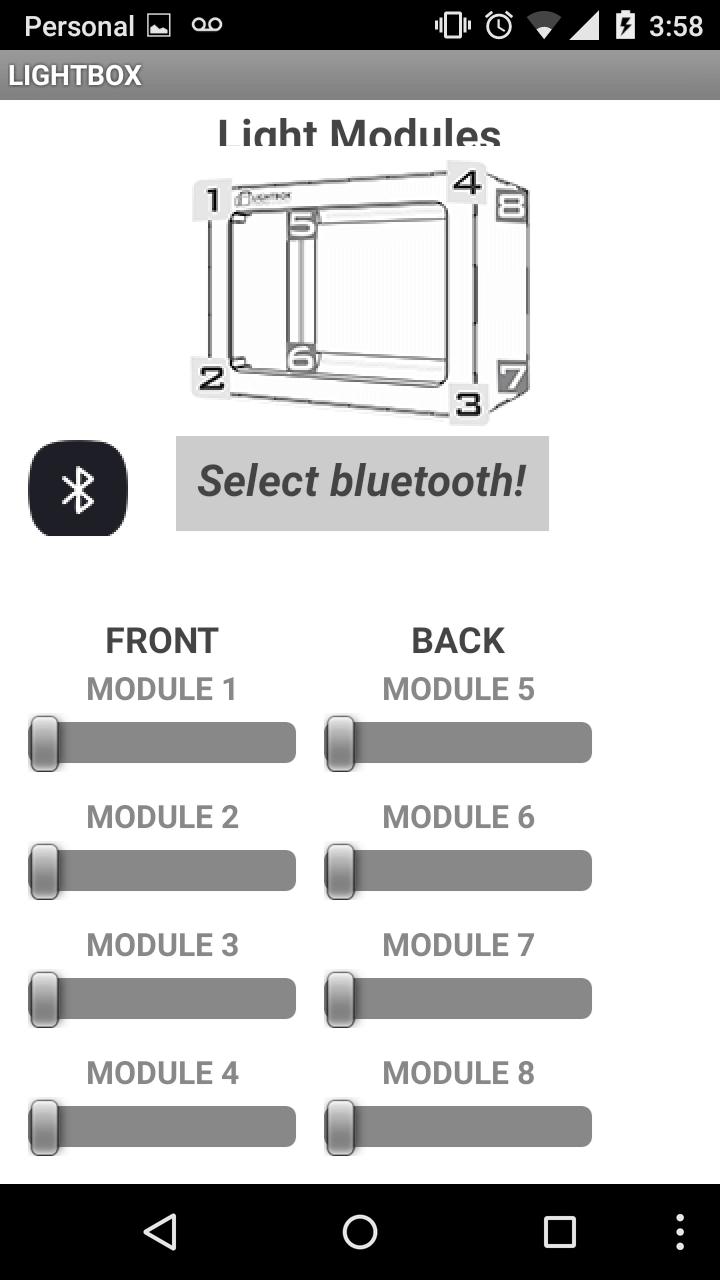
Before to start programming, i designed the App for the cell phone with the MIT App Inventor. It has three screens the first is the introduction and allows you go to the Tutorials screen or Lightbox control screen. In the last one you can control the LED strip luminosity potency when you connect the app with the Lightbox through bluetooth.
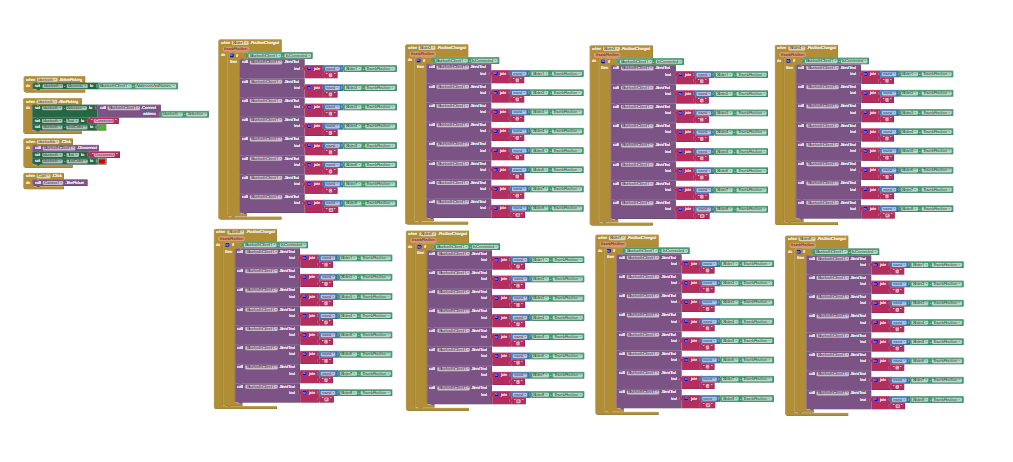
MIT app inventor have a BLOCK screen where you program what you have designed, it's very simple because it use the same system that ardublock, "programming for children". In this case I program how it connect through Bluetooth, and each LED strip slider indicating the maximum and minimum power LED. Also i added a camera button, it allows you go to the phone camera for take the pic.You can see more in the following link App.Inventor clicking on the LIGhtbox2 project each screen have it blocks program.
Also for manage the LED strip with the Fabduino was programed in Arduino using the software serial library.
#include <-SoftwareSerial.h->

SoftwareSerial future(11,12); // RX | TX
int led1=2;
int led2=3;
int led3=4;
int led4=5;
int led5=6;
int led6=8;
int led7=9;
int led8=10;

void setup(){
Serial.begin(9600);
future.begin(9600);

}
void loop(){
 if (future.available()){
  int value1 = future.parseInt(); // Regulador del telefonoAndroid
  int value2 = future.parseInt(); // Regulador del telefonoAndroid
  int value3 = future.parseInt(); // Regulador del telefonoAndroid
  int value4 = future.parseInt(); // Regulador del telefonoAndroid
  int value5 = future.parseInt(); // Regulador del telefonoAndroid
  int value6 = future.parseInt(); // Regulador del telefonoAndroid
  int value7 = future.parseInt(); // Regulador del telefonoAndroid
  int value8 = future.parseInt(); // Regulador del telefonoAndroid
    analogWrite(led1,value1);
    analogWrite(led2,value2);
    analogWrite(led3,value3);
    analogWrite(led4,value4);
    analogWrite(led5,value5);
    analogWrite(led6,value6);
    analogWrite(led7,value7);
    analogWrite(led8,value8);
}}
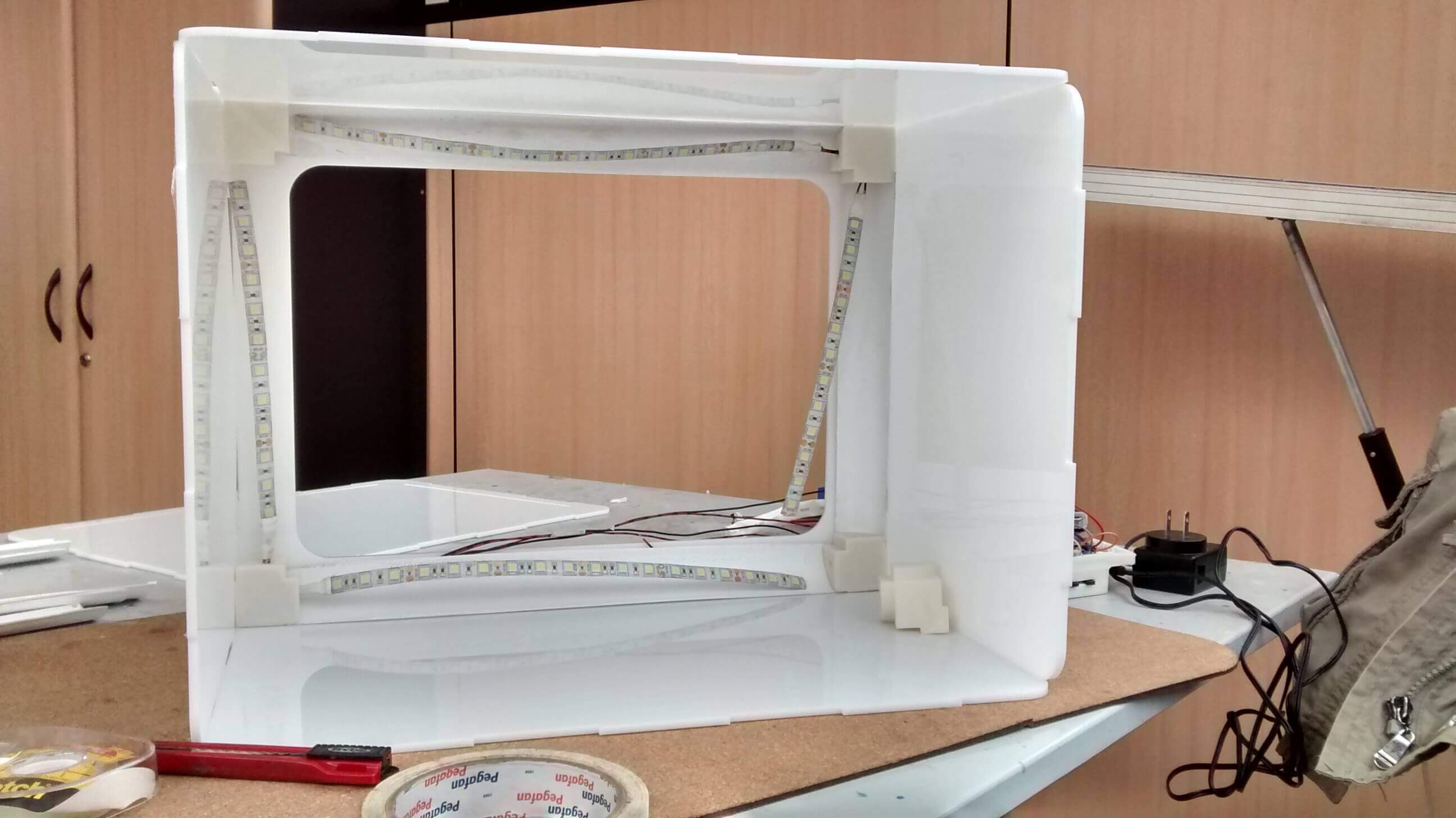
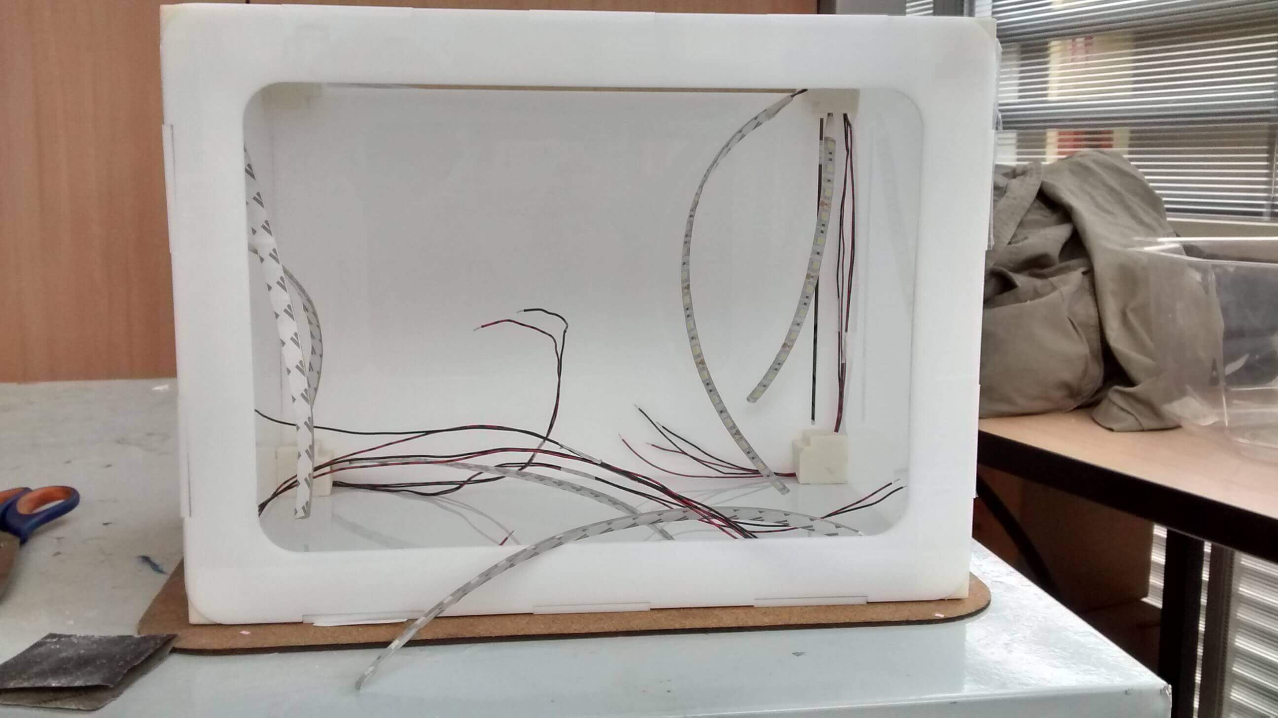
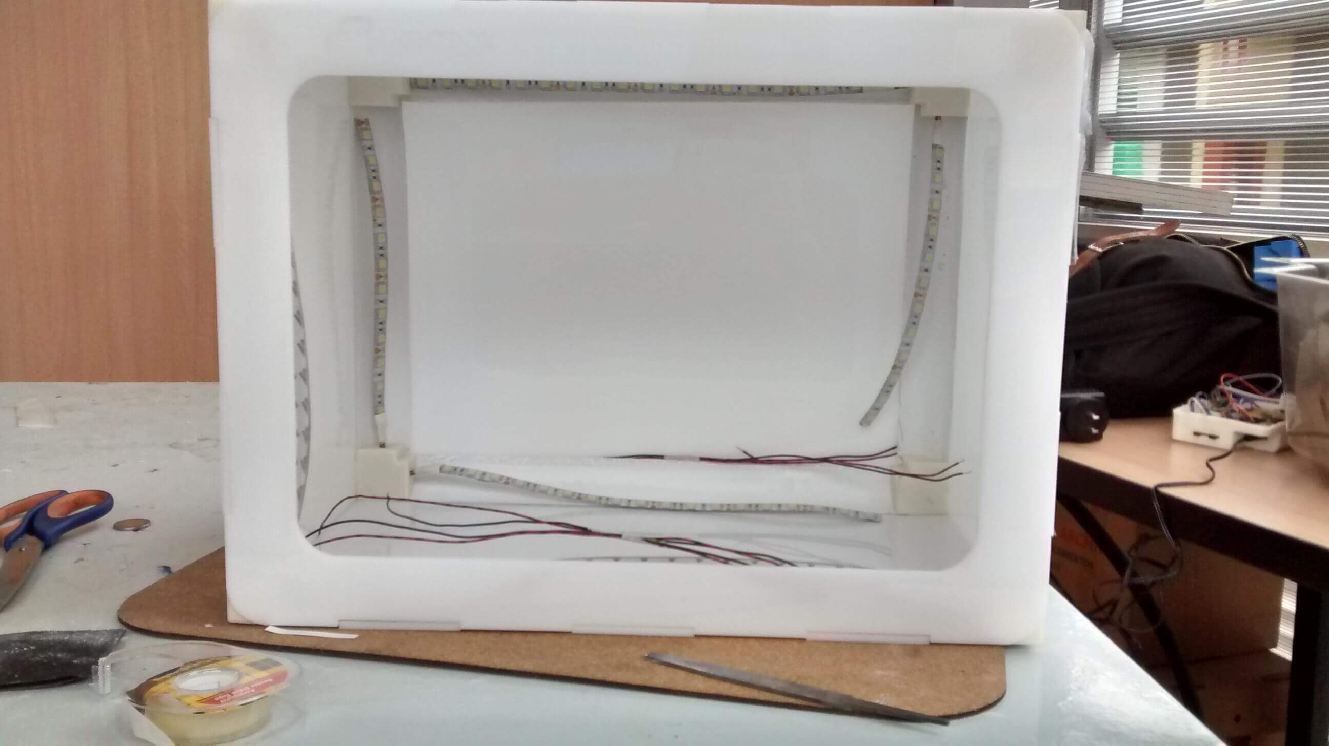
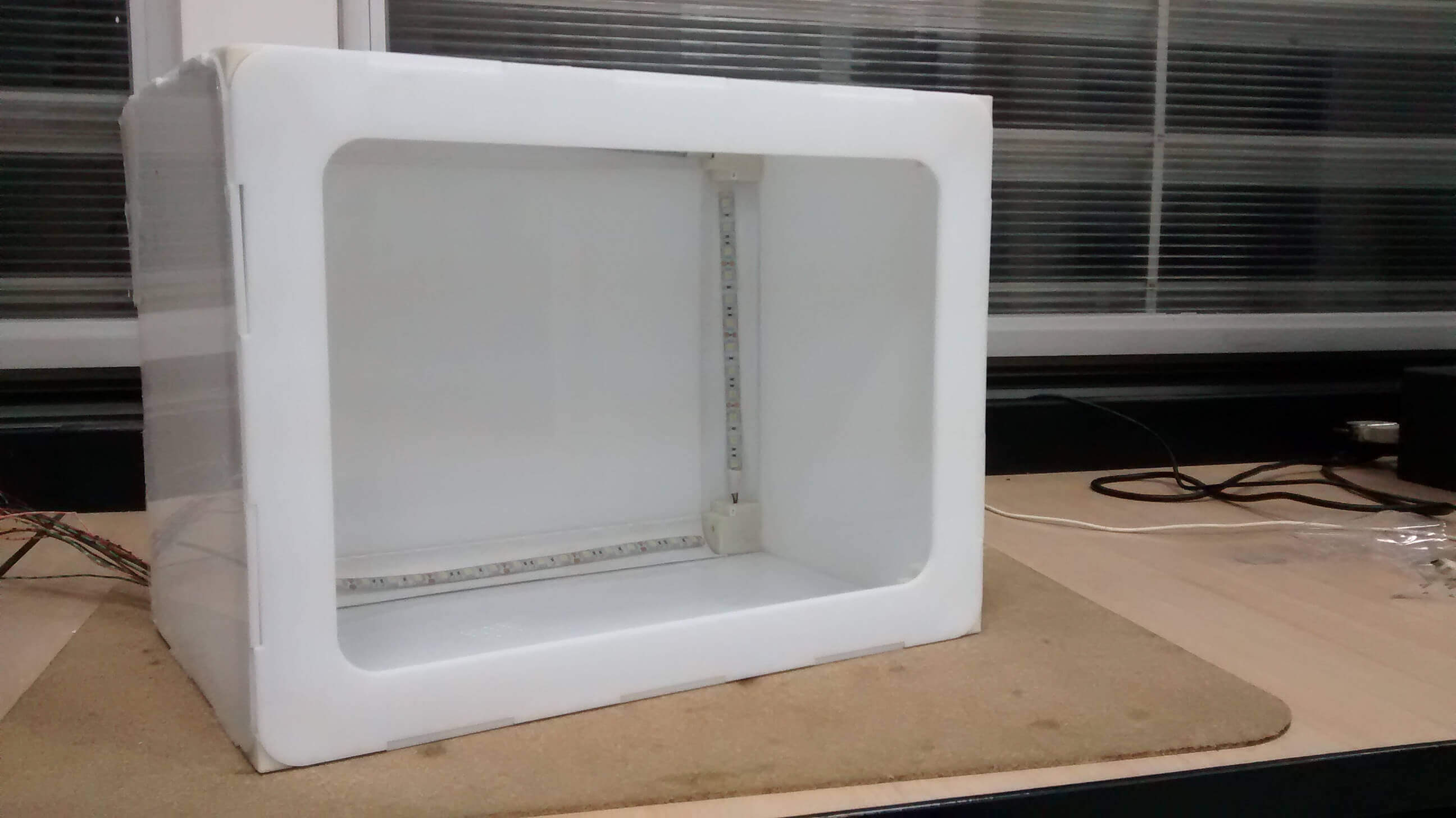
Now we are ready to assemble the Lightbox photo studio, in the following pics and video you can see how i worked.