Output Devices
Satshakit is handy, yet it only comes with one VCC and one GND ground, which is not enough for projects that needs an extra GND or voltage input for a sensor or peripherals.
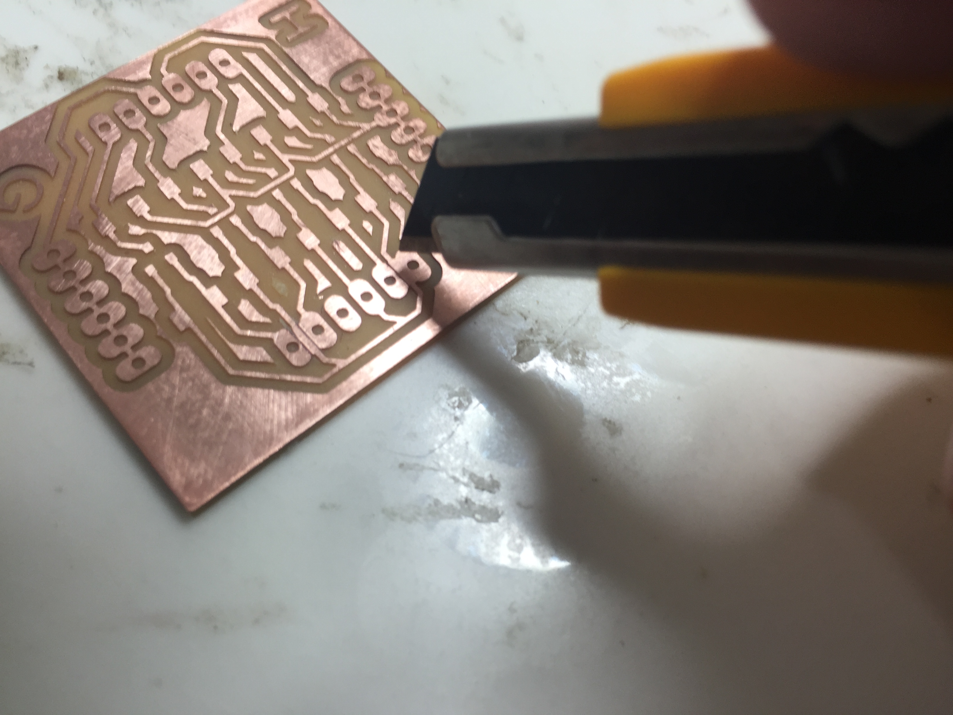
So I designed a board that combines I2C level shifter and VCC/GND extension, see the schematic and the layout in Eagle.
There were two wires too close to pads, so fab module did not finish the route as I expected. I decided to manually repair the glitches by cutting the copper.
This needs to be fixed in a revision, also, the I2C level shifting did not work to my input device, I will figure out what is the problem here.
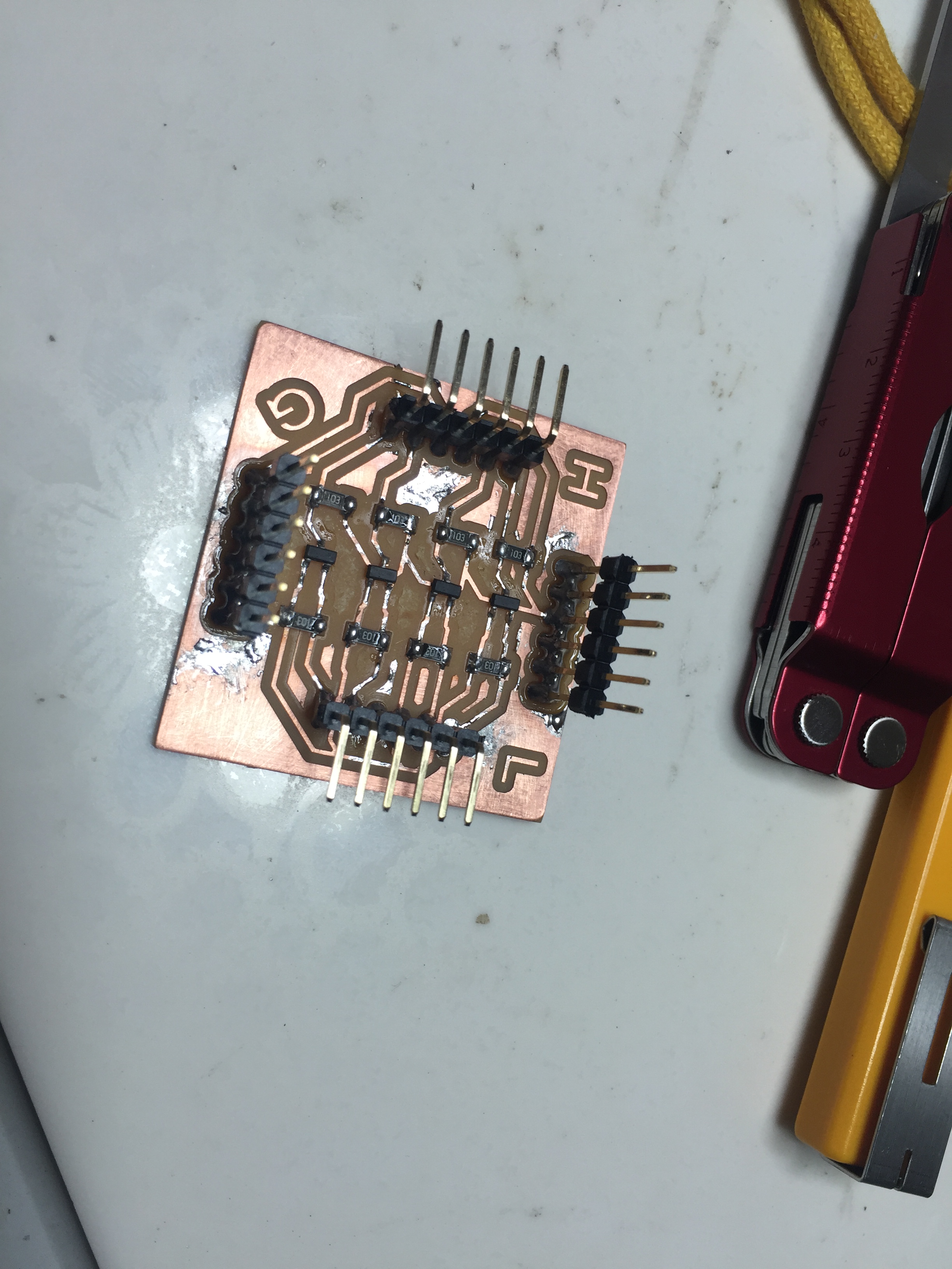
H stands for high voltage input, that is 5V in this case; L for 3.3V low voltage, G for common ground extension.
I decided to make my satshakit output some audio as my first exercise this week.
After some googling, I found this tutorial from High Low Tech.
It was a library for Arduino, still it fits my need anyway, quote:
    The audio playback works using two of the Arduino board’s timers,
    hardware functionality of the AVR (ATmega328) microcontroller that’s
    normally used to generate PWM output with the analogWrite() function.
    One timer is used to generate a high-frequency square wave whose duty
    cycle corresponds to a particular value (amplitude) in the audio sample.
    Another timer is used to update this duty cycle at 8 KHz, the sample rate
    of the audio. As a result of using these timers, PWM output
    (analogWrite()) won’t work on pins 3, 9, 10, or 11. You should still be
    able to use pins 3, 9, and 10 for digital input and output. The audio
    signal will be generated on pin 11.
So I compressed some audio (Neil's voice of course) that I clipped from previous weeks of fab academy, you can download the original .m4a files down here:
Welcome To The Fab Academy.m4a
Note the audio needs to be compressed to 8kHz, you can use EncodeAudio as descirbed in High Low Tech tutorial or use any other tools you like.
Pretty simple, just connect the pin 11 equivalent and gnd to a speaker.
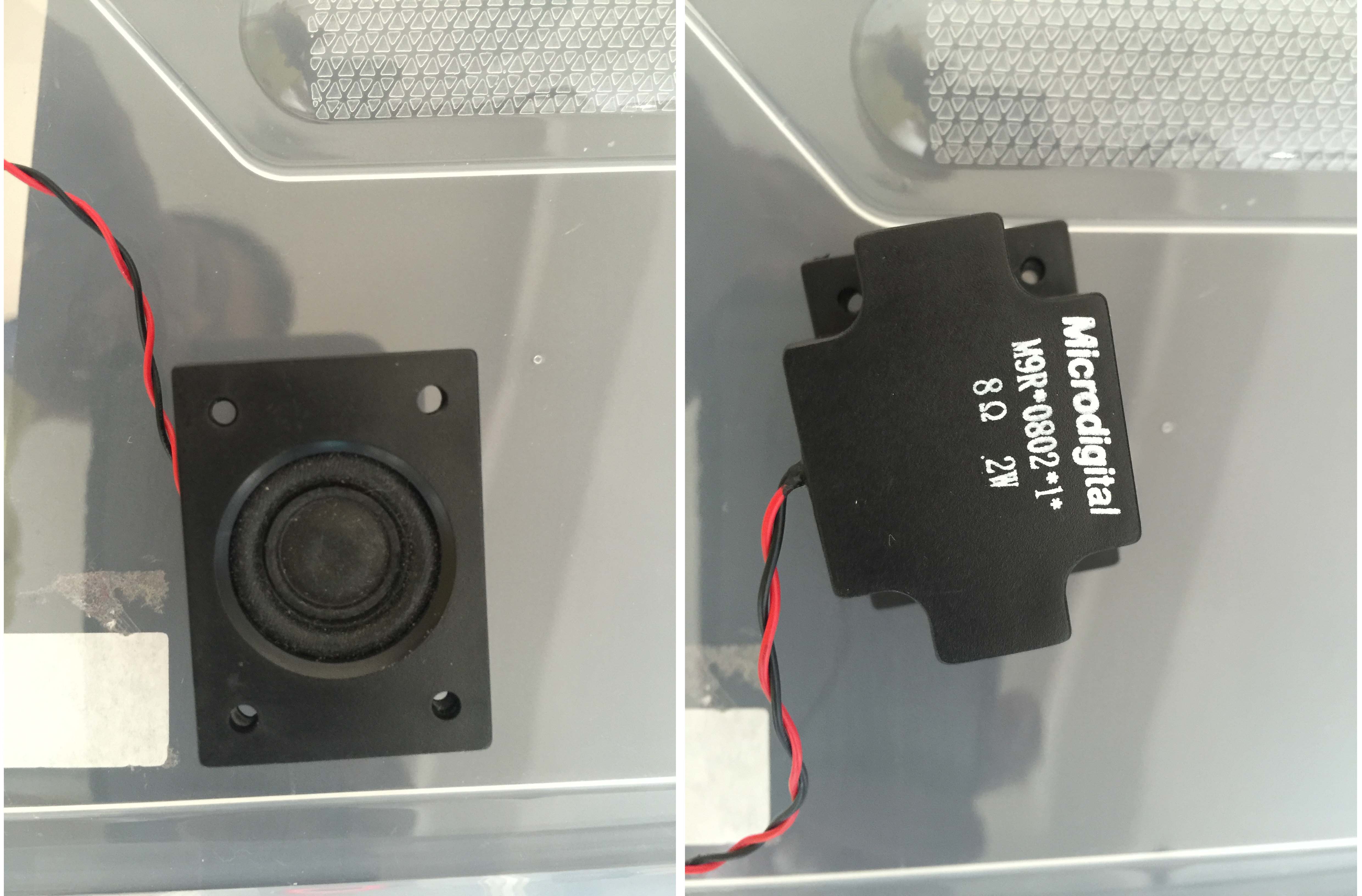
This one is just a random speaker from our lab's inventory. For a 0.2W speaker I could use a amplifier to get better and louder voice, but it does the job for now.
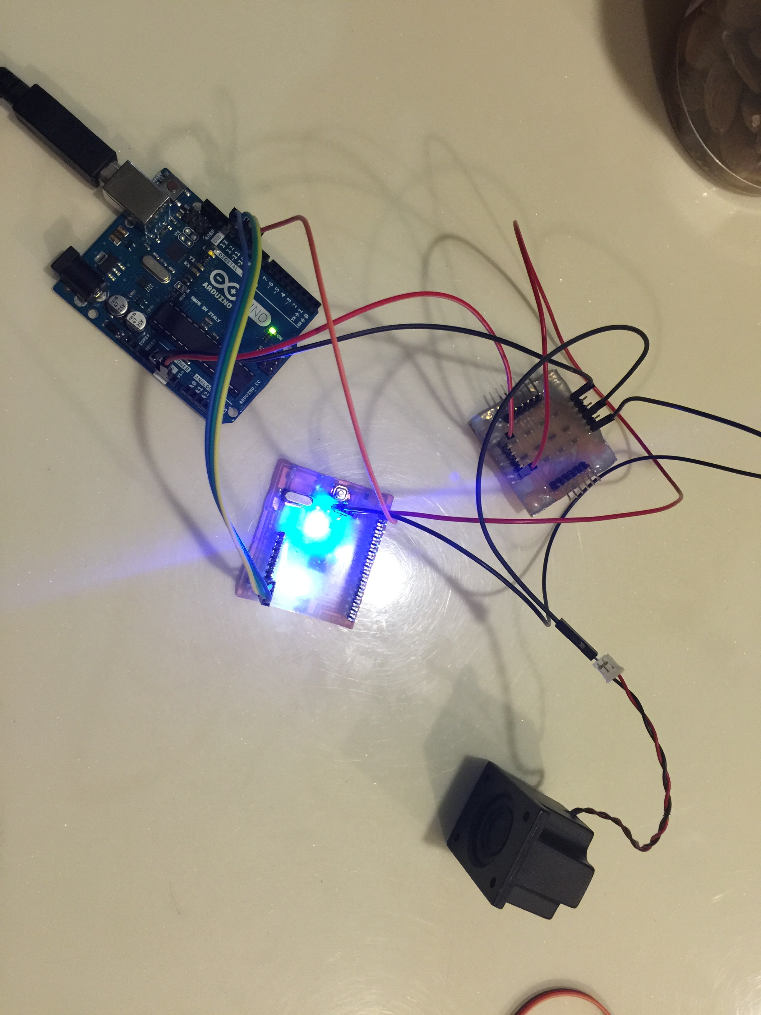
see output device #0 in action on Youtube
WS2812 5050 full RGB LED (2-wire)
(May 04) The LEDs just arrived last Sunday, and I didn't have the time to test it yet...
(May 29) I designed breakout boards for the LEDs, and used Adafruit's NeoPixel library and example code to do the testing.
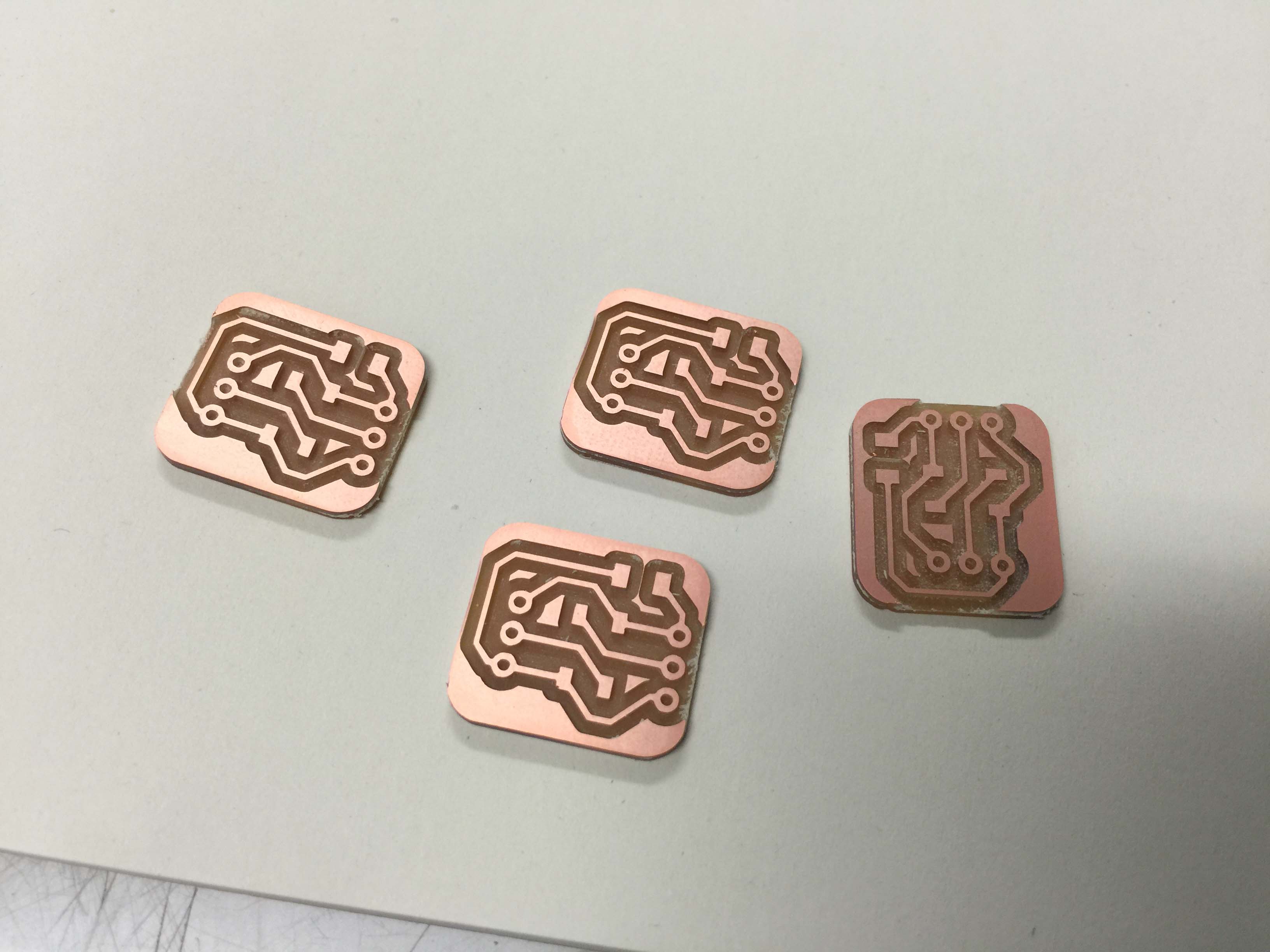
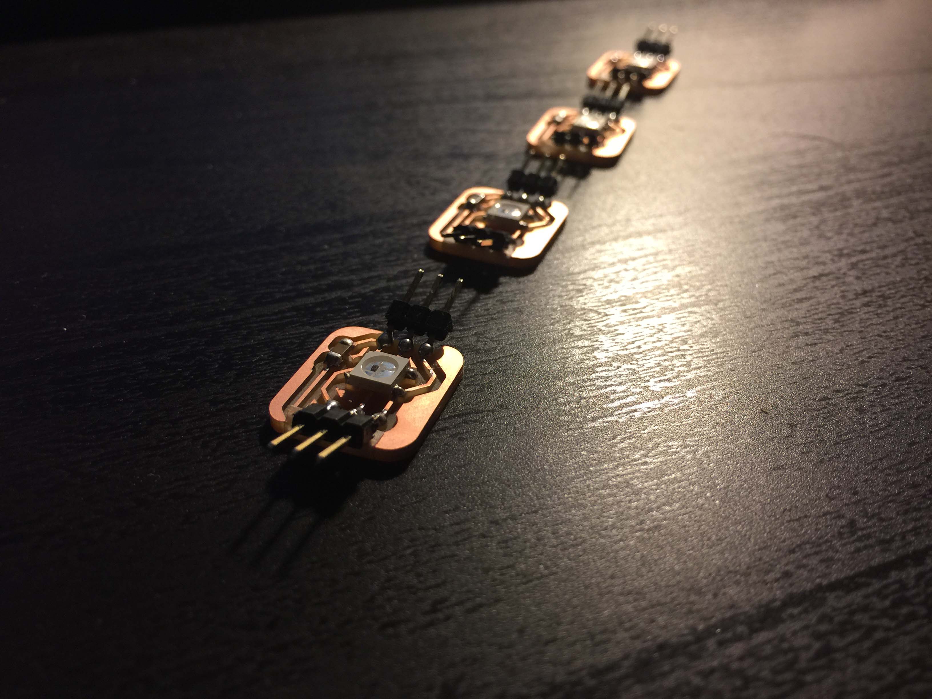
Reference: https://learn.sparkfun.com/tutorials/ws2812-breakout-hookup-guide http://www.learningaboutelectronics.com/Articles/Multiple-I2C-devices-to-an-arduino-microcontroller.php