Week 8 - Embedded Programming
Tasks:
To program week 6 Hello board to do something.
What function can the board perform?
The board has a LED and a push-button. Thus, the function it can perform is not many, for example push the button to turn on/off LED, the LED is turned on/off as long as the button is press-hold, display responds/communicate with monitor when the LED and push-button are activated, etc.
Recalled the schematic done in week 6, the push-button was wired to a pull-up resistor. Which means input pin (indicated as 'sw') would read high when the button was not pressed, i.e. Vcc. When the button was pressed, ground ('GND') would be connected. The pins coding were 'PA7' and 'PA3' for 'LED' and 'Push-button' respectively.
ATTiny44A Datasheet
The micro-controller used in this task is Atmel ATtiny44A. The datasheet can be obtained from the following.
The following shows the pin configurations of the micro-controller and important parameter to note.
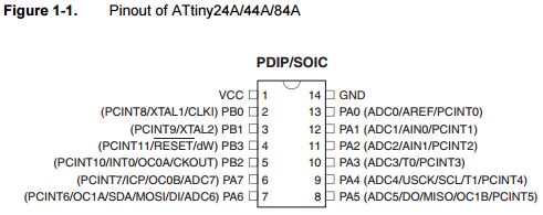
Key Parameters to take note.
Characteristics of the ATtiny44A:
- Flash stores the compiled program even when the power is off.
- SRAM saves temporarily variables while calculating.
- EEPROM is for data storage.
This task will use Arduino UNO as ISP. Arduino IDE was used due to the easy-to-use UI feature for beginner (like me) who is not familiar with command line like avrdude, gcc, ... The user will just need to compile and upload the file. Thus, faster, easier and less demanding on user side. Anyway, the following shows the step-by-step using Arduino IDE.
- Install Arduino IDE>> launch the software>> opened/loaded the ArduinoiSP from 'File>Examples>ArduinoISP>ArduinoISP'.
- Install Attiny support into Arduino at 'File> Preferences> Additional Boards Manager URLs:'. Paste https://raw.githubusercontent.com/damellis/attiny/ide-1.6.x-boards-manager/package_damellis_attiny_index.json. This step is performed based on cohort-mate suggestion, more detail can be found from this link.
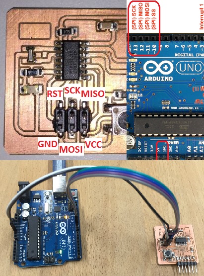
- Wire the Arduino board and Hello board as shown.
- Burn the bootloader
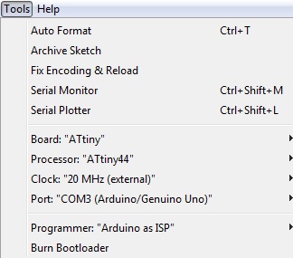
- Go to 'Tools>Board:>ATtiny'
- Go to 'Tools>Processor:>ATtiny44'
- Go to 'Tools>Clock:>20 MHz (external)'
- Go to 'Tools>Port:>COM3 (Arduino/Genuino Uno)'
- Test the Hello board using basic available Arduino example: Blink Go to 'File>Examples:>01.Basics>Blink'. Replace pin 13 to pin 7 since the LED in hello board is connected at pin 7. Click 'Upload' to upload the program into hello board. The following shows the blink program.
| Arduino Uno | Hello Board |
|---|---|
| Pin 13 (SCK) | SCK |
| Pin 12 (MISO) | MISO |
| Pin 11 (MOSI) | MOSI |
| Pin 10 (SS) | RST |
| 5V | VCC |
| GND | GND |
What is bootloader? It is the little program that runs when the micro-controller board is turned on, or the reset button is pressed. Its main function is to wait for the software on the computer to send a new program for itself or other micro-controller boards, which it then writes to the memory. It is a .hex file that runs when the board is turned on. It is very similar to the BIOS that runs on your PC. When the computer is not uploading any sketch/program, the chip will run the program stored in memory. The program will continuously run so as long as the board has power.
Before burning the bootloader, the following steps need to be done, ie. to inform ISP what board/processor/clock/port it is installing.
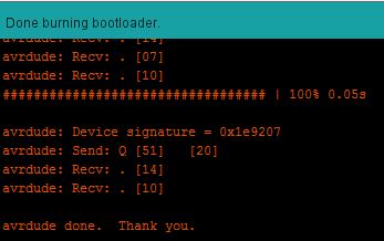
Lastly, Go to 'Tools>Burn Bootloader'. When finished and succeeded, the following message shall be seen.
LED blinks continuously at every 1 second.
void setup() {
// initialize digital pin 7 as an output.
pinMode(7, OUTPUT);
}

// the loop function runs over and over again forever
void loop() {
  digitalWrite(7, HIGH);   // turn the LED on (HIGH is the voltage level)
  delay(1000);             // wait for a second
  digitalWrite(7, LOW);    // turn the LED off by making the voltage LOW
  delay(1000);             // wait for a second
}
Result: Blink every 1 sec continuously.
When replacing 1000 into 100, the blink will be faster, ie. every 0.1 sec.
Result: Blink every 0.1 sec continuously.
LED is turned on only when push-button is pressed.
// set pin numbers:
const int buttonPin = 3;     // the number of the pushbutton pin
const int ledPin =  7;      // the number of the LED pin

// variables will change:
int buttonState = 0;         // variable for reading the pushbutton status

void setup() {
  // initialize the LED pin as an output:
  pinMode(7, OUTPUT);
  // initialize the pushbutton pin as an input:
  pinMode(3, INPUT);
}

void loop() {
  // read the state of the pushbutton value:
  buttonState = digitalRead(buttonPin);

  // check if the pushbutton is pressed.
  // if it is, the buttonState is LOW:
  if (buttonState == HIGH) {
    // turn LED off:
    digitalWrite(ledPin, LOW);
  } else {
    // turn LED on:
    digitalWrite(ledPin, HIGH);
  }
- Firstly, download putty.exe to run/display the communication.
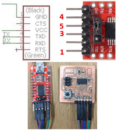
- FTDI USB-to-TTL converter to receive/transmit data
#include <SoftwareSerial.h>
// constants won't change. They're used here to
// set pin numbers:
const int rx=1;
const int tx=0;
const int buttonPin = 3; // the number of the pushbutton pin
const int ledPin = 7;    // the number of the LED pin

int state = 0;      // the current state of the output pin
int reading = 0;    // the current reading from the input pin
int previous = 0;   // the previous reading from the input pin
int flag = 0;

SoftwareSerial mySerial(rx,tx);
// variables will change:
int buttonState = 0; // variable for reading the pushbutton status

void setup() {
mySerial.begin(9600);
mySerial.flush();
mySerial.println("Hello World");

// initialize the LED pin as an output:
pinMode(ledPin, OUTPUT);
// initialize the pushbutton pin as an input:
pinMode(buttonPin, INPUT);
}

void loop() {
if (mySerial.available() >0 ){
state = mySerial.read();
flag = 0;}
reading = digitalRead(buttonPin);
if (reading == HIGH && previous == LOW) {
      state = 1 - state;
      flag = 0;
      delay(10);
      }
      previous = reading;

if ((state == 1) && (flag == 0)){
    digitalWrite(ledPin, HIGH);   // turn the LED on
    mySerial.println("LED is ON! Press button again to OFF it");
    flag = 1;}
else if ((state == 0) && (flag == 0)) {
    digitalWrite(ledPin, LOW);
    mySerial.println("LED is OFF! Press button again to ON it");
    flag = 1;
    }
else {}
}
#include <SoftwareSerial.h>
// constants won't change. They're used here to
// set pin numbers:
const int rx=1;
const int tx=0;
const int buttonPin = 3; // the number of the pushbutton pin
const int ledPin = 7;    // the number of the LED pin

int state = LOW;      // the current state of the output pin
int reading;           // the current reading from the input pin
int previous = LOW;    // the previous reading from the input pin
int flag = 0;

SoftwareSerial mySerial(rx,tx);
// variables will change:
int buttonState = 0; // variable for reading the pushbutton status

void setup() {
mySerial.begin(9600);
mySerial.flush();
mySerial.println("Hello World");

// initialize the LED pin as an output:
pinMode(ledPin, OUTPUT);
// initialize the pushbutton pin as an input:
pinMode(buttonPin, INPUT);
}

void loop() {
if (mySerial.available() > 0){
state = mySerial.read();
flag = 0;}
reading = digitalRead(buttonPin);
if (reading == HIGH && previous == LOW) {
      state = 1 - state;
      flag = 0;
      delay(10);
      }
      previous = reading;

if (state == 'a')
      {digitalWrite(ledPin, HIGH);
      mySerial.println("LED is ON. Press 's' to off it.");
      delay(1000);}

else
      {digitalWrite(ledPin, LOW);}
}