This week's assignment
- Test output device examples
- Modify the exmaples
- Design my ouwn board
RGB LED eaxmple
For this week's assignment, I want to make a simple led module which can be easily used. With pin connector, I can use with any other deivces.
First thins I did was test eamples a hello rgb led board from and archive.
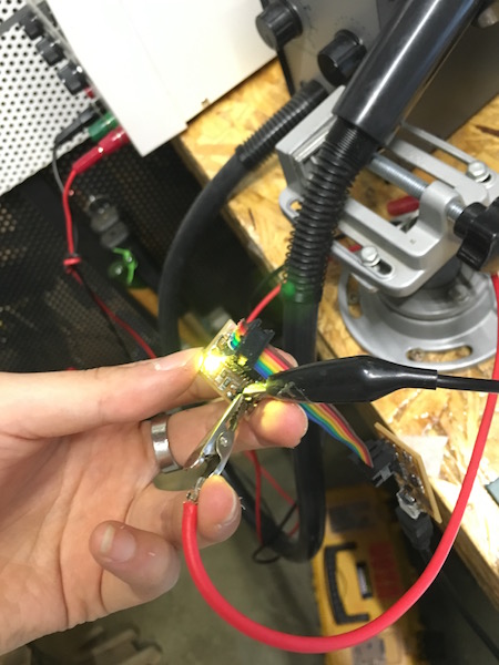
I tested colour changed with example C code and it works well!
Design RGB LED board
But as I mentioned previous week, I want to use only one processor connected with several different input and output devices. So I don't need a ATtiny on my led board. So in my design, I eliminated the Attiny and just added a male connector.
Also we have different RGB led in our local fab lab inventory, so value of resistances must be changed. Please check the data sheet. Here is the datasheet of I used.
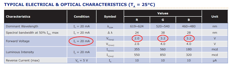
In the datasheet, you can find the forward voltage under the normal condition(here, with 20mA of forward current). It means red colour works between 2.0 ~ 2.6 V (forward voltage). Mainly I will use a one power source and it will be 5V which means it will break the led. That's why we need a resistance. In this website you can calcuate the value of resistance needed for led. I need a 120 ~ 150 ohm for red led and 50 ~ 90 ohm for blue and green. I just used resistors which has similar value.
Programme RGB LED board

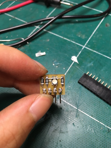
As you can see in the picture above, I used common anode LED. It means 3 colour led share the power supply. So the pin of common anode should be connected power supply and each colour pins should be connected separately and we control by using PWM.
For anybody who are not familiar with the concept of PWM, please take a look this.
Since I used common anode, my code should be different. It means if I want to make a white light, I have to pregramme the 0% of duty cycle(ananlogWrite(0)) to every pins. Also if I want to make a red light, I should programmed red pin has 0% duty cycle and 100% for the other pins.
Results
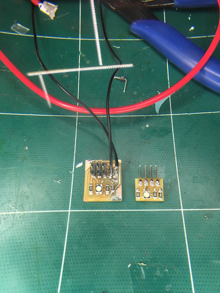
So here's the example board and my own. It has smaller siaze thanks to removing ATtiny and 6pin connector!
Design & Codes Files
downloadConclusion
What I succeeded
- Tested example
- Modify the design
- Add a button and LED
What I didn't do yet
- Check the operation of the board
| ← week13 | molding and casting | week15 | composite → |
|---|