15.NETWORKING AND COMMUNICATIONS
May 11, 2016
This week's assignments are to design and to build a wired &/or wireless network connecting at least two processors.
I decided to experiment the I2C protocol because I used the serial protocol to communicate between the board and my pc in past assignments.The I2C is a wired protocol that uses only two wires. And not only two devices but also multiple devices can communicate each other.
15-1.Set up for programming an ATtiny with Arduino
First, I set up Arduino while referring to this.---
[Reference]
- High-Low Tech – Programming an ATtiny w/ Arduino 1.6 (or 1.0)
- Arduino Playground - USIi2c

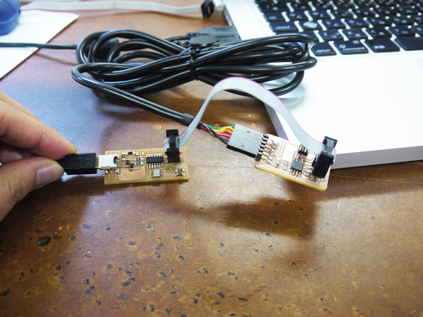
15-2.Make the I2C board
For this assignment I made used this data as reference.Data > hello.I2C.45.bridge.png / hello.I2C.45.node.png
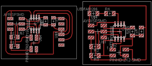
I designed a schematic and a board with Eagle. The drawing of a board went through some changes, that finally resulted in this. I designed it that there was "6pin FTDI header" on a board properly. And components that I used are as follows.
---
[Components / Bridge]
- AVRISP x1
- 6pin FTDI header x1
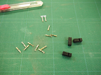
- 2x2 Pinheads connector x1
- 10k Resistor x 3
- 1uF Capacitor x1
- AT tiny45 x1
[Components / Node]
- AVRISP x1
- 2x2 Pinheads connetor x1
- 10k Resistor x3
- 499 Resistor x1
- 1uF Capacitor x1
- AT tiny45 x1
- LED x1
[Data]
- Bridge: hello_i2c_bridge_160516.brd / hello_i2c_bridge_160516.sch
- Node: hello_i2c_node_160516.brd / hello_i2c_node_160516.sch
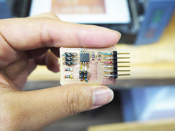
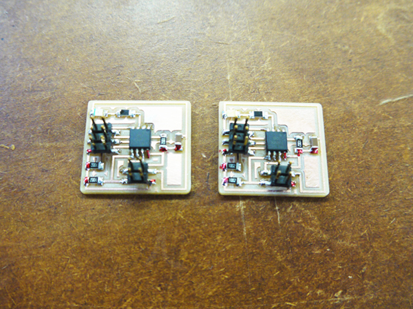
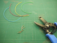
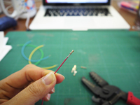
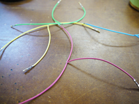
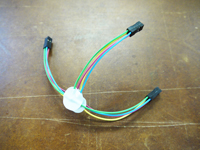
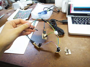
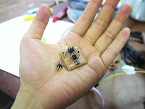
Then I cut a board and soldered components. I made one the bridge board and two the node boards. And I colored boards to make it easy to understand places of VCC and Ground.(In addition, it became a little pretty.)
---
[Data]
- Bridge: hello_i2c_bridge_trace.png / hello_i2c_bridge_cutout.png
- Node: hello_i2c_node_trace_2.png / hello_i2c_node_cutout_2.png

Then I tried to program while referring to this page
---
[Plan]
1. Input a single character from PC.
2-1. If "t" is input:
LED of Node1(Slave1) blinks, and a sentence "Tokyo tower!!!" is displayed by a PC.
2-2. If "s" is input:
LED of Node2(Slave2) blinks, and a sentence "Sky tree!!!" is displayed by a PC.
2-3.If other single character is input:
A sentence "hmm...???" is displayed by a PC.
3.Reset
[The code for the bridge]
[The code for the node1]
[The code for the node2]
---
[Process]
1. Open Arduino,
2. Choose the serial port(/dev/tty.usbserial-********)
3. Open the serial monitor, and enter a number and send.
But, their communication did not go well...
When I input a single character, Sentences("Tokyo tower!!!", "Sky tree!!!" and "hmm...???") were displayed at PC but LED didn't blink.
So I'll try that again one more time.