13.OUTPUT DEVICES
Apr 27, 2016
This week's assignments are to add an output device to a microcontroller board you've designed and to program it to do something.
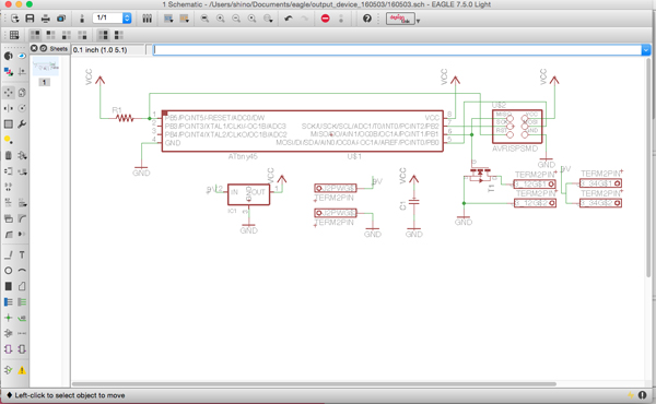
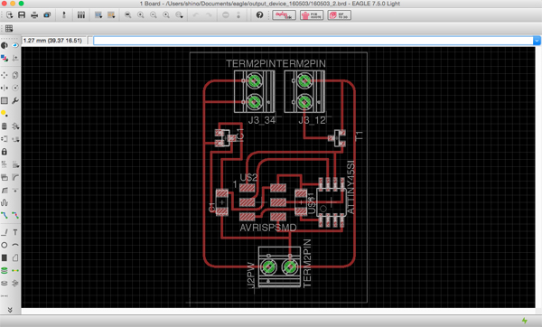
13-1.Board design
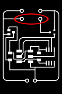
First, I designed a board. For this assignment I choose the speaker. And I used this data as reference.Data > hello.speaker.45.png
Components that I used are as follows.
[Components]
- ATtiny45 x1
- 0.1A/5V Regulator x1
- 1uf Capacitor x1
- AVRISPSMD x1
- 2x2 Pinheads connector x3
- 10k Resistor x1
- MOSFET N
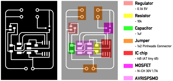
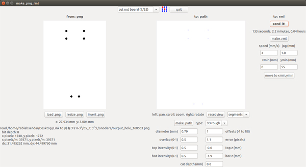
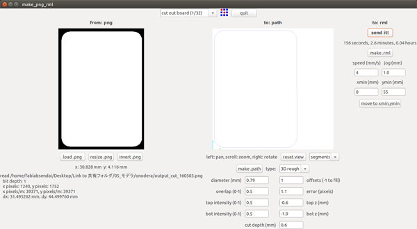
png Data > output_trace_160503.png / output_hole_160503.png / output_cut_160503.png
Eagle Data > 160503_2.sch / 160503_2.brd
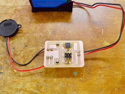
13-2.Assemble

13-3.Programming the board to do 'something'
I used following Neil's program.Data > hello.speaker.45.c / hello.speaker.45.make
And I programed this code by using AVR.

But that sound is very small! So I made a board twice. However the volume of sound remained small...;(