Serial
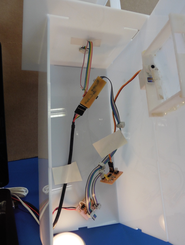
When diving into networking I had my mind set on the I2C protocol wich is called TWI on the avr, and I did a bit of reading up on that and Bas went through how to translate framing of bytes sent through that. when designing my boards I reserved two pins for networking, but what I did not know at the time was that these pins needed to be the exact pins that are built into the avr as TWI pins. So I threw I2C out of the window and networked with the Seral protocol, wich turned out to be much simpler and suited my skill level well. I did the programming through the Arduino IDE. My Temprature Sensor Board would act as a master of the network, equiped with an AtMega328 The 6pin programming header on the board just had to double as a networking pins. The baudrate for communicating with the computer is 9600, but between the boards its 4800.
To get going with the Serial I got opened an Example of a serial sketch in Arduino. In the file menu choose: Sketch -> include Library -> Manage libraries. There I found SoftwareSerialWithHalfDuplex. Then in the file menu choose: File -> Examples -> Serial -> SoftwareSerialWithHalfDuplex-master -> SoftwareserialExample to open up a sketch to work from. I copied what I needed from that code into My DHTsensor sketch.
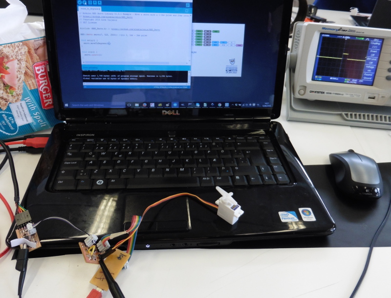
To edit this sketch the first thing I needed was to include the library in the sketch and then within SoftwareSerialWithHalfDuplex() I defined the pin number that I used as the transmit and recieve pins(rx, tx) those pin numbers were 12 and 13, as found out when looking at a pin mapping image for the Arduino. After that it was just a question of setting the baudrate. Now I could communicate with the servo board so what I did is I sent out an ID number "7" that I already asigned the Servo board, then I delay for 2ms so I dont flood the board, and after that I send out "o","m","l" wich the Servo board recognizes and opens the windows accordingly.
On the servoboard I added to my Move_to_degrees sketch and added to it the SoftwareSerialWithHalfDuplex library and set the baud rate, and then give the Servoboard an ID, for wich I choose "7", then I needed to define wich pins would be used for the networking, they were pins nr. 1 and 0. Now in the main loop the servo updates if the serialport is available and moves to certain possitions according to wich character it receives.
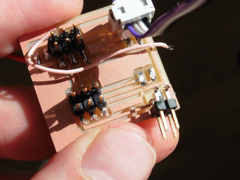
I made a hub where I could change from 6 pin to 4 pin headers and then have a seperate header for the Servo and stepper that ran on 12V and I needed to change from the 6pin headed on the AtMega328 board to the 4pin header of the servo board. in the end I didnt use the Stepper and just ran the Servo on 5 volts but still I used the board to change between header sizes. This hub gave me some troubles as by some reason two of the traces were not routed properly apart so I had do seperate them with an utility knife. At some point I let the 24V from the Servo to the Stepper header with a jumperwire, but in the end I could remove it.