DHT11
I did not refer to the datasheet in this week as I either used code provided, or looked at the microchips pin mapping image for Arduino.
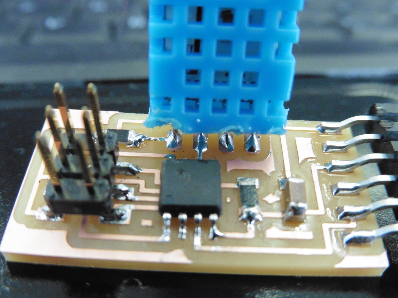
My Assignment this week was to build a board with an microcontroller and a measuring device capable of making measurements of some sort and returning me the data. Since my final project will be somewhat weather related I, along with my fellow student Hafliði decided to go with an AOSONG DHT11 sensor that measures heat and humidity, and Bas happened to have lying around. I Based my design on the Hello.temp.45.cad board provided in this weeks archive, But I looked up the pin arrangement for the sensor in its datasheet and redrew the board in Eagle with these pins routed to their destinations.
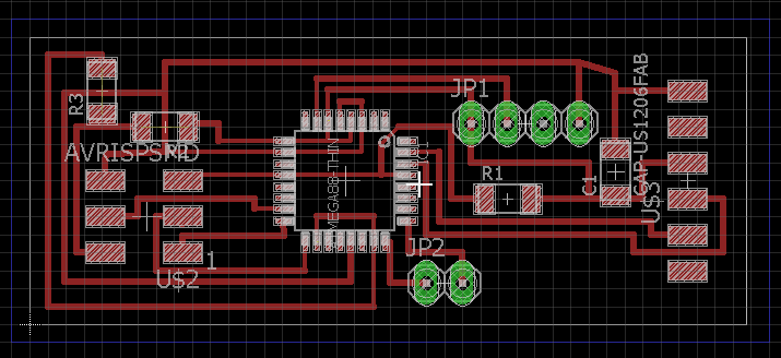
 Revisiting Eagle went better then I expected thanks to my former documentation, It took my some time to locate the menu for libraries but once there I included the library for Pin Headers that make for holes for the sensor pins. I needed to include an jumper-resistor and a picked up a neat trick to rout that, I had it seperate on the schematic with VCC labeled wires on each end so it just wants to route through itself. Exporting the outline and traces took a few attempts, I had to turn layers on and off to get the right one visible, I included Pads and Vias layers to get the pinhead trace in both images its pads come out white in the traces image, on the outline image they dissolve as I fill the plane with white and that only leave the dots black that will be drilled through to the bottom as the outline.
Routing the board on the Roland MX-20 went fine, I looked for the set zero button but its enough to home to a position, that that position acts as zero, I connect the fabmodules through .js node, calculate the path and hit send to get the job going.
Soldering bore the trademark of an shivering old man. not much improvement there. time is one directional.
Communicating with the board: I was a bit lost in communicating with the board, I was hoping it had some echo feature like the Hello World board. At first I tried and tried to to upload the code provided on this weeks page for an alltogether another sensor than DHT11 wich of course was not going to work, I was still trying and trying when my instructor Bas came sniffing up around me saying, with squinted eyes and a rusty voice; "Ahh I love the smell of burnt microcontrollers in the morning.". Turns out I turned the At45 the wrong way round so it was shorted and there was a bulge ontop of it.*(picture)
I replaced the microcontroller and managed to upload the TEMPFILE with winAVR. Of course it did not do anything as the code is for another sensor, but it proved I could connect to the board through the ISP.
I headed over to the arduino enviroment wich I had set up to connect to the At44 in week6 .
I Searched for DHT11 in Inculde Library->Manage Libraries, and choose one library at random, we also included Software Serial library so the board could communicate back to the computer through the serial cable. This didnt work as the library is to big for the Attiny44 so instead of trying to solve that I decided to make an ner board straigth from the repository.
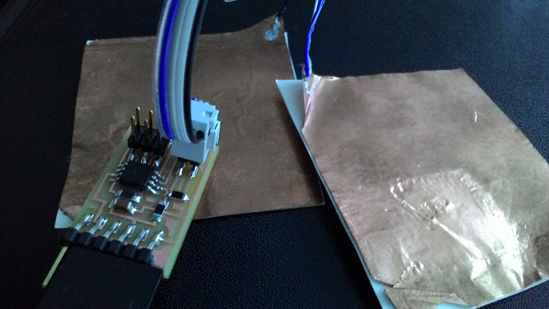
I choose the Transmit-recieve version of StepResponce Board. Its an interresting sensor made out of two seperate copper plates, as I understand one sends an constant pulse of 0and5 Volts and the the other is connected to high-in-value pull- up and down resistors as well as an input pin, so as it its very sensitive to changes around the plate. These measure somehting like electro-magnetc fields.
I downloaded the *Image files of the *traces and outline of the board from the archives and went straight to routing through the fabmodules. Then I soldered and that went quickly and it looked much better than before. I cut out two pieces of glueable copper sheets and connected them to a wire with a 4way connector on the end. I uploaded the provided code to the chip through AVRdude, and started the python script from the repository by typing python hello.txrx.45.py COM4 in command prompt and got some reading but it was clear the not the right wires where connected to the plate, I just looked at the colors of the wires connected in the example video but the connector could have turned any other way in that. Bas helped my measure with the multimeter wich wire led to wich trace on the board and I figured I had to switch one wire, after that it was just voilá (yes I was cheering in french.)
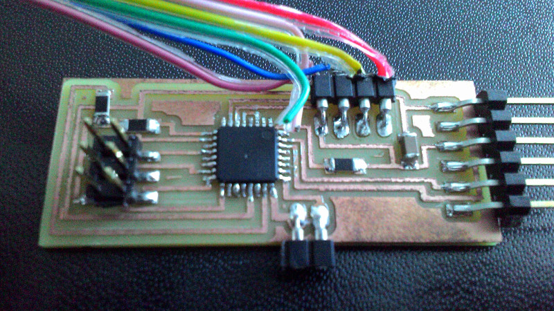
I came back to this week when I had deceided up on a final project. I would make a masterboard for the networked boards that would include an DHT11 and the atMega328 chip that could fit the Sensor Library on. It took some time to locate the right footprint for it but finaly I located the one with thinner pin footprint than the other. Routing that board was a bit complicated as there were so many vcc and ground pins that all had to be connected. And just for fun I included an 2pin header option connected to the Analog to Digital pins to have that option open if I had any ideas in the future. The 6pin programming header doubled as a networking header.
 I programmed the Board in the Arduino IDE by adding Tools -> Board -> Boards Manager... There I selected Atmega328 Breadboard with internal 8mhz clock cicle. And offcourse everytime I program an AVR in the Arduino IDE I select Upload via Programmer rather that upload sketch..
Now I opened the Example sketch that came with the DHT library FILE -> DHT TESTER LIBRARY -> DHT TESTER. To get it working I needed to change a few things. To start with I needed to change the Sensor pin to pin 20 on the AVR.
 I had looked at a pin mapping image for the AtMega in the arduino. And noticed that the the pin PB6 was not utilized as an digital pin on the arduino board and that was the pin I routed my sensor to, I had to enable that by editing the pin mapping file for the arduino library. This is done by editing the pins_arduino.h file found under my local arduino folder in Program files: hardware/arduino/avr/variants/standard/ and the edited version was then saved under \Documents\Arduino\hardware\Breadboard-Arduino\avr\variants\mega328 wich is where my sketches and external libraries reside.
The changes made included adding ,PB twice in the bottom of the "const uint8_t PROGMEM digital_pin_to_port_PGM[]"function so if you count the instances those map out to pin20 and 21
I had looked at a pin mapping image for the AtMega in the arduino. And noticed that the the pin PB6 was not utilized as an digital pin on the arduino board and that was the pin I routed my sensor to, I had to enable that by editing the pin mapping file for the arduino library. This is done by editing the pins_arduino.h file found under my local arduino folder in Program files: hardware/arduino/avr/variants/standard/ and the edited version was then saved under \Documents\Arduino\hardware\Breadboard-Arduino\avr\variants\mega328 wich is where my sketches and external libraries reside.
The changes made included adding ,PB twice in the bottom of the "const uint8_t PROGMEM digital_pin_to_port_PGM[]"function so if you count the instances those map out to pin20 and 21
 and likewise _BV(4), _BV(5), was added to onst uint8_t PROGMEM digital_pin_to_bit_mask_PGM[].
. Then in the code I enable DHT11 instead of DHT22. I added a delay of 2sec in the beginning of the Void Loop(). I edited out the clause that exits if the reading fales and the clause that computes the values in farinheit as I use Celsius. I then simpled down all the data it sends back to only two int variables and a comma for seperation. this would make it much easer for me to work with and interpret the data sent from this board once networked.
and likewise _BV(4), _BV(5), was added to onst uint8_t PROGMEM digital_pin_to_bit_mask_PGM[].
. Then in the code I enable DHT11 instead of DHT22. I added a delay of 2sec in the beginning of the Void Loop(). I edited out the clause that exits if the reading fales and the clause that computes the values in farinheit as I use Celsius. I then simpled down all the data it sends back to only two int variables and a comma for seperation. this would make it much easer for me to work with and interpret the data sent from this board once networked.