 JOSE REAL
Week 3 - Controller computer cutting
We have learned about computer controled cutting, vynil cutting and laser and engraving cutting.
Cutting a Vynil
We use a very simple vynil cutter, Silhouette Cameo. This is a very simple machine. Marta and I have tested it cutting our logos. It's very easy to use, we made our cuts with the Silhouette's software. It's accept png and dxf files. I have design my logo with illustrator and exported to dxf.
|
working with Silhouette Cameo
|
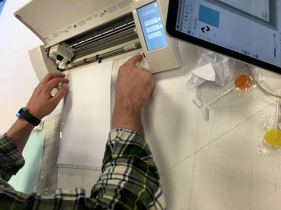
The precision and force of the knife was manual-set, and we could set up the type of paper, size, cutting speed and type (continuous cut or “dashed”) from the application.
|
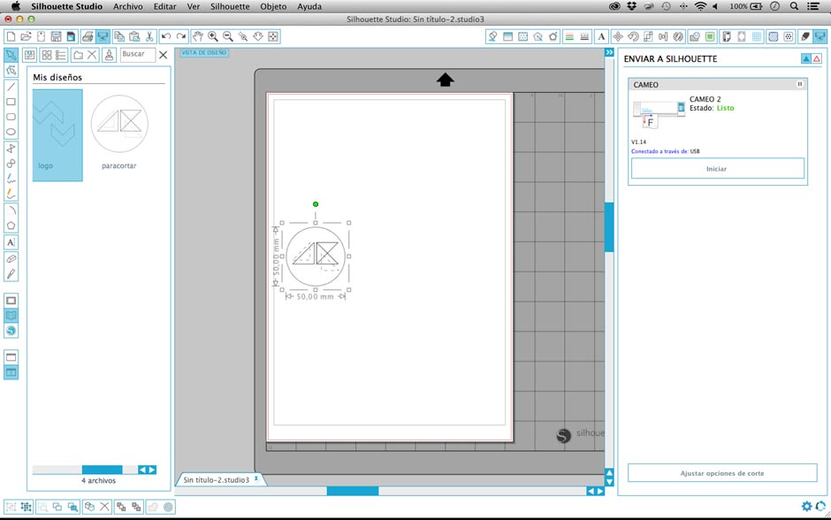
screenshot of Silhouette Cameo Studio
|
|
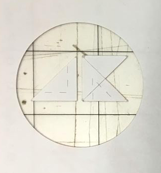
result of cutting
|
|
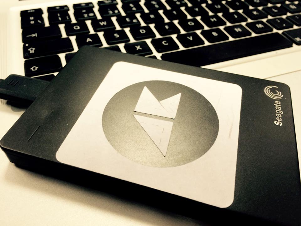
I have adhered to my external HDD!!
|
Laser cutting
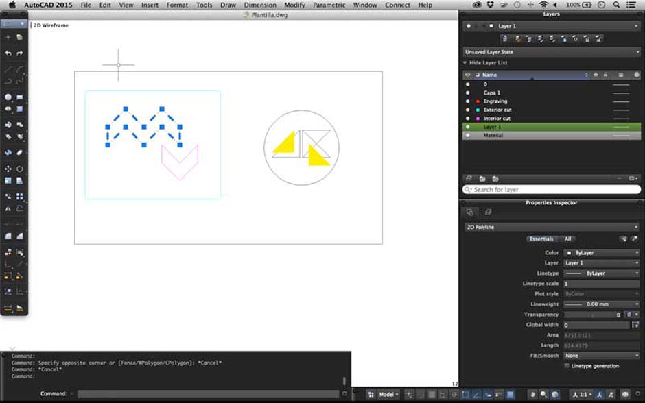
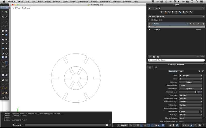
Our laser cutting machine is an Universal VLS 6.60. Also use its own sofware. Firstworks with Autocad, that send to the laser machine the colors layers to cut, engrave and raster. Also in FablabUE we have a material library made by us. As well I can configure the laser power quantity and configure a new material. We are going to use 3mm cardboard and 3mm methacrylate.
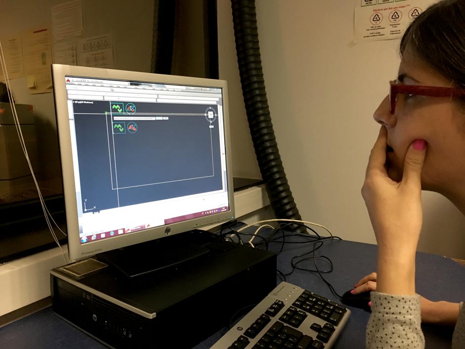
Marta and I started to try use the machine with the same file as Silhouete, our own logo. To save time, I explained to Martha the use of the machine and cut both files at once.
|
Marta working with Autocad
|
|
Autocad`s work space
|
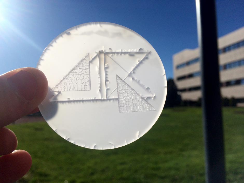
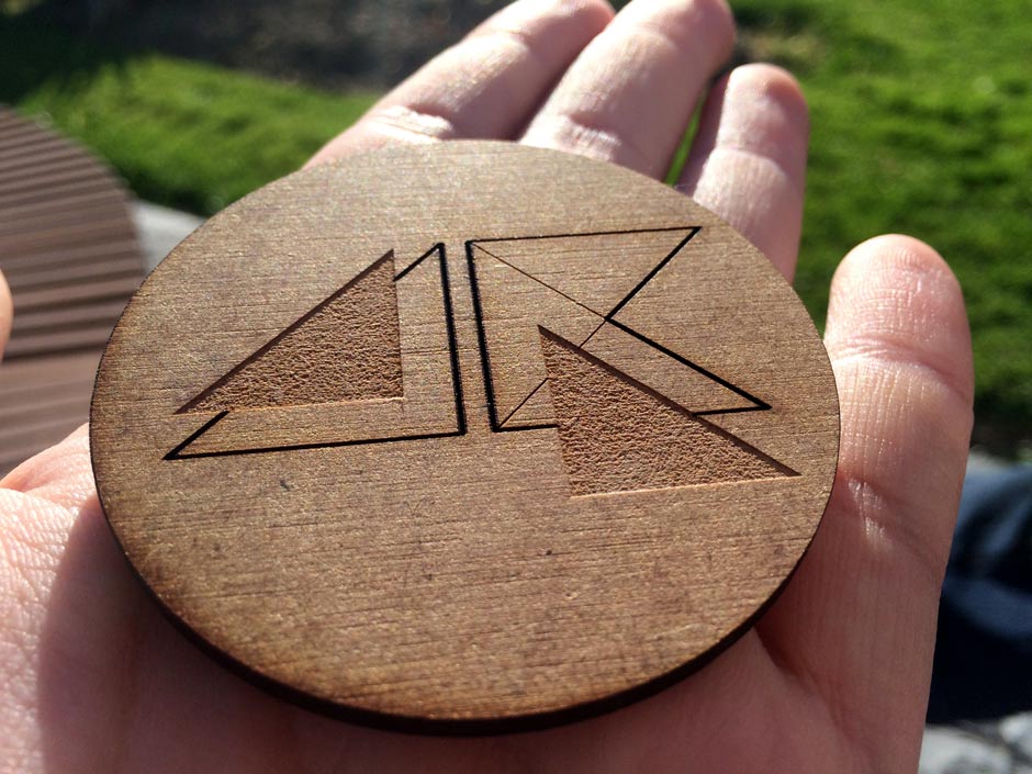
First we tested with methacrilate and dm wood. I have used interior cut, exterior cut, engraving for some lines and raster engraving for the triangles.
Results
|
|
|
|
|
|
We made other testing pieces and the best one is 2.6mm.
|
Press fit piece
I started with week 2 assigment minimal surface. I worked with Grasshopper to find the form. Then I use a new grasshopper file to find the waffling. This is a parametric design because I can choose the quantity of lines (cuts) I will need, the intersection between pieces etc.
The process of the assigment is:
1) make the initial and final minimal surfaces. I generate them through grasshopper, more info in week 2 assigment.
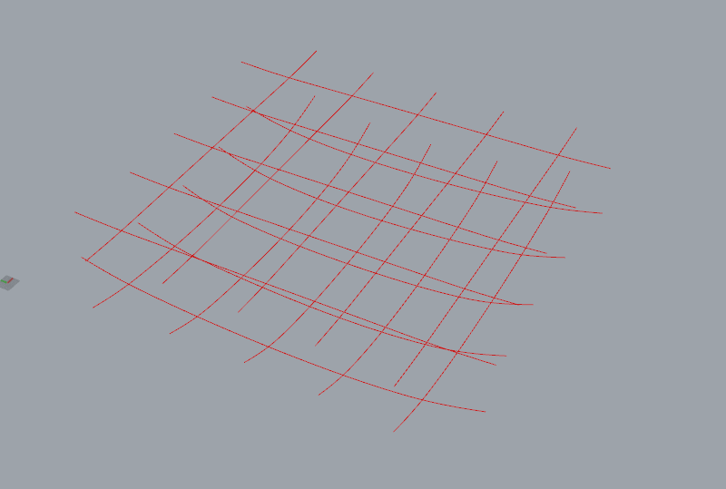
2)find the lines where I will cut the surface
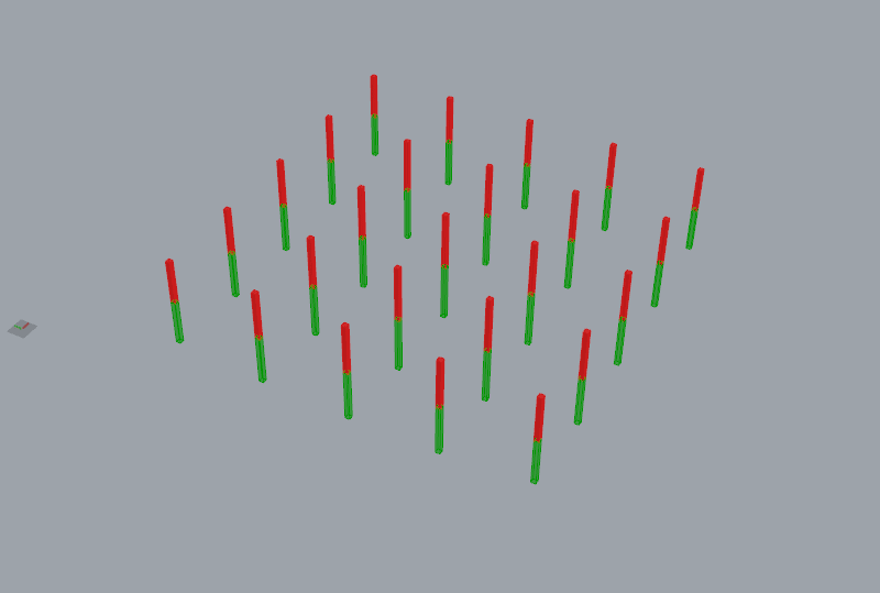
3)extrude these lines to find the intersection between them, make another extrusion from surfaces to find the intersection between extrusions. This is the most important point, because we will get the matches between the boards. They are at the midpoint between the initial and final surface.
4)get the lines of the pieces, map to the xy plane, also add the names of the pieces to be cut to know their order.
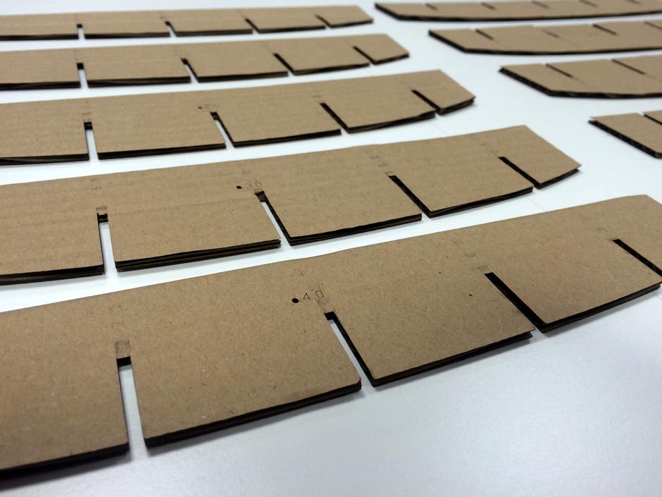
5)cut the cardboard in the laser cutter.
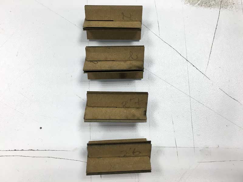
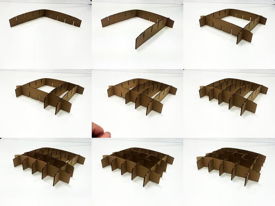
6)assemble the pieces
6)it's done!
For the week 7 assigment I make other wafling with Grasshopper, a little more complicated, but works better than this.
|
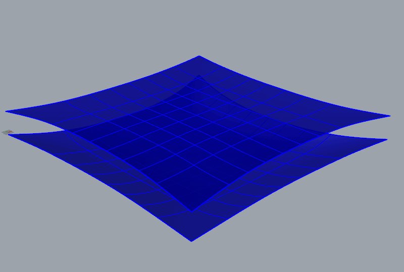
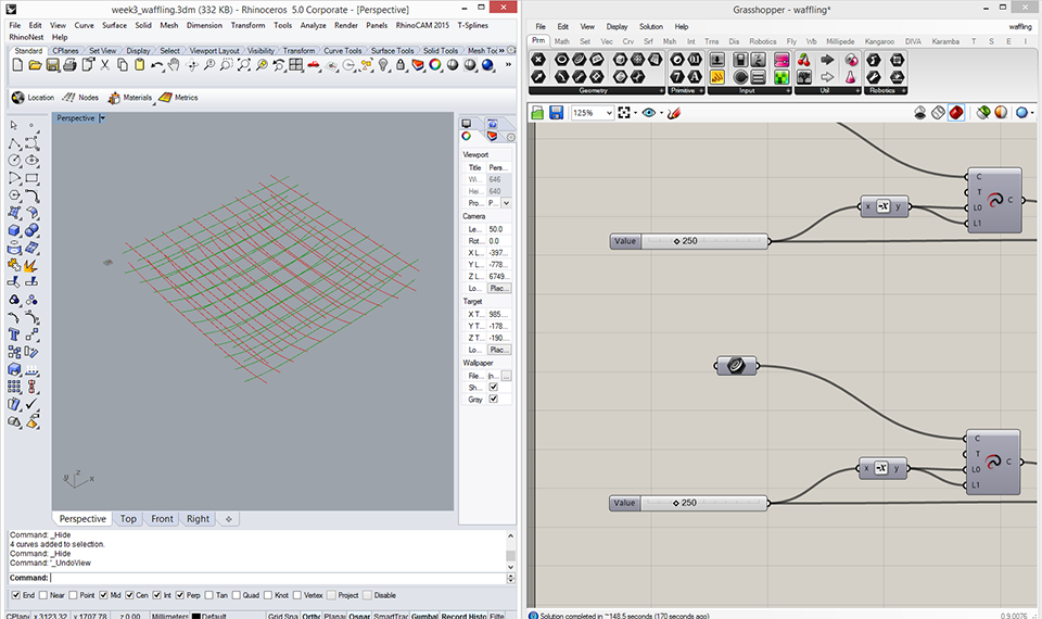
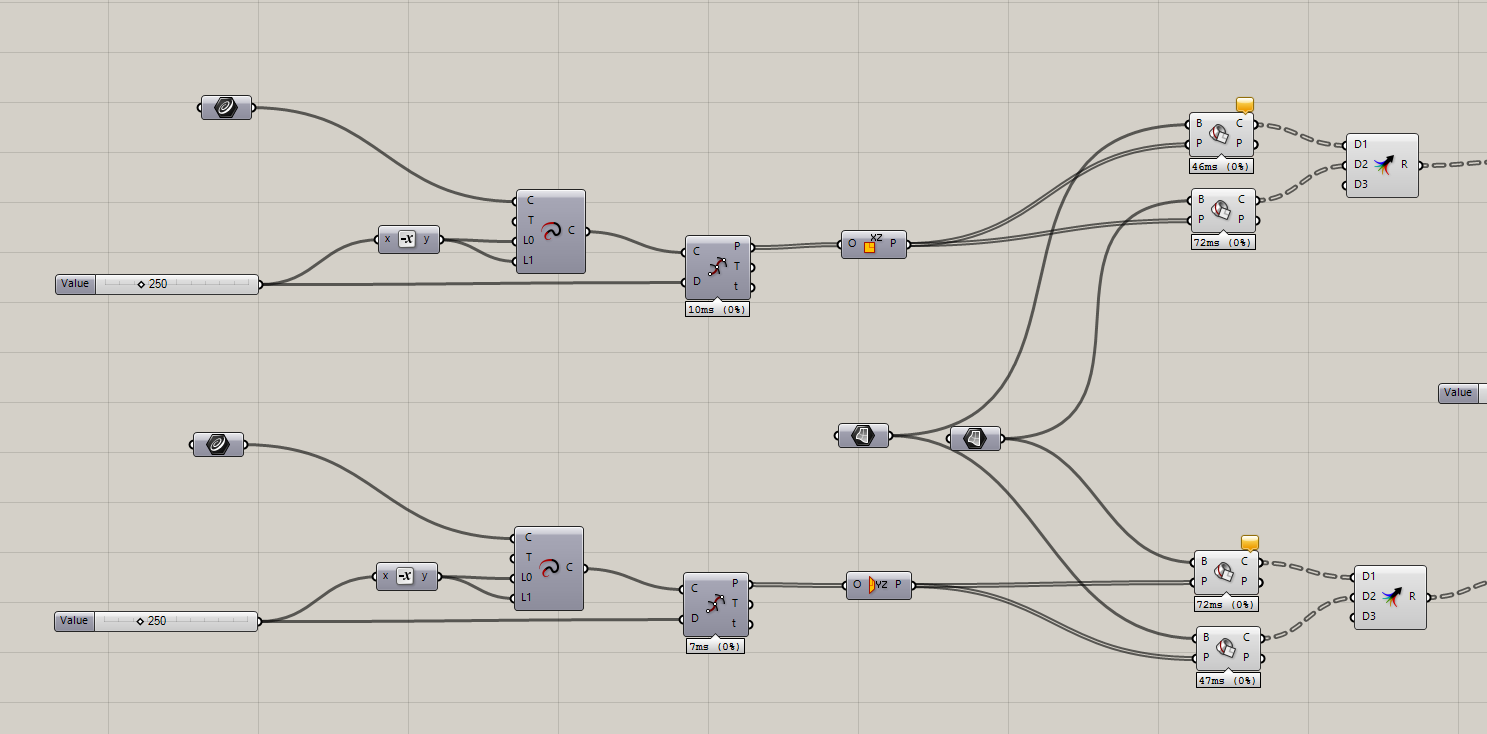
Transverse and longitudinal lines were made to find where I want the pieces to be, these are the sectioned lines. Then I loft these lines between the initial and final surface from the beginning.
|
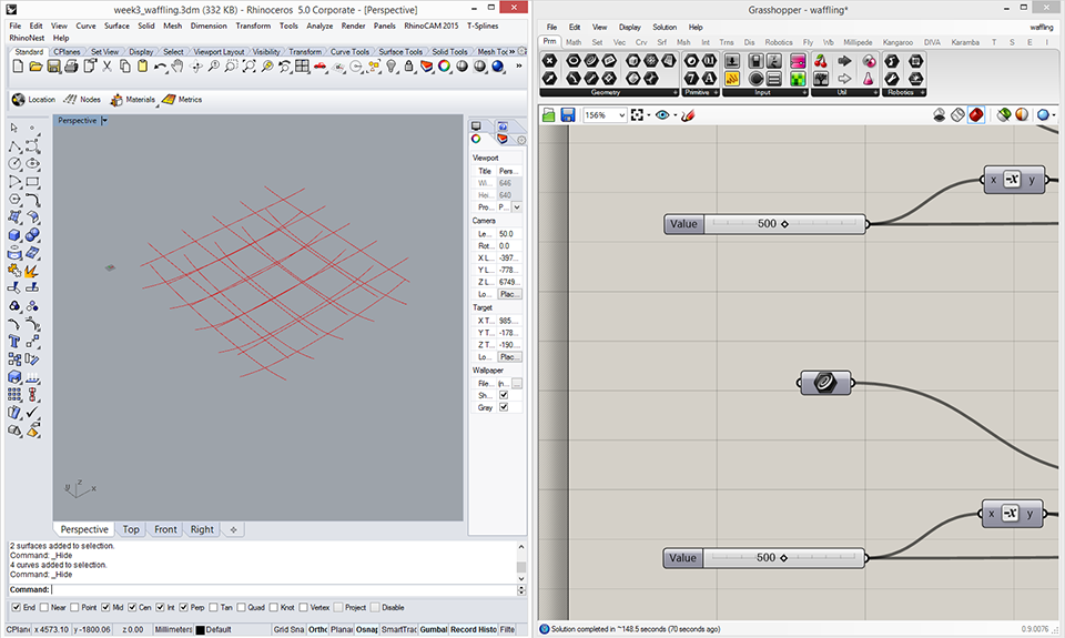
I can choose the distance between the lines. In the result I use 500. But I can proove with 250 and see the surface generated. I choose 500 because is a good proportion and doesn't have errors.
In this image I choose 250 the distance between the cut lines.
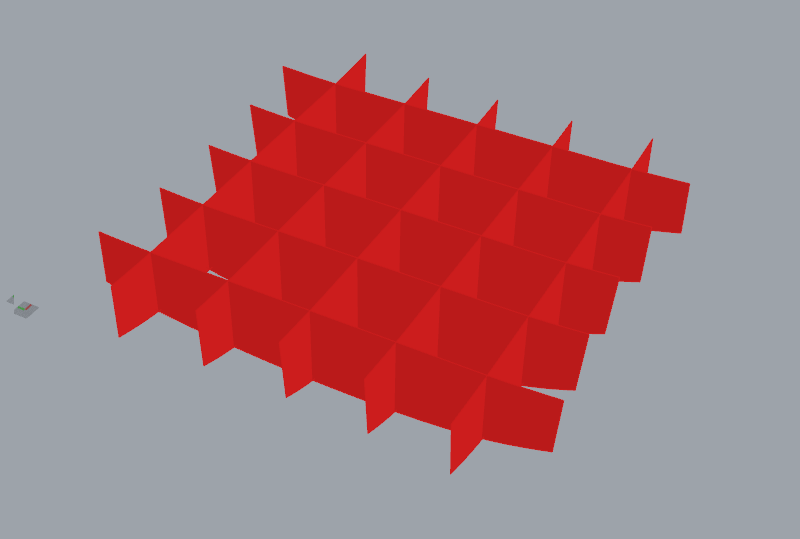
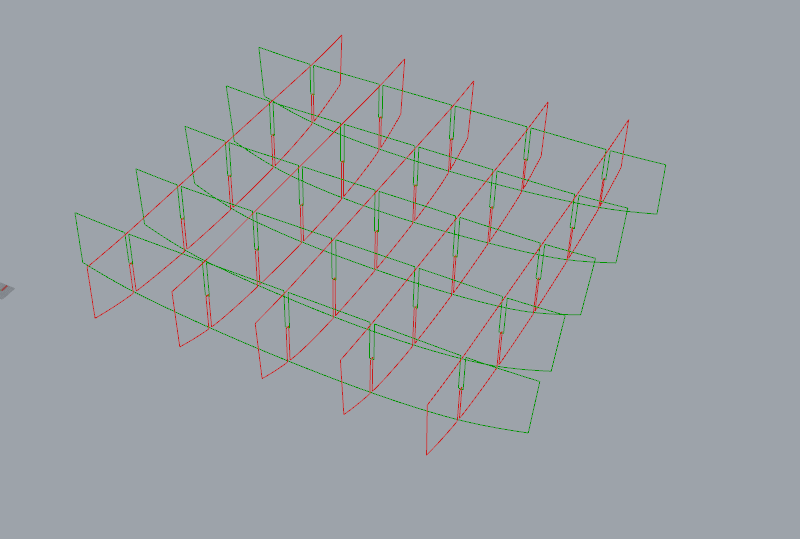
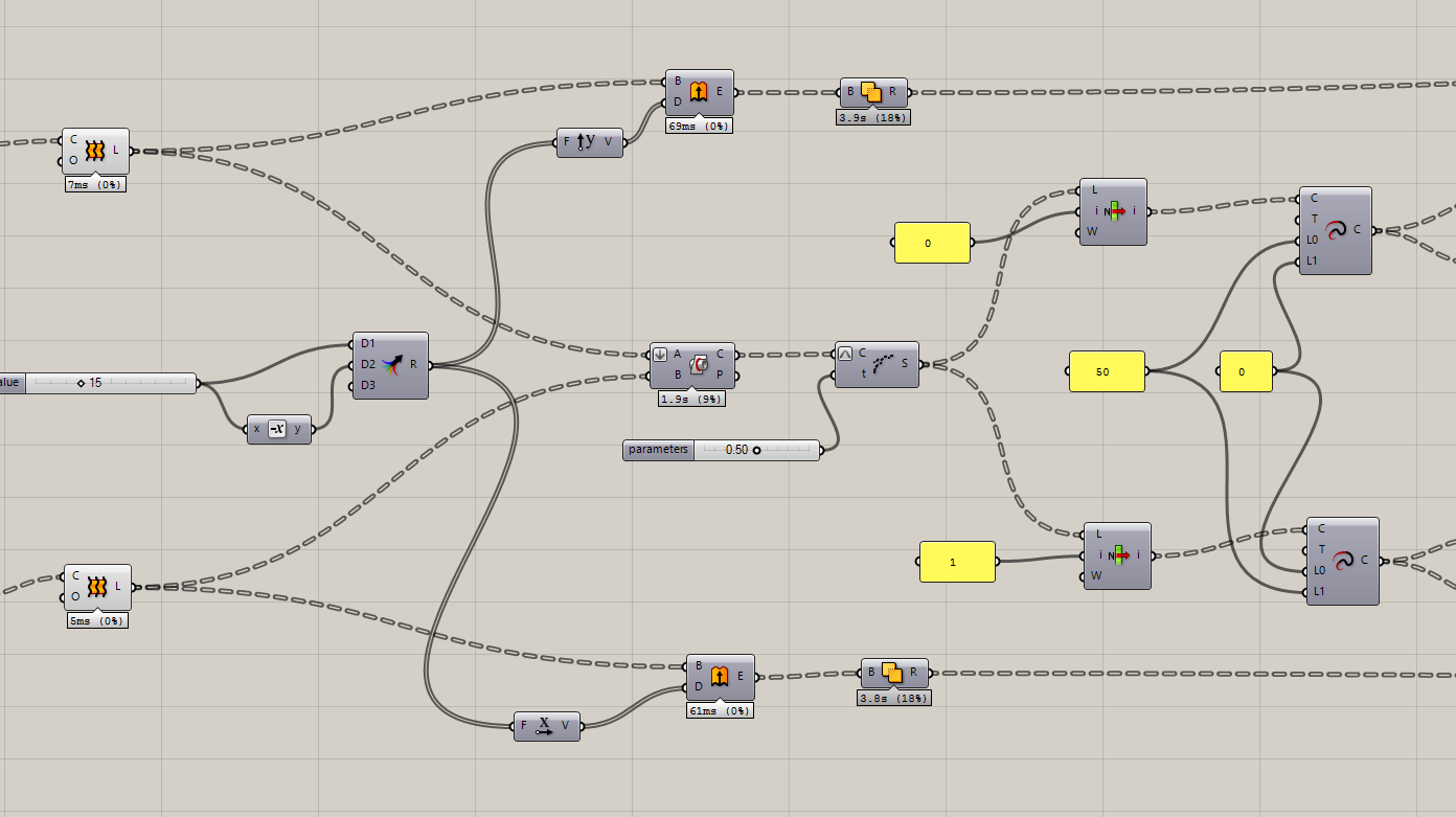
First convert the lines to surfaces, then extruded surfaces to find the intersections between extrusions. I made the interesections between the pieces at the midpoint to have better fit pressed piece.
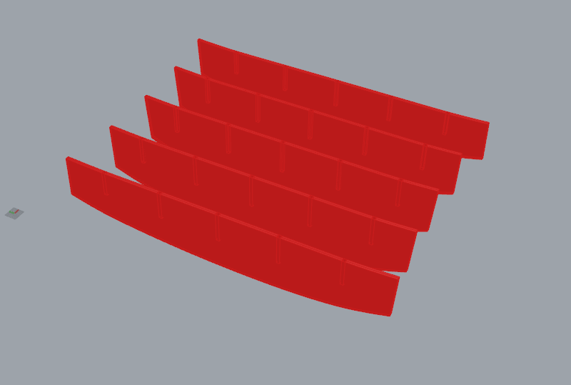
This is the surfaces result using 250 as distance between the lines.
This is the boolean between the extruded shapes. There is at 50% between the first and the second extrusion.
|
|
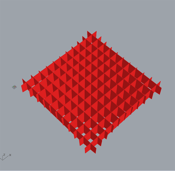
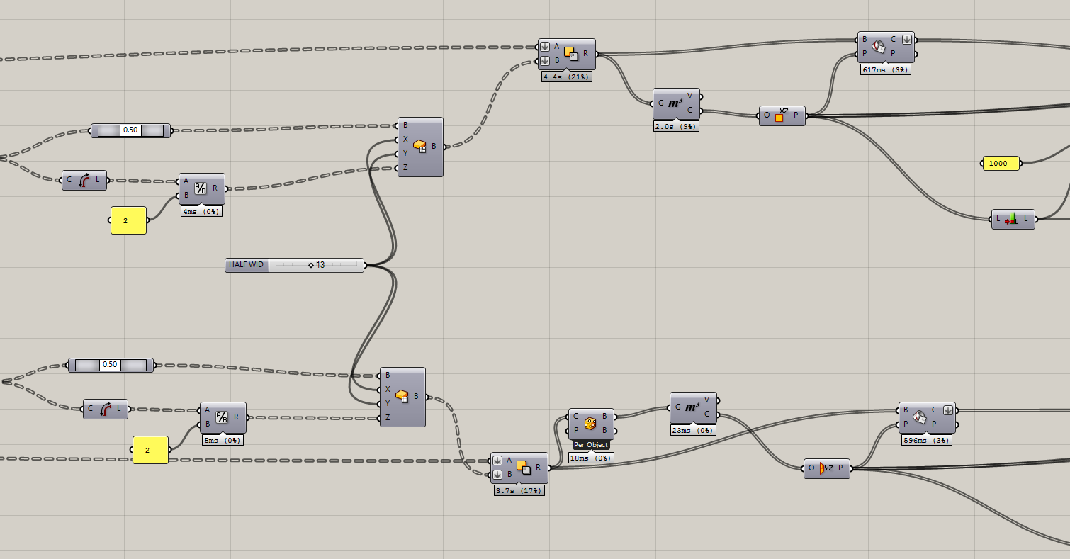
Then I make a boolean to get the final pieces.
|
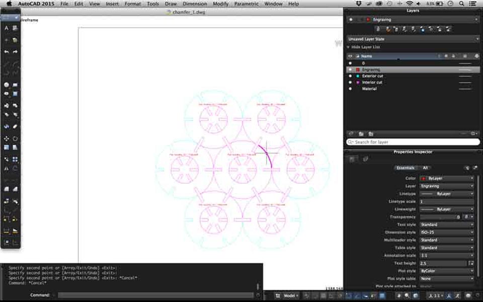
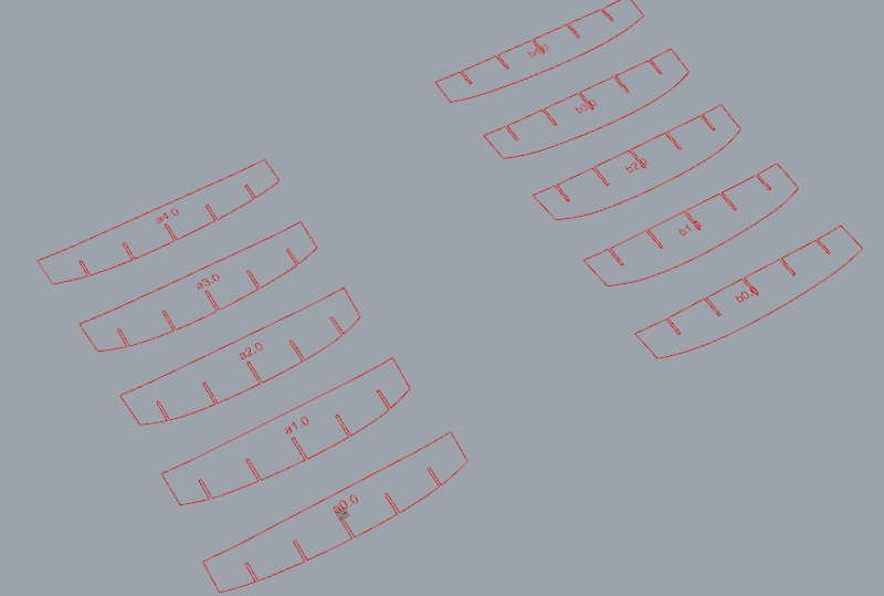
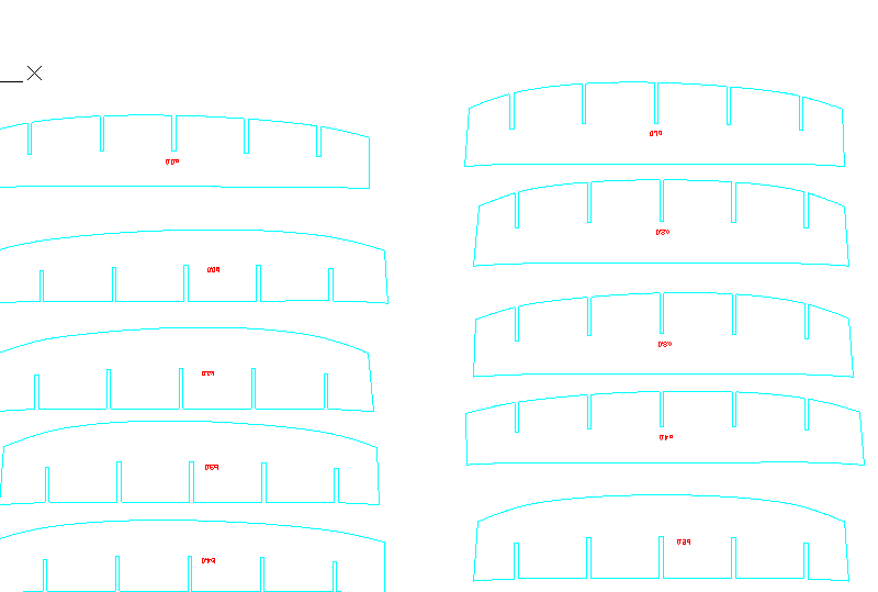
When I get the pieces I rotate and flatten all pieces. The pieces were named and ordered to be released.
There are the pieces to cut.
|
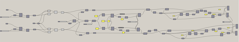
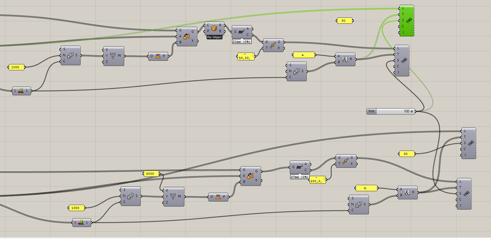
I used Grasshopper because it is a parametric program that lets me choose distances and joints and change according to my needs. This is the definition and some zooms:
In this capture, I choose the intersection between both surfaces.
|
|
|
|
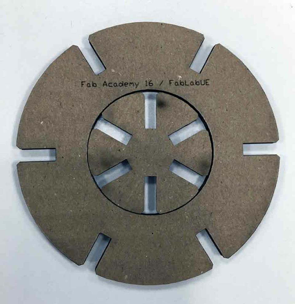
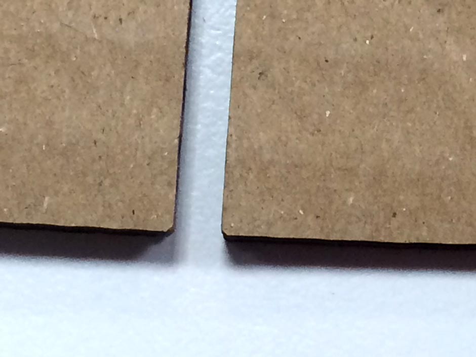
tiny chamfers
|
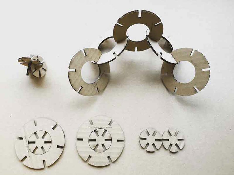
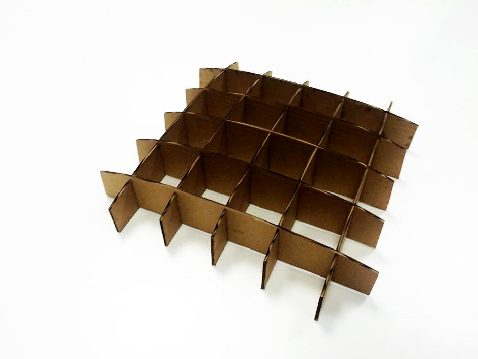
Asdembly process
|
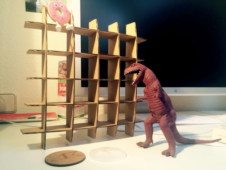
FINAL RESULT
COMPUTER-CONTROLLED CUTTING |
|
Explained how you drew your files |
x |
Shown how you made your press-fit kit |
x |
Included your design files and photos of your finished project |
x |
Vinyl Cutting - Explained how you drew your files |
x |
Vinyl Cutting - Shown how you made your vinyl project |
x |
Vinyl Cutting - Included your design files and photos of your finished project |
x |
rhino + grasshopper file
waffling autocad file