THE PROGRAMMING
I2C Networking
Master Programming
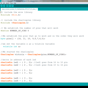
Slave Programming
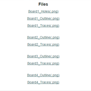
THE FILES
Structure
Acrilyc
Holding pieces
The boards
Arduino
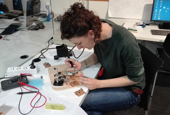
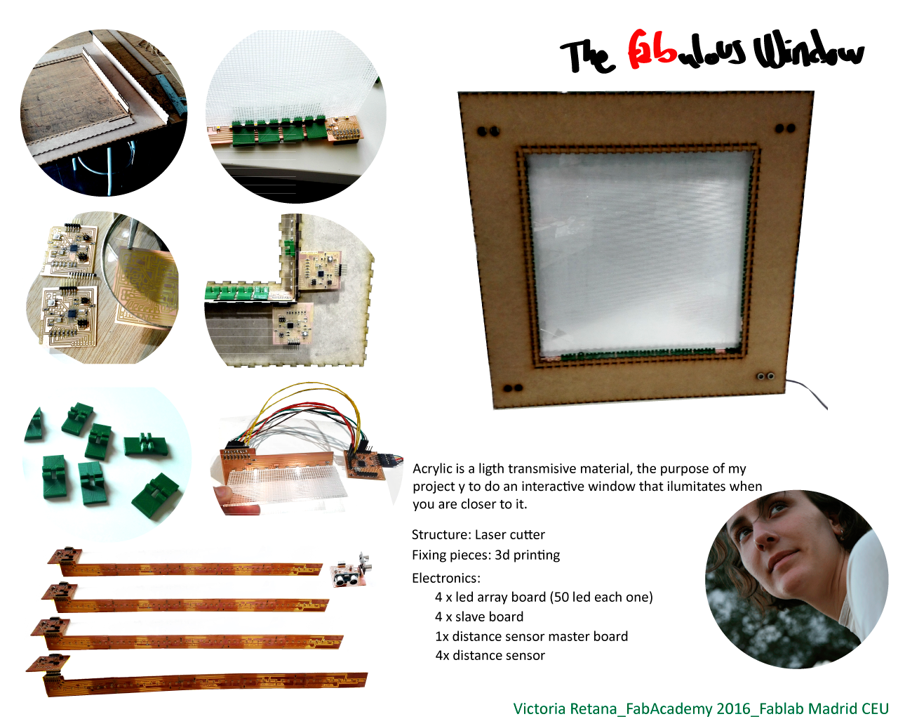
The idea of my final Academy project is to accomplish my architecture final project. I wanted to do an interactive façade, so I decided to do a module of it, an interactive window with distance sensors as input.
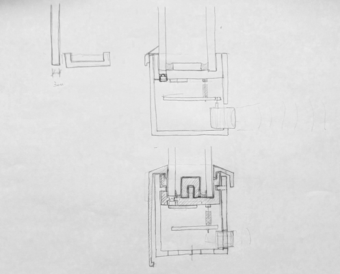
As long I was working in the idea of the interactive window I consider different options as two acrylic layers, the holding system, of where should I put the distance sensor.
Finally I decided to integrate the whole project inside the structure and I decided use just a single acrylic layer to have a nicer effect. I made several holes for the distance sensor so as I will connect it with wires I can put it where I want.
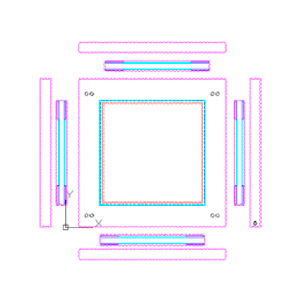
For the computer aided 2d design class I explained how I draw my final structure plans. (computer-aided design 2d)
I decided to do the structure of my final project using Autocad. As later I will cut the file with the laser cutter I will take in count some parameters.
The first thing I do, is to open a dwg template:
- File _ New _Template
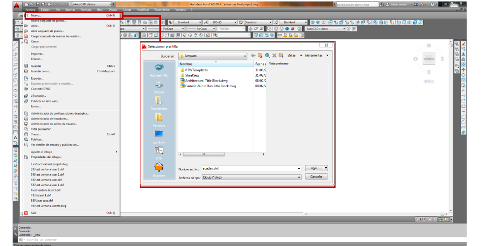
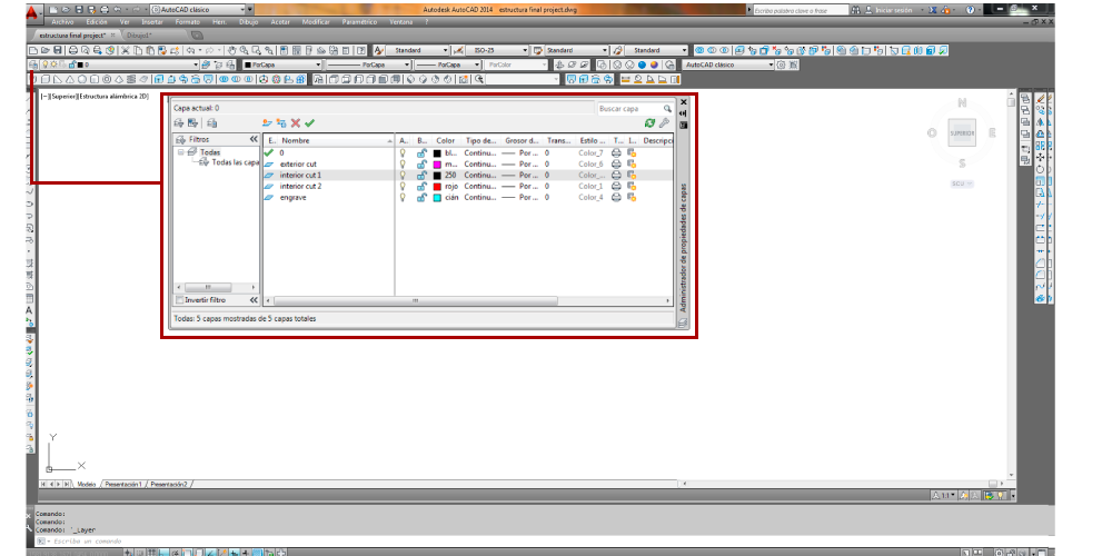
Autocad lets you to manage several layers and each of them can have different properties. As I will use the file with the laser cutter machine I did different layers and I gave them different colors because the laser cutter machine that we have in our fab lab identify the colors as layers. So I divide the layers Knowing the cutting order and the cutting properties:
- Interior cut 1
- Interior cut 2
- Interior cut 3
- Exterior cut
- Engraving
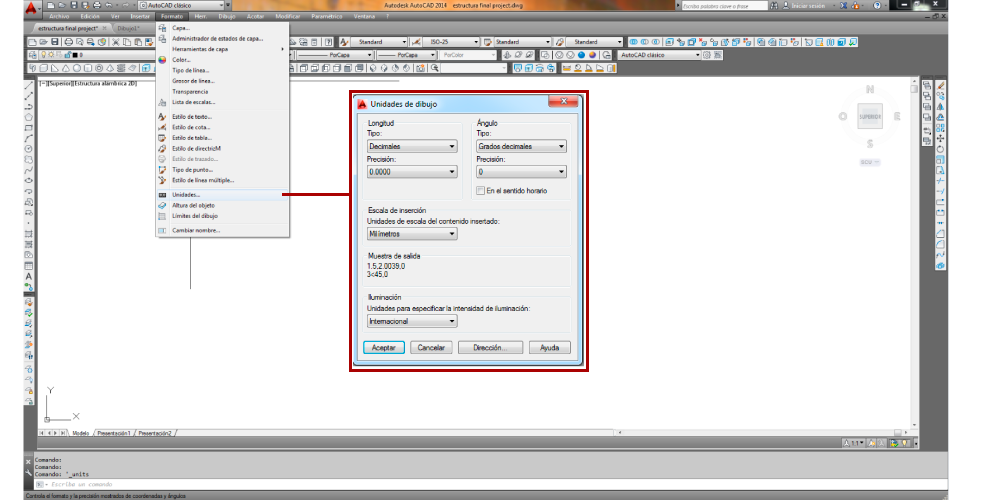
I also needed that the units were in millimeters so:
- Format _ Units _ Millimeters
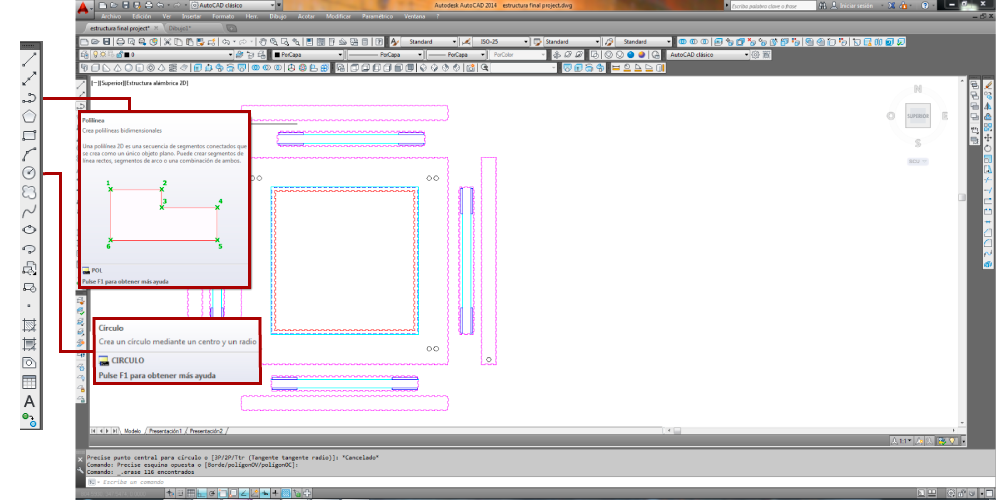
The basic tools that I used to draw the file were polyline and circle tools.
The difference between line and polyline is that the polyline it can have a shape and it can be closed, I did this to be sure that with the laser cutter will do it in order.
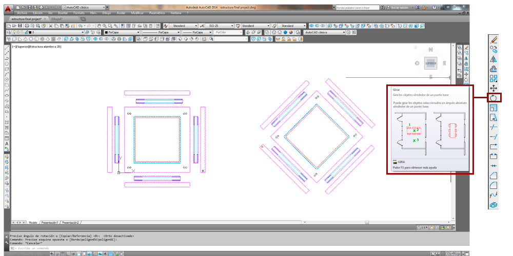
Another toolbar allows you to change what you've already drawn.
You can Copy polyline or a group of them.
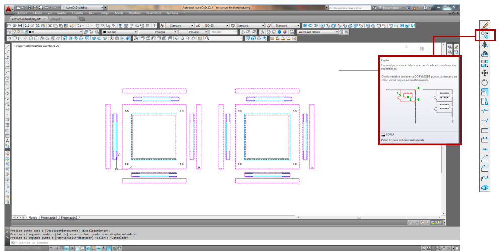
You can also rotate, scale or symmetry.
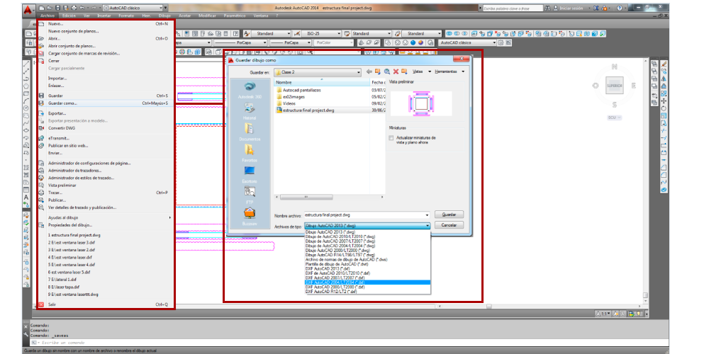
Autocad lets you to save the file in different formats I chose dxf 2004 because this is the format file for the laser cut program.
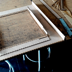
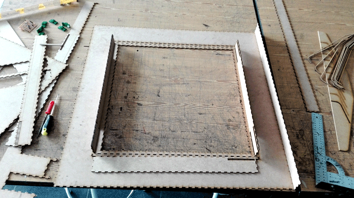
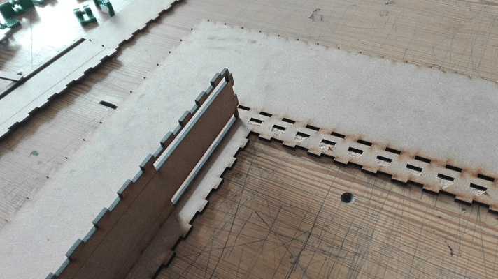
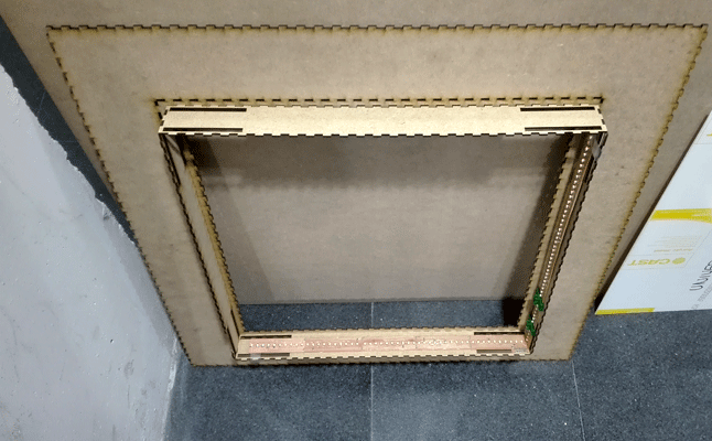
The structure
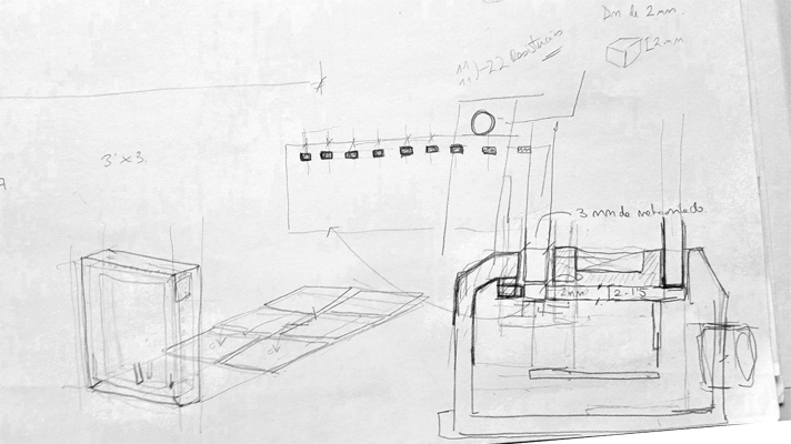
The structure is made by MDF boards cut with the laser cutter. I did a press-fit structure, I draw the file in Autocad to cut it later in the laser cutter machine, so some things that I had to consider were:
- The tolerances: cutting 3mm MDF Boards one piece has to be 0,1 mm bigger than the other because of the material that is lost cutting the piece.
- The laser cutter machine recognize the colors as layers so I did 2 layers in Autocad with different colors in order to set them in order , first I cut the interior cut and then the exterior, if wanted to do an engrave layer I would give it a different color and different cutting properties.
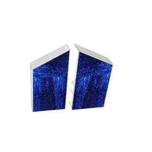
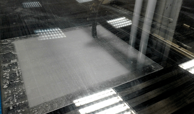
Acrylic
For the acrylic engraving despite having the same properties cutting I did two layers, one for the vertical lines an the other for the horizontal the reason to do that was that the machine will spend cutting without order, but once I cut it I realized that some parts were bend because the lines that I draw were too close to each other and I should have done more layers and send them separately to cool the acrylic and avoid bending the acrylic.
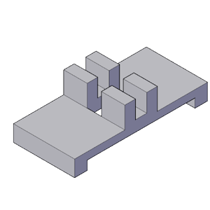
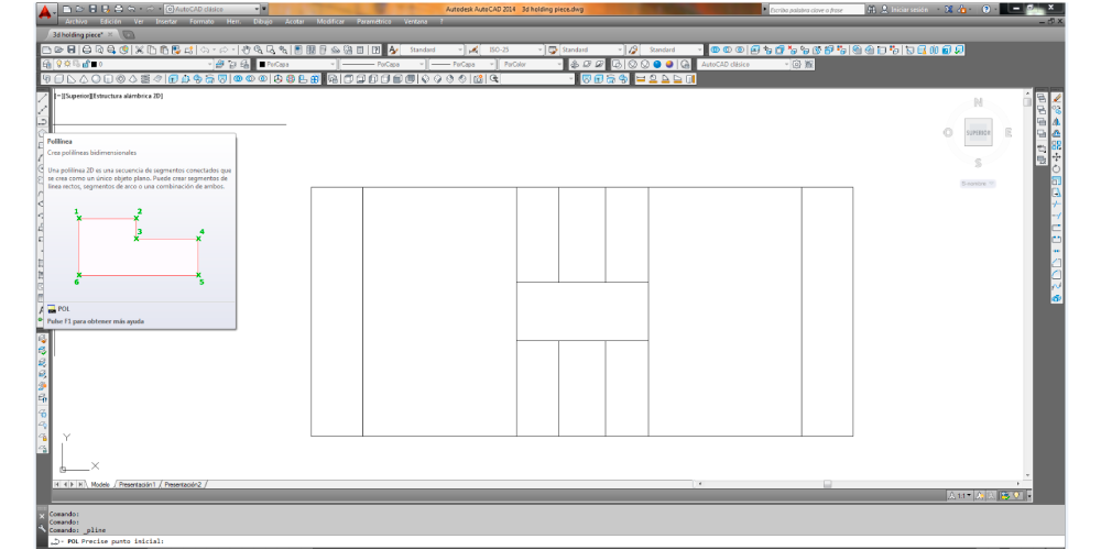
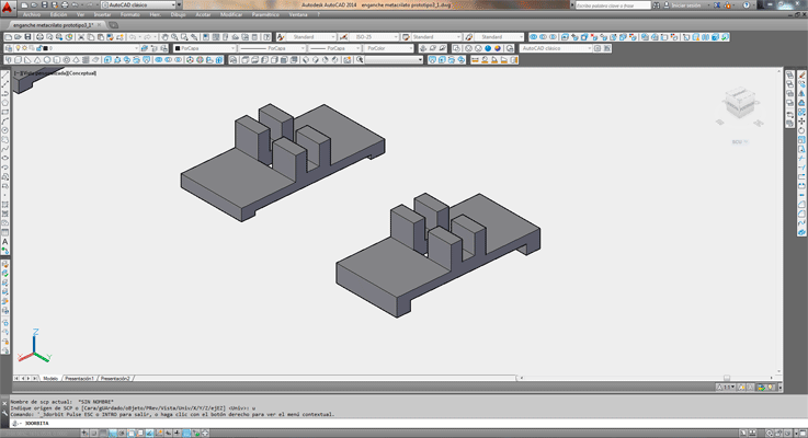
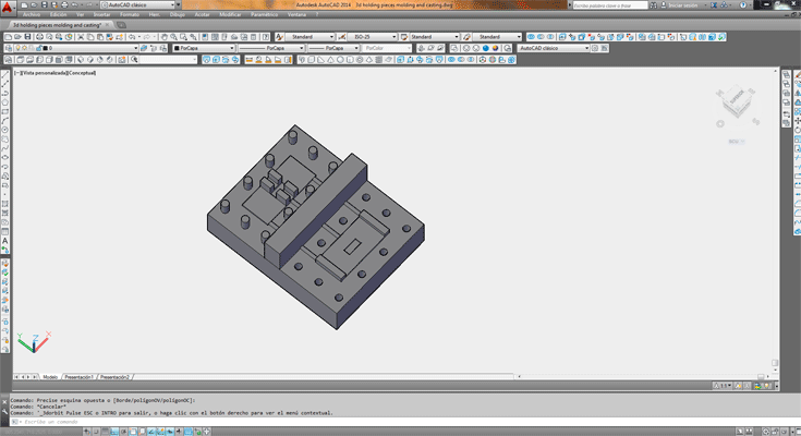
For the computer aided 3d design class I explained how I draw my final holding pieces. (computer-aided design 3d)
I draw the holding pieces of my final project with Autocad.
The first thing I did was to draw in 2d the plan of the piece using the drawing tool polyline.
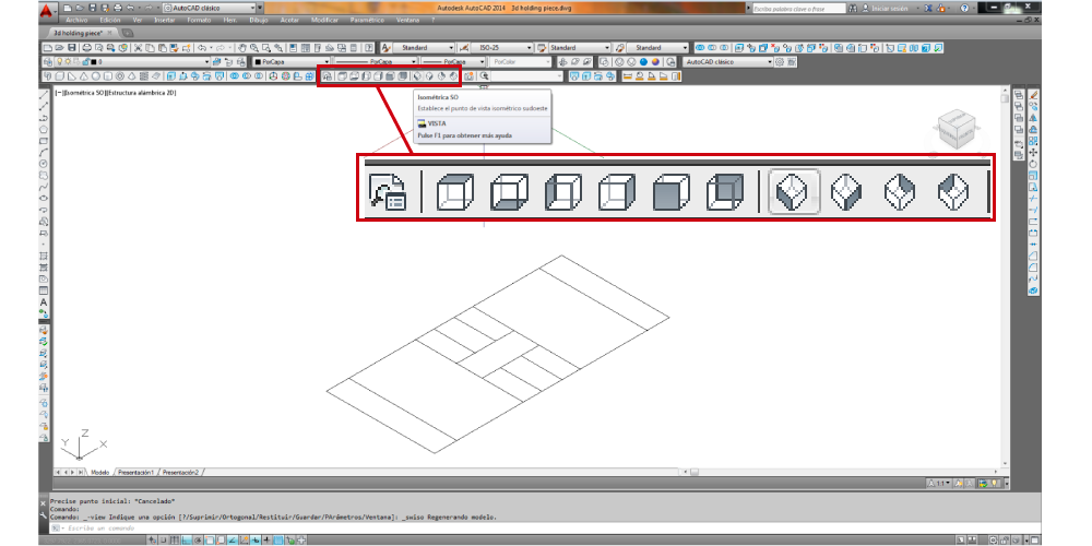
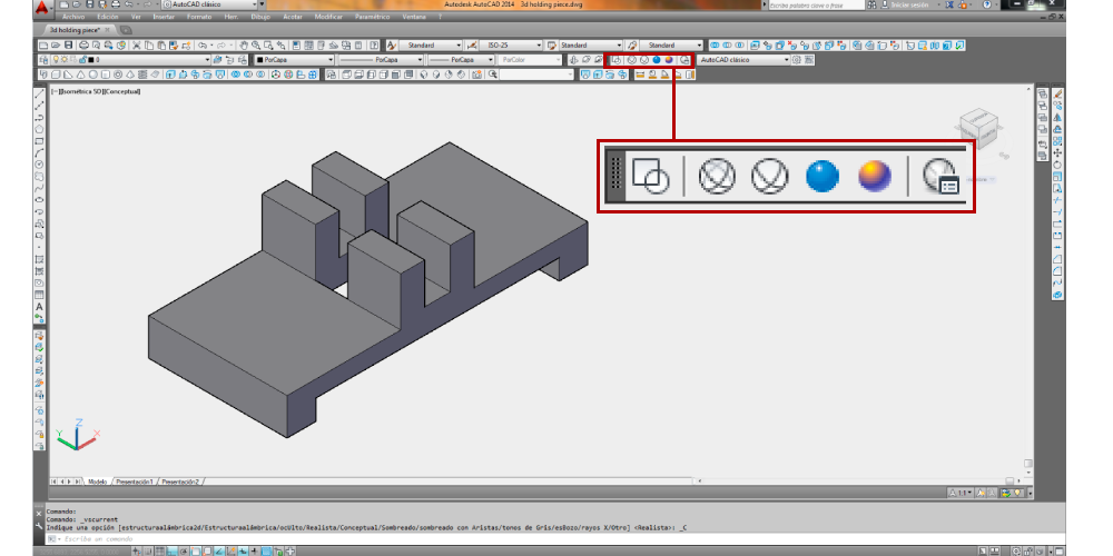
To draw something in 3d the first thing that you have to do is to choose the view.
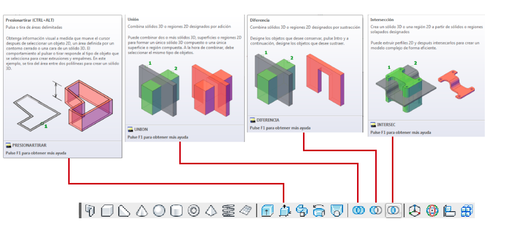
One of the 3d toolbars of Autocad lets you some 3d options as extrude, push pull, loft or make shapes as spheres or prisms.
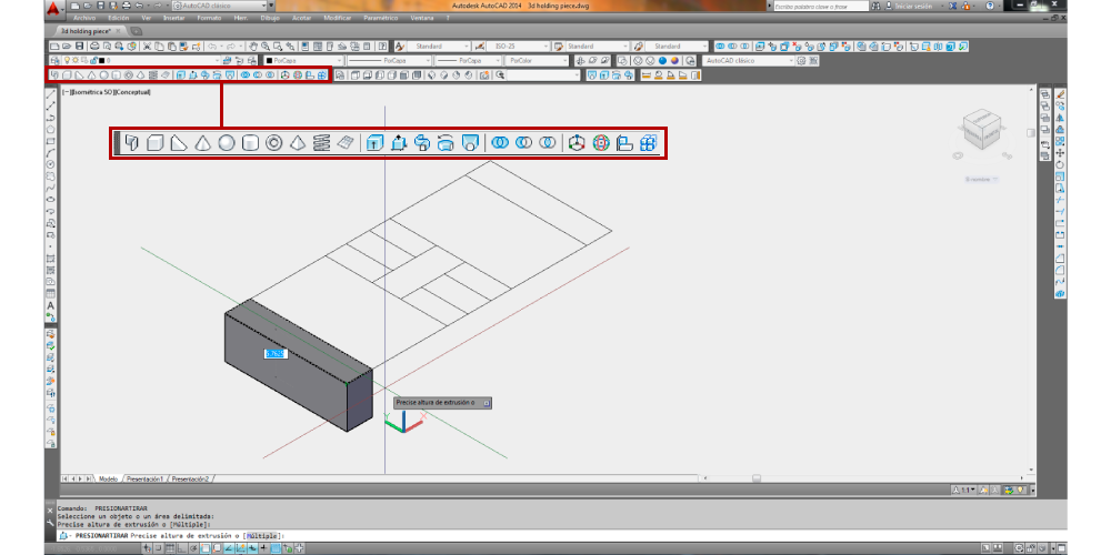
If you have different solids you can unite, subtract or make the intersection of them.
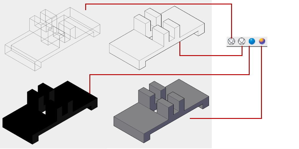
You can also choose the view options wired, solid, realistic or conceptual.
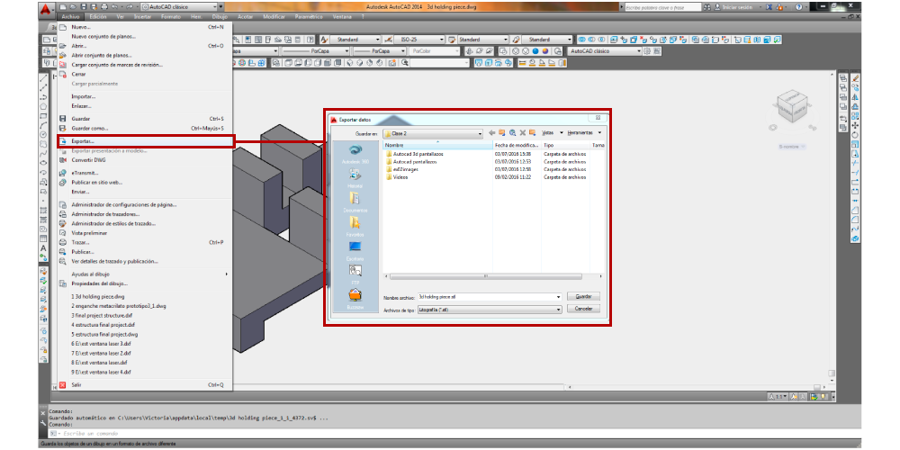
Autocad let you save the file in many formats but as I wanted the file for the 3d printer machine I needed it as stl, so I exported the file as stl:
- File_ Export _ stl
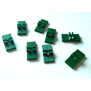
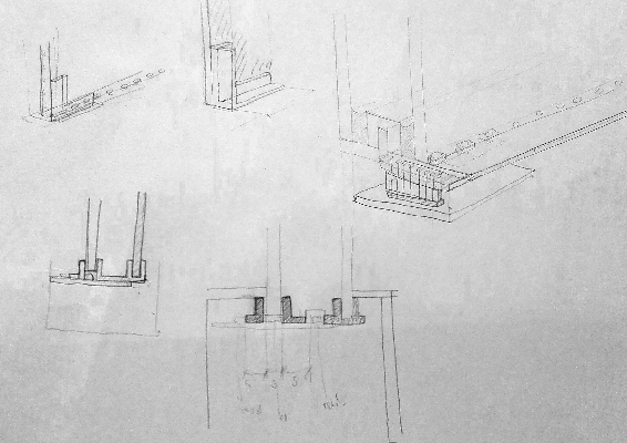
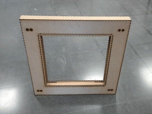
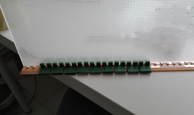
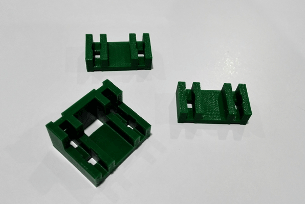
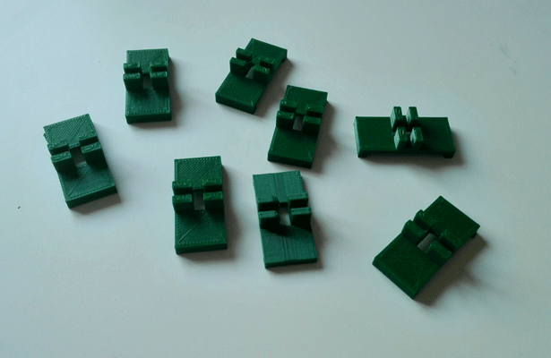
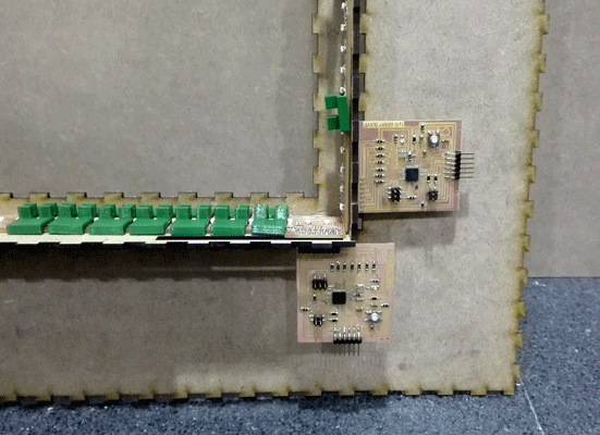
Holding pieces
To hold the acrylic I design a piece to be between the leds and the acrylic.
I draw the file in Autocad, and I printed it with the MakerBot Replicator 2 using green 1,75 mm diameter PLA. To print the pieces I had to export the file in STL.
I did a lot of test to find the perfect tolerance to hold the acrylic. At the beginning I was thinking about doing a double acrylic window but I change my mind I because I thought that it would be a nicer effect if I just do an acrylic board illuminate from the four edges.
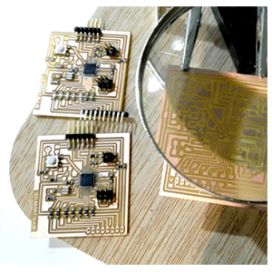
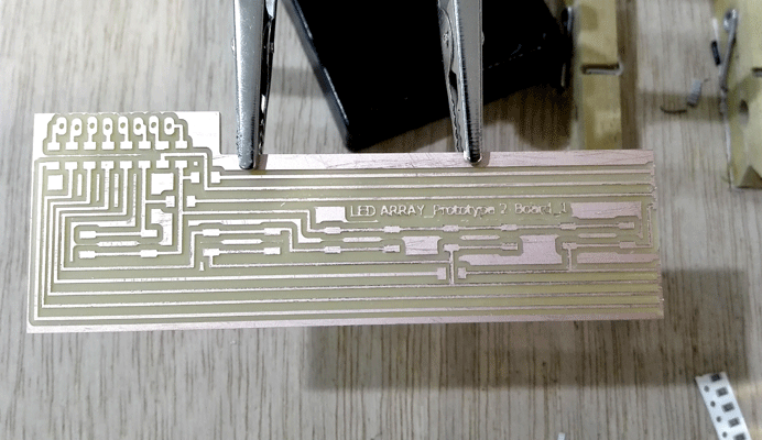
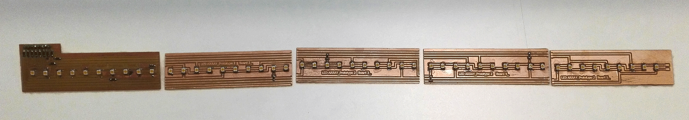
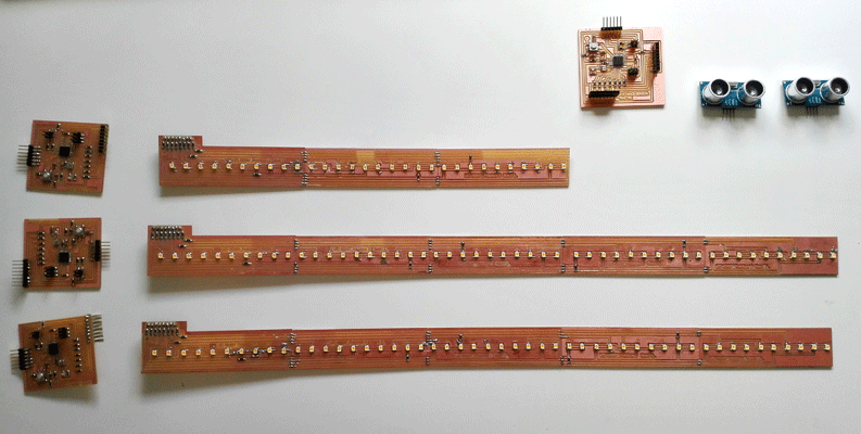
LED array board
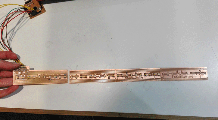
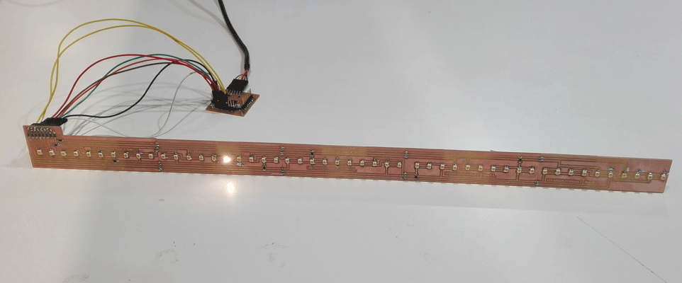
The first thing I did was to understand really haw the charlieplex work , so I design a 50 LEDs array board made by 5 boards connected with a little bit of tin, I had to divide the board in 5 because of the size of the Rolland mill and the size of the boards.
The complete led array board is 50cm long and 3 cm width.
To test if the board was correctly design I used the fabkit board that I did in a week assignment to see if it worked, as it worked, I did the other three boards.

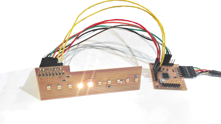
prototype 2_test 3 from vretana on Vimeo.
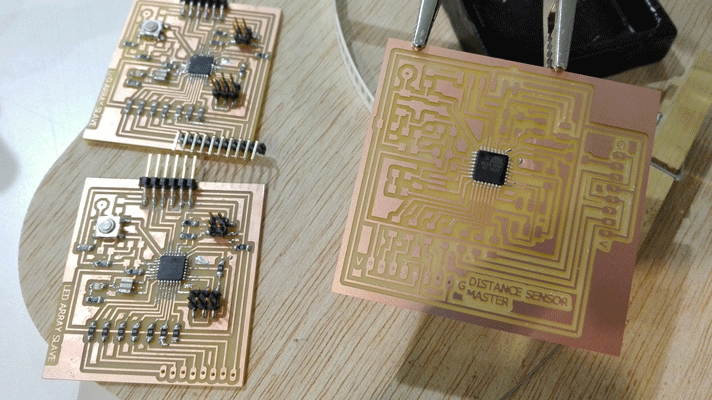
The slave and master boards
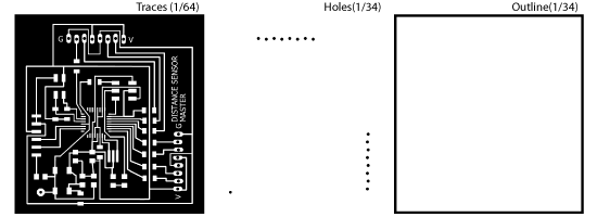
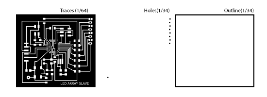
I did the master and the slave board using the Atmel mega 168A microcontroller.
The slave board had 8 head to connect with the led array board.
The master has space to connect up to four distance sensors but for the project I just connect one.
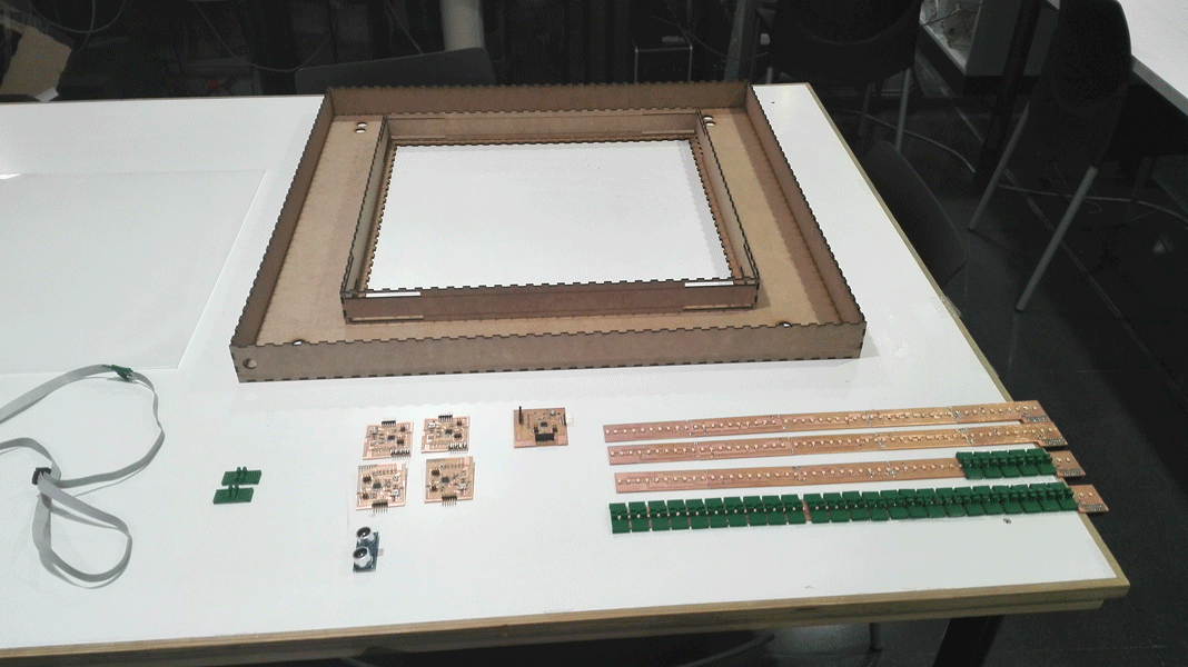
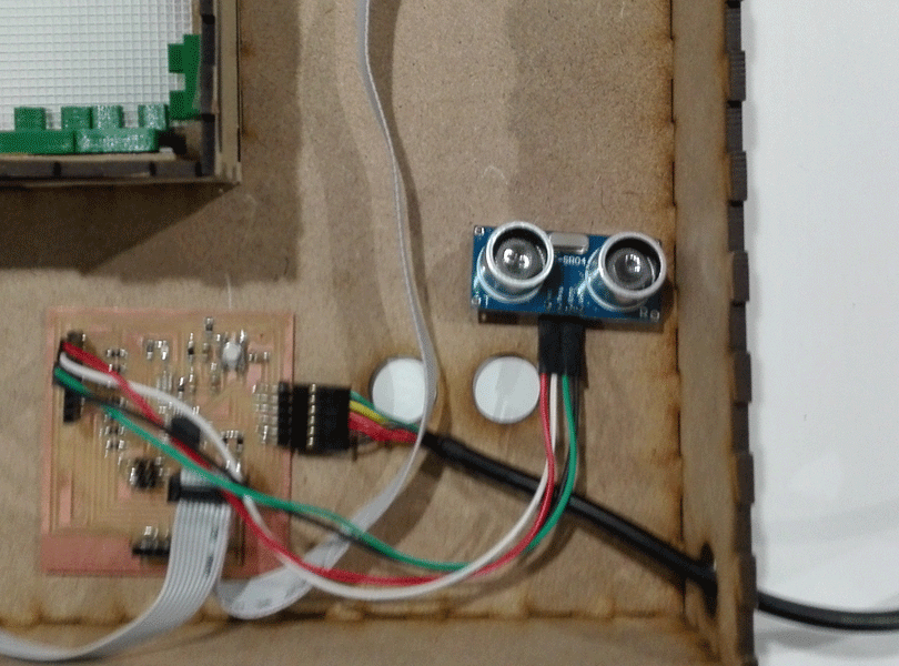
The input
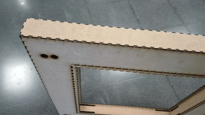
The input that I used was the distance sensor HC-SR04. The master board has space to connect up to four distance sensors but for the project I just connect one. And I connect it using wires, I did several holes in the MDF structure in order to put the sensor anywhere you want.
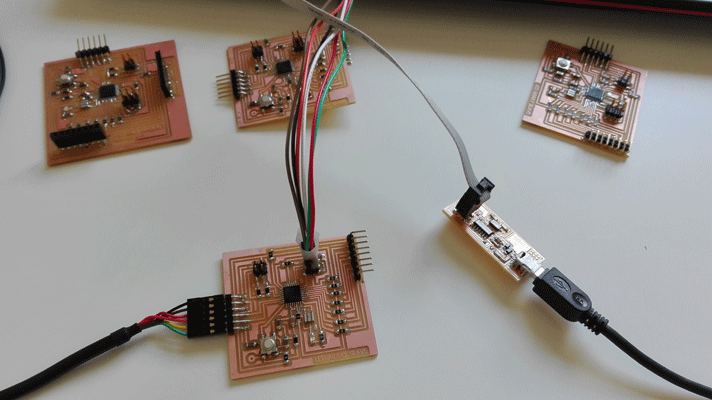
For the networking and communications assignment I did the networking of my final project (networking and communications)
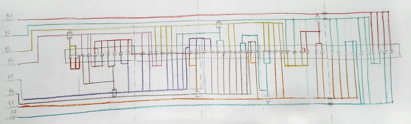
To connect the boards I used I2C communication being the master the distance sensor board and the slaves the four boards that are connected to the led array board.
The Charlieplex works using two pins, by a pin enters the supply and on the other leaves so using two pins we could turn on the LEDs independently by changing the direction of one of them because the LEDs are diodes.
To turn on 50 LEDs I needed at least eight pins and by making combinations of them I gave them different addresses.
The addresses of the pins start from 0. So if I used 8 pins the addresses of them are 0,1,2,3,4,5,6,7.
// Slave programming // include the wire library #include// include the charlieplex library #include // We establish the number of pins that will work #define NUMBER_OF_PINS 8 //We establish the pins that go to work and in the order they will work byte pins[] = {16, 11, 10, 9,8,7,6,5}; //we set the variable x as a volatile variable volatile int x; //We started the charlieplex Charlieplex victoria = Charlieplex(pins,NUMBER_OF_PINS); //write le address of each led charliePin led1 = { 0 , 2}; //led1 goes from 16 to 10 pin charliePin led2 = { 2 , 0}; //led1 goes from 10 to 16 pin charliePin led3 = { 5 , 3}; charliePin led4 = { 3 , 5}; charliePin led5 = { 3 , 0}; charliePin led6 = { 0 , 3}; charliePin led7 = { 5 , 0}; charliePin led8 = { 0 , 5}; charliePin led9 = { 4 , 0}; charliePin led10 = { 0 , 4}; charliePin led11 = { 4 , 3}; charliePin led12 = { 3 , 4}; charliePin led13 = { 3 , 2}; charliePin led14 = { 2 , 3}; charliePin led15 = { 4 , 2}; charliePin led16 = { 2 , 4}; charliePin led17 = { 4 , 1}; charliePin led18 = { 1 , 4}; charliePin led19 = { 6 , 4}; charliePin led20 = { 4 , 6}; charliePin led21 = { 5 , 4}; charliePin led22 = { 4 , 5}; charliePin led23 = { 5 , 1}; charliePin led24 = { 1 , 5}; charliePin led25 = { 5 , 2}; charliePin led26 = { 2 , 5}; charliePin led27 = { 5 , 7}; charliePin led28 = { 7 , 5}; charliePin led29 = { 6 , 5}; charliePin led30 = { 5 , 6}; charliePin led31 = { 7 , 2}; charliePin led32 = { 2 , 7}; charliePin led33 = { 6 , 2}; charliePin led34 = { 2 , 6}; charliePin led35 = { 2 , 1}; charliePin led36 = { 1 , 2}; charliePin led37 = { 2 , 0}; charliePin led38 = { 0 , 2}; charliePin led39 = { 6 , 0}; charliePin led40 = { 0 , 6}; charliePin led41 = { 6 , 1}; charliePin led42 = { 1 , 6}; charliePin led43 = { 6 , 7}; charliePin led44 = { 7 , 6}; charliePin led45 = { 7 , 1}; charliePin led46 = { 1 , 7}; charliePin led47 = { 1 , 0}; charliePin led48 = { 0 , 1}; charliePin led49 = { 7 , 0}; charliePin led50 = { 0 , 7}; boolean singleOn = false; void setup() { Wire.begin(2); // we start i2c communication and we call this slave 2 Wire.onReceive(receiveEvent); // the slave is receiving information Serial.begin(9600); // we set the communication by the serial port and the communication speed pinMode (13,OUTPUT); // we set the pin 13 as output } void loop() {if (x==1){ // if x = 1, the LEDs are lit, and clean all the information each time we change led if (singleOn){ victoria.clear(); } victoria.charlieWrite(led1,HIGH); delay(100); victoria.clear(); victoria.charlieWrite(led2,HIGH); delay(100); victoria.clear(); victoria.charlieWrite(led3,HIGH); delay(100); victoria.clear(); victoria.charlieWrite(led4,HIGH); delay(100); victoria.clear(); victoria.charlieWrite(led5,HIGH); delay(100); victoria.clear(); victoria.charlieWrite(led6,HIGH); delay(100); victoria.clear(); victoria.charlieWrite(led7,HIGH); delay(100); victoria.clear(); victoria.charlieWrite(led8,HIGH); delay(100); victoria.clear(); victoria.charlieWrite(led9,HIGH); delay(100); victoria.clear(); victoria.charlieWrite(led10,HIGH); delay(100); victoria.clear(); victoria.charlieWrite(led11,HIGH); delay(100); victoria.clear(); victoria.charlieWrite(led12,HIGH); delay(100); victoria.clear(); victoria.charlieWrite(led13,HIGH); delay(100); victoria.clear(); victoria.charlieWrite(led14,HIGH); delay(100); victoria.clear(); victoria.charlieWrite(led15,HIGH); delay(100); victoria.clear(); victoria.charlieWrite(led16,HIGH); delay(100); victoria.clear(); victoria.charlieWrite(led17,HIGH); delay(100); victoria.clear(); victoria.charlieWrite(led18,HIGH); delay(100); victoria.clear(); victoria.charlieWrite(led19,HIGH); delay(100); victoria.clear(); victoria.charlieWrite(led20,HIGH); delay(100); victoria.clear(); victoria.charlieWrite(led21,HIGH); delay(100); victoria.clear(); victoria.charlieWrite(led22,HIGH); delay(100); victoria.clear(); victoria.charlieWrite(led23,HIGH); delay(100); victoria.clear(); victoria.charlieWrite(led24,HIGH); delay(100); victoria.clear(); victoria.charlieWrite(led25,HIGH); delay(100); victoria.clear(); victoria.charlieWrite(led26,HIGH); delay(100); victoria.clear(); victoria.charlieWrite(led27,HIGH); delay(100); victoria.clear(); victoria.charlieWrite(led28,HIGH); delay(100); victoria.clear(); victoria.charlieWrite(led29,HIGH); delay(100); victoria.clear(); victoria.charlieWrite(led30,HIGH); delay(100); victoria.clear(); victoria.charlieWrite(led31,HIGH); delay(100); victoria.clear(); victoria.charlieWrite(led32,HIGH); delay(100); victoria.clear(); victoria.charlieWrite(led33,HIGH); delay(100); victoria.clear(); victoria.charlieWrite(led34,HIGH); delay(100); victoria.clear(); victoria.charlieWrite(led35,HIGH); delay(100); victoria.clear(); victoria.charlieWrite(led36,HIGH); delay(100); victoria.clear(); victoria.charlieWrite(led37,HIGH); delay(100); victoria.clear(); victoria.charlieWrite(led38,HIGH); delay(100); victoria.clear(); victoria.charlieWrite(led39,HIGH); delay(100); victoria.clear(); victoria.charlieWrite(led40,HIGH); delay(100); victoria.clear(); victoria.charlieWrite(led41,HIGH); delay(100); victoria.clear(); victoria.charlieWrite(led42,HIGH); delay(100); victoria.clear(); victoria.charlieWrite(led43,HIGH); delay(100); victoria.clear(); victoria.charlieWrite(led44,HIGH); delay(100); victoria.clear(); victoria.charlieWrite(led45,HIGH); delay(100); victoria.clear(); victoria.charlieWrite(led46,HIGH); delay(100); victoria.clear(); victoria.charlieWrite(led47,HIGH); delay(100); victoria.clear(); victoria.charlieWrite(led48,HIGH); delay(100); victoria.clear(); victoria.charlieWrite(led49,HIGH); delay(100); victoria.clear(); victoria.charlieWrite(led50,HIGH); delay(100); victoria.clear(); singleOn=!singleOn;} else{//if x is other than 1 LEDs are off victoria.clear(); } delay(100); } // function that runs whenever you receive something from the master void receiveEvent(int holaa) { // i2c communication we received x= Wire.read ();// we read by i2c the x value }
// Master programming // include the wire library #include// include the NewPing library #include // define the number of the pins I am using the fabkit board with ATMega168A so: #define TRIGGER_PIN 5 // pin that send a signal #define ECHO_PIN 6 // pin that receive the signal #define MAX_DISTANCE 400 // max distance that the sensor will read NewPing sonar(TRIGGER_PIN, ECHO_PIN, MAX_DISTANCE); // establish the new ping telling which are the pins and the max distance // contants: const int ledPinGreen = 13; // the number of the LED pin //the setup routine runs once when you press reset void setup() { Wire.begin(); // join i2c bus (address optional for master) pinMode(ledPinGreen, OUTPUT); Serial.begin(9600); // establish the communication between the computer and the board and the communication speed } byte x = 0; // the loop routine runs in loop forever: void loop() { delay(50); // wait 50 miliseconds int uS = sonar.ping(); // converts a value into a data type (uS microseconds) Serial.print("Ping: "); // print data from a serial port as readable text in ASCII Serial.print(uS / US_ROUNDTRIP_CM); // print data from a serial port as readable text in ASCII (convert microseconds in centimeters) Serial.println("cm");// print data from a serial port as readable text in ASCII (cm centimeters) long distanceCm = uS / US_ROUNDTRIP_CM;// print data from a serial port as readable text in ASCII (cm centimeters) Wire.beginTransmission(2); // transmit to device #2 if(distanceCm>20){ x=0; } else{ x=1; } Wire.write(x); Wire.endTransmission(2); // stop transmitting delay(500); }
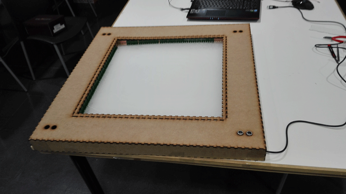
RESULT :
It is an interactive window which has 200 LEDs in the borders (50 each) of an engraved acrylic board. The acrylic is a light transmissive material so the light goes through the lines etched in the acrylic.
ANALISIS
What does it do?
The LED starts to light up when someone is closer than 20 cm. And the light is transmitted through the lines etched in the acrylic.
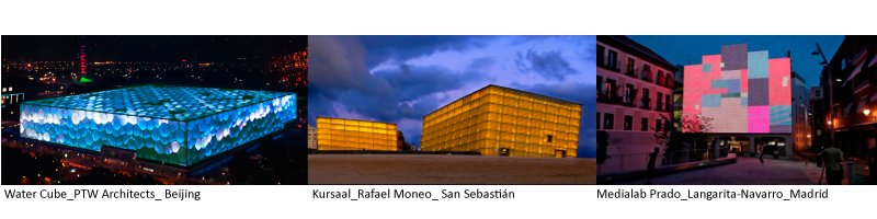
Who's done what beforehand?
Some of my architecture facade reference are:
What did you design?
- The MDF structure
- The holding pieces
- The electronics
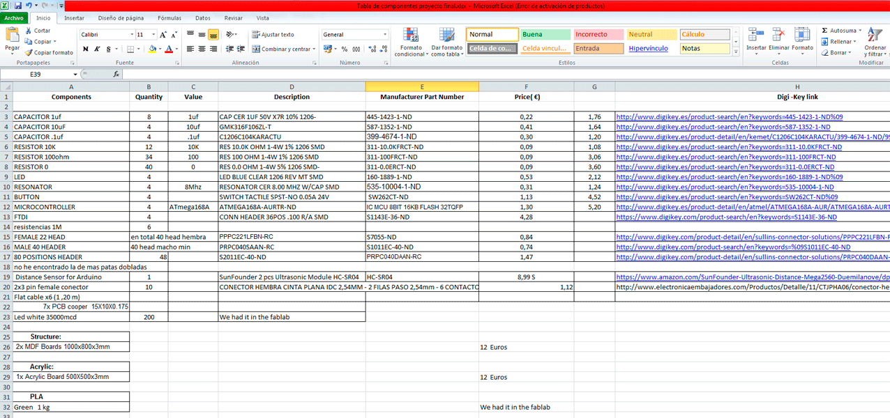
What materials and components were used?
Where did they come from?
How much did they cost?
This is the BOM of my final project: 134,58 €
What parts and systems were made?
What processes were used?
- Structure_Laser cutter: MDF Boards
- Acrylic_Laser cutter
- Electronics _Rolland Mill MDX_20:
__ 4x LED Array Boars
__4x Slaves
__1x Master Distance Sensor Board
- 3d Printing: the holding pieces
What questions were answered?
I got a nice effect with the acrylic but the light doesn’t go too far, as I will continue the researching of the effects of my window, because I want it to be part of my final architecture project which I am working on, I will study other types of light transmissive material.
What is the deadline?
How much time do I have left?
The deadline project was June 22th, and I had the project working as it should do.
What tasks have been completed, and what tasks remain?
Thinking about the future, I think I will continue the researching of the effects of my window, because I want it to be part of my final architecture project which I am working on. But my final Academy Project is ready.
What has worked?
What hasn’t?
What questions still need to be resolved?
In general the project works as it should do, I got a nice effect with the acrylic but the light I doesn’t go too far so in future researching I have to improve it
What have you learned?
I learned a lot in many aspects, especially electronics and light transmitters materials behavior.
For the holding pieces as I was in the process of design I used the 3d printer, but I realized that as I did so many pieces, once I have the final design it could be faster if I would have done them with molding and casting.
This would be the wax mold for the pieces that I designed:
Plan for dissemination
Thinking about the future, I think I will continue the researching of the effects of my window, because I want it to be part of my final architecture project which I am working on.
My final architecture project is a leisure center and for me it is important the interactive architecture elements.
Once I finish my final architecture project I will think about future possibilities to make it real, I am thinking to do crowd funding to get it.
How was it evaluated?
In my final project illuminates the acrylic with the LED array that I put in the borders, and the input is the distance sensor. The LED starts to light up when someone is closer than 20 cm. And the light is transmitted through the lines etched in the acrylic.

Este obra está bajo una licencia de Creative Commons Reconocimiento-NoComercial-CompartirIgual 4.0 Internacional.