Tim Bruening - Fab Academy 2016
Week #2 - Computer Aided Design.
The second week took us in to Computer Aided Design (CAD).
We were shown many versions of 2D, 2.5D and 3D CAD packages.
Some ran in a Windows environment and some ran in Ubuntu.
Some ran in both.
Here is a list of tasks as I see them for the second week.
(Not necessarily in this order)
-
Download some different CAD packages.
-
Try to draw a project in as many CAD packges as possible, given the
time contraints.
-
Create 2D and 3D drawings of the project.
-
Create document showing and describing how drawings were
created using text, screenshots and actul files.
-
Push the files to GIThub. (include all files; text, images,
screenshots and drawings).
Download/Use different CAD packages.
I downloaded/used four different CAD packages. Tinkercad,
Inkscape, AutoCAD and SolidWorks.
Practice drawing in the different graphic packages.
Tinkercad
allows you to drag different 3D shapes from a librry to the workplane.
You have the ability to edit the shapes through clicking and
dragging. The minimum resolution appears to be 1mm.
I was
not able to find anyway to change that. I would like to be
able
to use inch units but could not find a way. The
shapes are
easy to combine into one solid part. Tha only way to save the
part is to use their website or download to Thingiverse. In
general this is a decent CAD program for inexperinced users to create a
quick part. I need to investigate further to find ways to
increase its accuracy.
Tinkercad is pretty intuitive. It assumes you are going to
combine the shapes into one component.
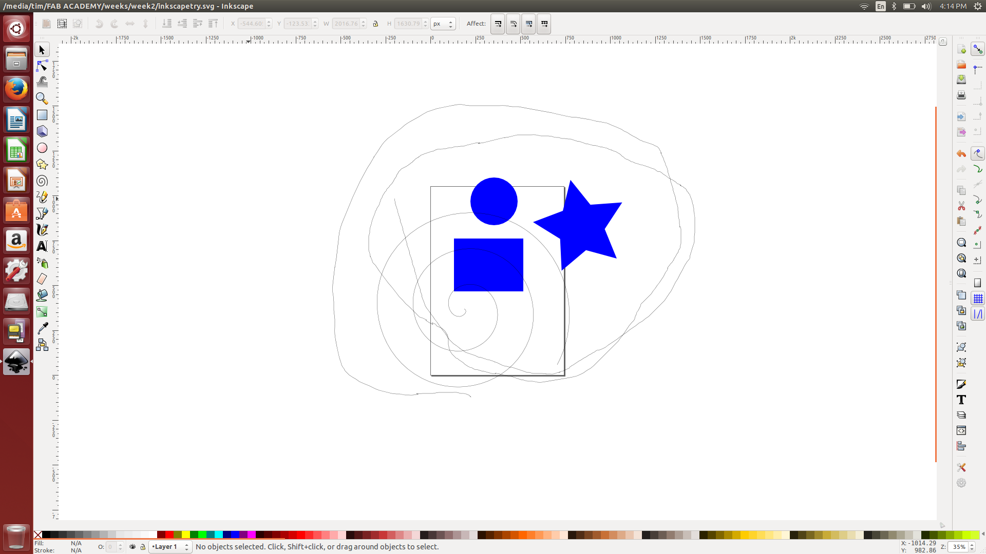
Inkscape looks a lot like TinkerCAD. It has a lot of clicking
and dragging of shapes. I spent a couple of hours
downloading, setting it up and exploring. I was not able to
do much real "drafting" with it. I even had touble defining
specific measurements for the shapes I created. I would need
a lot more time to get familiar with it. One thing that
caught my eye was its ability to trace a bitmap and turn it into a
vector. I plan on coming back to explore that feature.
AutoCAD
is much more powerful than TinkerCAD. I must confess I have
some
experience with AutoCAD. I was able to draw the parts in 2D
without much trouble. The resolution in AutoCAD is much
greater
than TinkerCAD. I have my system set for inches and four
decimal
places. So far there are 2 components in the drawing with
front,
top and right side views. I will include other components as
my
design is finalized.
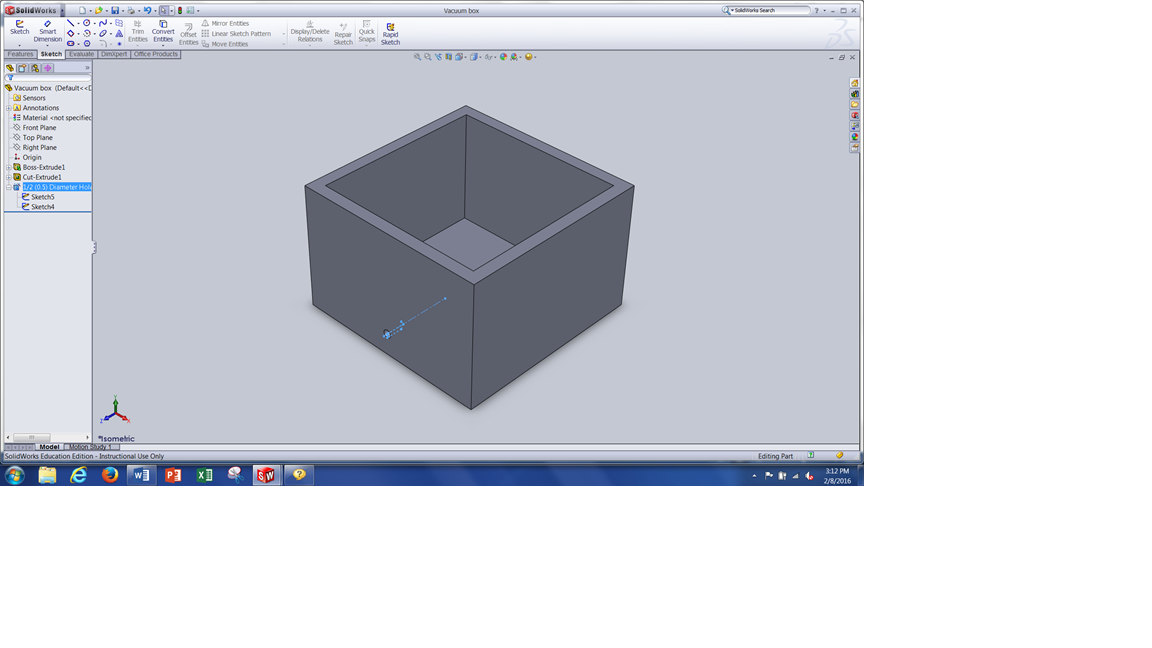
Solidworks is used to create a 3D solid.
I drew the two main parts of the vacuum as one component
each.
In reality there are several parts in each component.
As I
get better with Solidworks I will try to update my drawings into
assemblies.
Create 2D and 3D drawings of my project.
I started with 2D drawings in AutoCAD. One
part is the vacuum box the molds will go into. There will be
an insert with holes to allow the vacuum to work. I plan on
adjusting the depth of the box by using different height wood blocks.
Initial size of the blocks will be 1.5" x 3" x 4".
I will make at least 4 of them to support the insert tray.
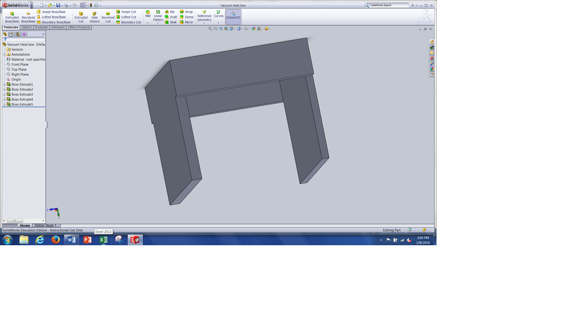
The second part is the vacuum heat box. It has to be
able to move over the vacuum box so the width and height will be 1"
larger then the vacuum box.
Next I used SolidWorks
to creat 3D models of both the vacuum bao and the vacuum heat box.
Eventually I will include the heating element and the rollers
needed.
Graphic documentation
The following is a TinkerCAD image I created during
experimentation.

The following is an Inkscape image I created during
experimentation.
Here is an AutoCAD screenshot of my drawing

And last are screenshot of SolidWorks showing the vacuum
box and the vacuum heat box.
Tim's Week #2 files:
CAD files for 2nd week.
SoliWorks drawing
file.
AutoCAD drawing
file.
Week #2 html file
Back to index