

ex - clear (PWM_port, PWM_pin); clears PORTA & PA6
ex - output (PWM_direction, PWM_pin); sets as outputts
------------------------------------------------------------------
The next parts of the program are the main loop.
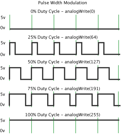
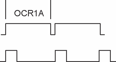
OCR1A = 1250 This means that the Output Compare Register will reset when 1250 is achieved.
position_delay(); This rests the delay. This function was located in one of the libraries defined earlier.
Here is a visual to understand what OCR1A is controlling. It would be shorter is the PWM is lower.
-----------------------------------------------------------------
The file "hello.servo.44.2.c" will control two servos. The program sets up a routine where the servos go back and forth with movement.
The files to compile the codes and run the servos are found on the FAB Academy website.
- hello.servo.44.c (controls one servo)
- hello.servo.44.2.c (controls two servos)
- hello.servo.44.make (programs the board and sets fuses to control one servo)
- hello.servo.44.2..make (programs the board and sets the fuses to control two servos)
To compile the code to control one servo - make -f hello.servo.44.make
To complie the code to control two servos - make -f hello.servo 44.2.make
To flash the code to the atttiny44 - make -f hello.servo.44.c
One servo will be cycling.
To flash the code to the attiny44 - make -f hello.servo.44.2.make
Two servos will be cycling.
Test the PCB.
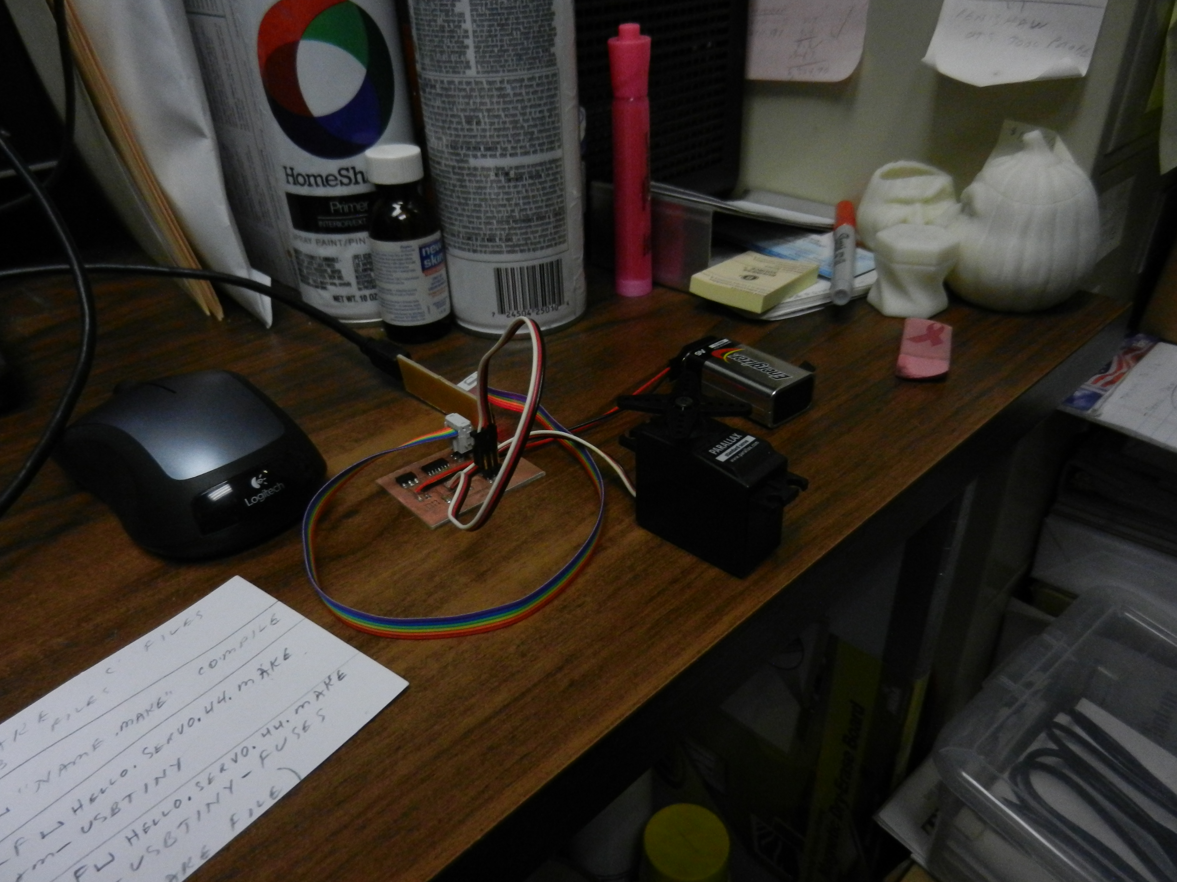
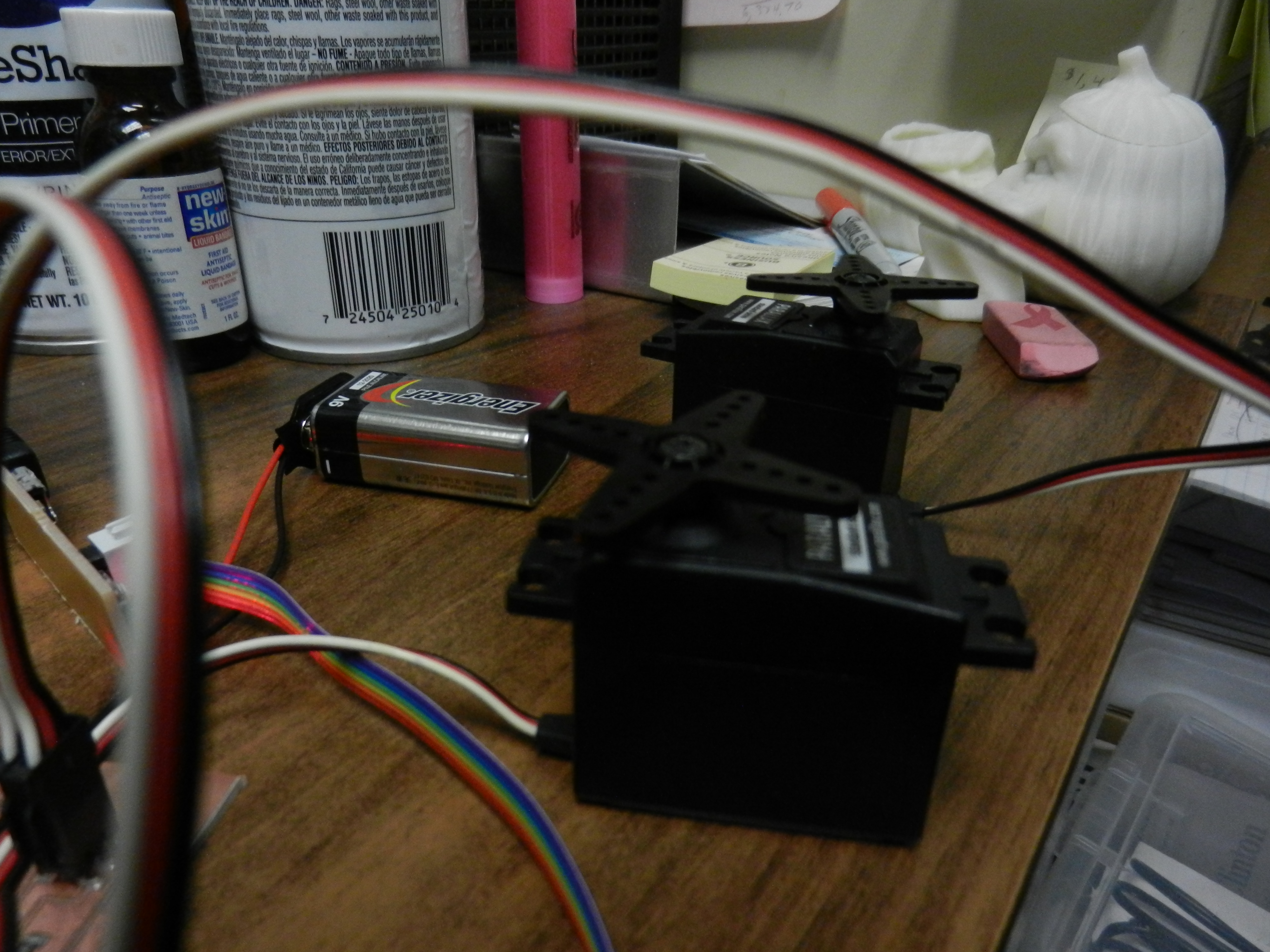
I alternated between the two programs. hello.servo.44.c hello.servo.44.2.c The first one only controls one servo and the second one has a routine to control both. The image on the right shows one servo working. The image on the left shows both servos working.
Document the process and list any problems encountered.
I must be getting a litle better with my electric circuits. I took some time to create the schematic, board image, populate the board and program the PCB.
Other than my on going deficiencies in programming I am really starting to understand what is going on with circuit boards.
Create the Output Circuit for the Final Project
Build PCB Boards
I needed to build two boards for this project. After discussions with my mentor and other electronics people I decided to make a smaller, separate board for the hall effect sensor.
It will be easier to place and keep the main board away from the heat.
The main board will house the ATTiny44 micro controller and all the 2 x 2 connectors needed to integrate all components.
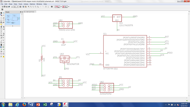
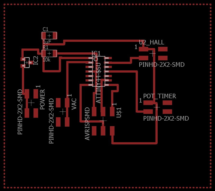
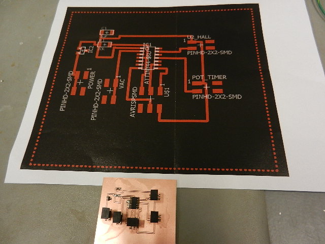
Here is a screenshot of the schematic for the ATTiny44 board.

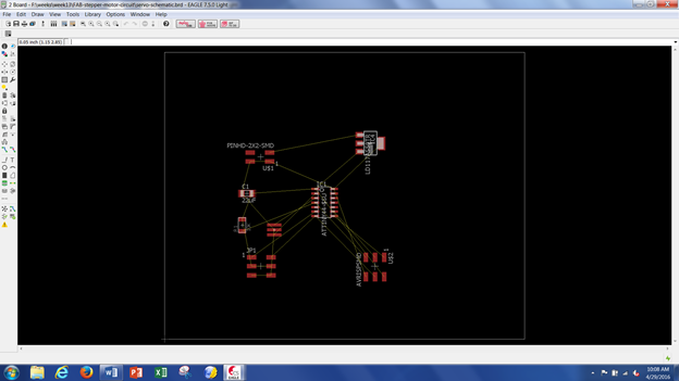
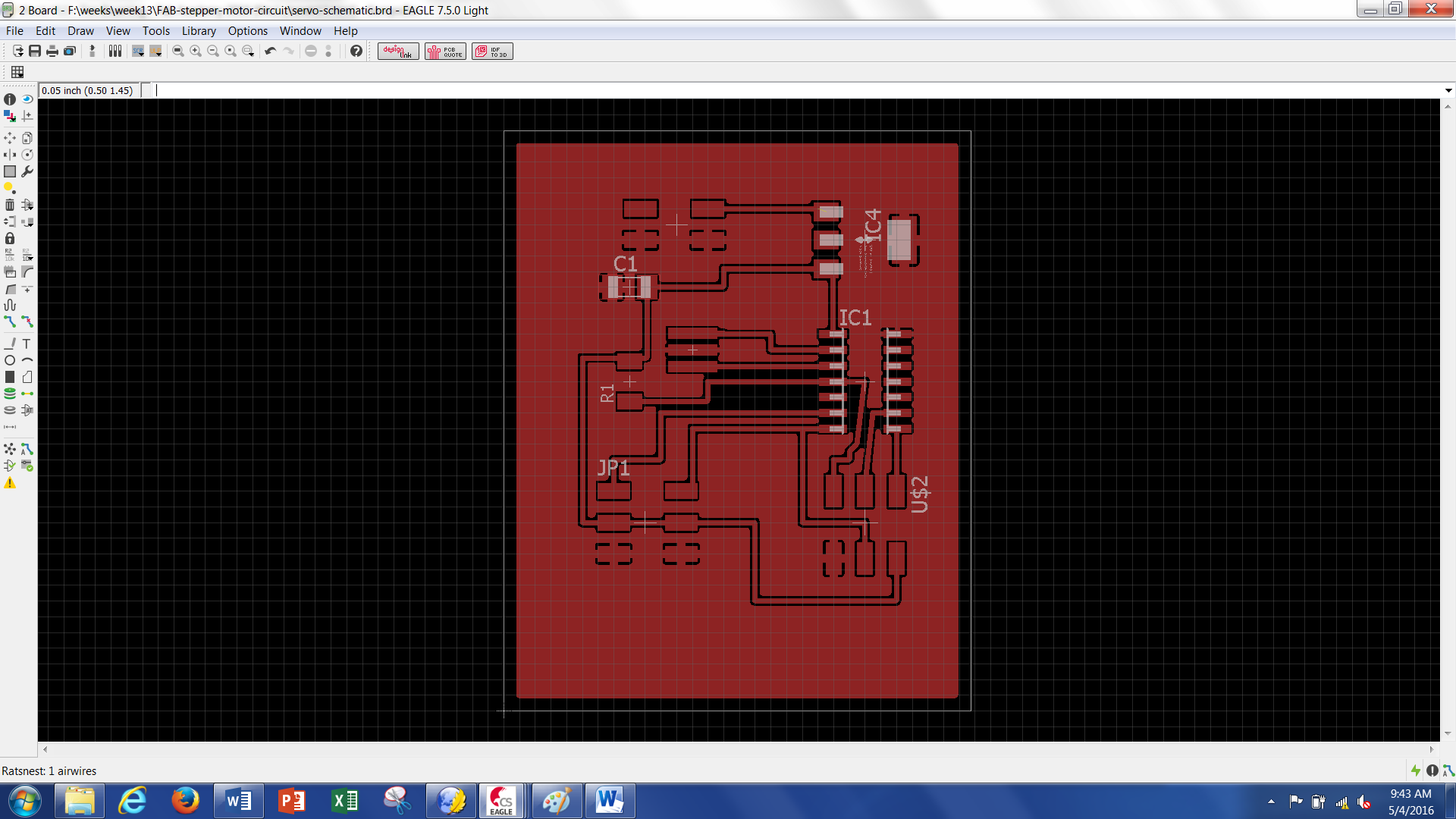
Here is a screenshot of the traces for the final ATTiny44 board.
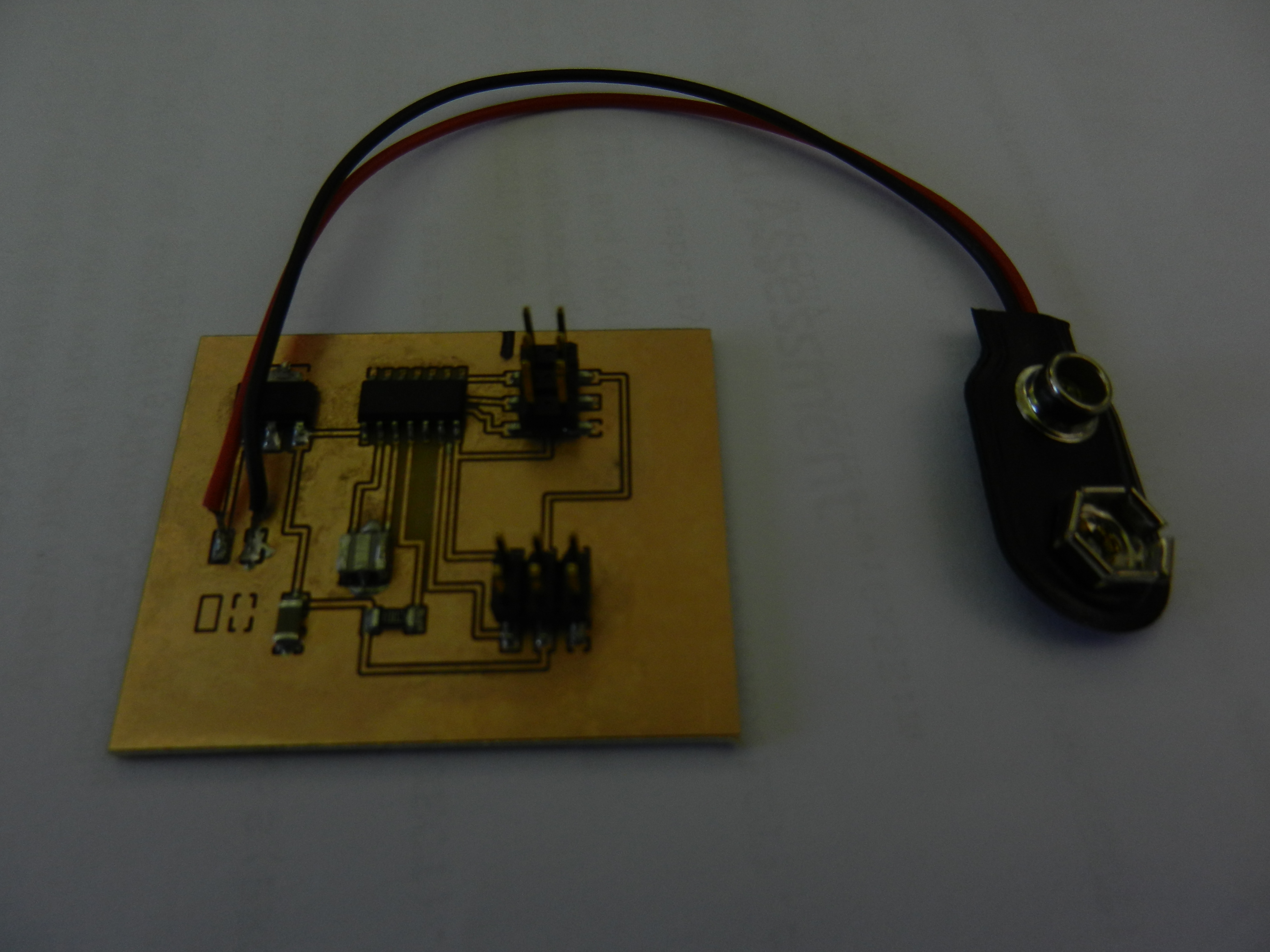
This is a picture of the completed ATTiny44 board and the traces used to make it.
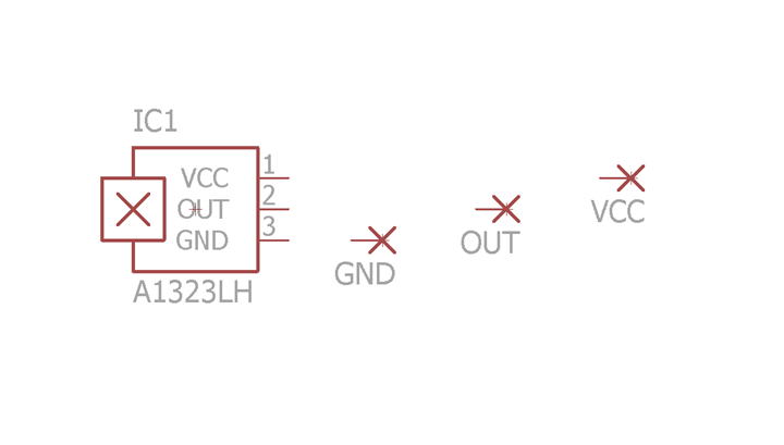
Here is the schematic for the hall effect sensor.
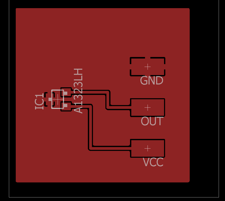
Here are the board traces for the hall effect sensor.
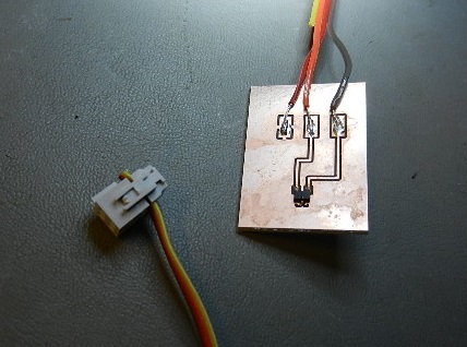
Here is the hall effect sensor before populating.

Here is the finished hall effect sensor board.
Program the Boards
For my final project I decided to use Arduino programming. To me it seems simpler than the "C" programming we used in earlier programs.
The Arduino code is easier for me to understand. I am able to walk through each line of code and explain what is happening.
Here is my final project program. The explanations in RED are not part of the program They are added for explanation only.
void
setup()
{
setup only runs
once on startup
// put your setup code
here, to run once:
pinMode(10,OUTPUT);
define pin #10 as
an output
}
int
sensorValue =0; // variable for hall read on A0
set hall effect input to zero
int
TimeValue=0; //
potentiometer input
set pot.
input to zero
int
timescale=0; // pot variable
set pot. variable to zero
void
loop()
{
loop forever
constantly scan code
// put main code here, to
run repeatedly:
sensorValue
= analogRead(0); //
read voltage on A0
hall
effect
input from A0
TimeValue
=
analogRead(2); //
read voltage on A2
pot.
input
from A2
timescale = TimeValue * 10;
controls variable
delay from pot.
if(
sensorValue < 200)
true if correct
magnetic pole is present
{
delay(10000);
wait 10,000
milliseconds (10 seconds)
delay(10000);
“
delay(10000);
“
delay(10000);
“
delay(10000);
“
delay(10000);
“
delay(10000);
“
delay(4000);
wait 4,000
milliseconds (4 seconds)
delay (timescale);
wait value from pot.
digitalWrite(10,HIGH);
set pin #10 to high
(turn on vacuum pump)
}
while(sensorValue
< 200)
keep pin #10 value
high as long as sensorValue < 200
{
(as long as sensor
detects magnetic field)
sensorValue
= analogRead(0);
sets sensorValue to
500 when burner is moved
away from hall
effect sensor
}
digitalWrite(10,LOW);
set pin #10 to low
(turns off vacuum pump)
}
Test Boards
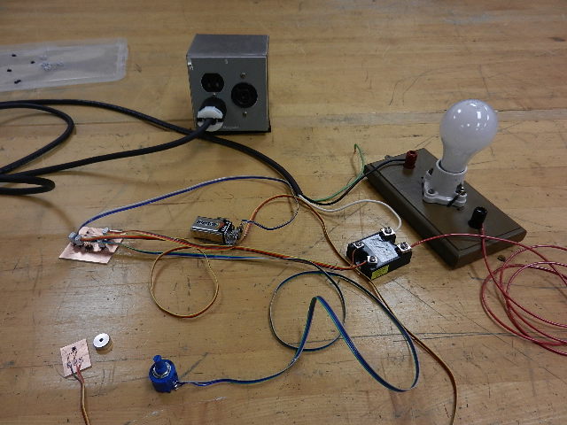
Now that the boards are programmed they have to be tested. I wired them up using a 9 volt battery and 110 volt jumper wires.
The light bulb is filling in for the vacuum pump.
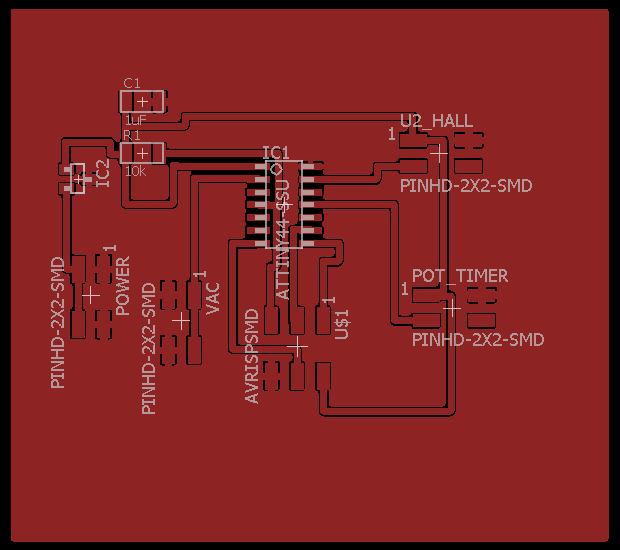
Looking at the ATTiny44 board schematic and board images you will see four 2x2 connectors. These are used to connect all the components together.
Power 2 x 2 --- This connector has a 9 volt battery connected to it. 2 pins connect to ground (GND) and 2 pins are connected in series to the voltage regulator.
The voltage regulator (on the ATTiny44 board) feeds 5 volts
(VCC) to
the 1uF capacitor, 10k ohm resistor, pin 1 on the Hall 2 x 2, pin 1 on
the Pot 2 x 2 and the AVRISPSMD.
Hall 2 x 2 ---- This connector has 1 pin to VCC, 1 pin to GND, 1 pin to
Pin 13 on the ATTiny44 and one pin unused.
Pot Timer 2 x 2 ---- 1 pin to VCC, 1 pin to GND, 1 pin to Pin 11 on the ATTiny44 and 1 pin unused.
VAC 2 x 2 ---- 2 pins connected to Pin 2 on the ATTiny44 (PB0 output to terminal on DC side of relay) and 2 pins (GND) to other terminal on DC side of relay.
---- 2 wires to GND and 2 wires to Pin 2 are twisted together.
The AC side of the relay has one wire coming from the hot 110 volt wire and one wire going to one side of the outlet in the blue box.
The other wire (neutral) from AC 110 goes directly to the remaining terminal of the outlet.
The vacuum pump is plugged into the outlet. It will only come after the programmed delays.
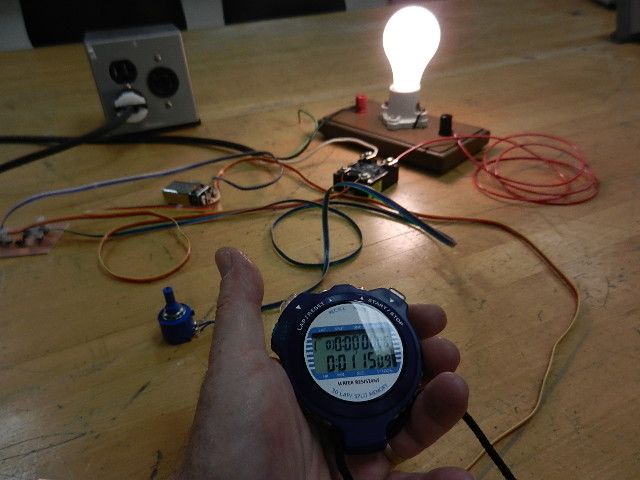
The ATTiny44 board is programmed with a 75 second delay (determined through testing).
Here you can see the test setup.
Here you can see the test setup after the hall effect sensor has been manually triggered.
You can see the stopwatch recorded 1 minute and 15 seconds. 75 seconds total.
Tim's Week #13 files:
*.c and *.make files
Back to index