In the last week we are tasked to complete our final projects. I decided to build Grandpa's Vacuum Former. I am building Grandpa's FABlab in my basement for the grandkids. So far I have an XYZ DaVinci Jr 3D printer, a Silhouette Cameo vinyl cutter and a Full Spectrum 45 watt 12" x 20" laser. I am trying to use the FAB Academy to increase either my knowledge of FABlabs, to build accessories for my existing equipment or to build new machines for the lab. In week 7 I built a cart for my laser.
I decided to build a
vacuum former so anyone in Grandpa's lab can make vacuum formed parts
such as
candy molds or halloween masks.
Here is a list of the steps and tasks I used to make Grandpa's Vacuum Former.
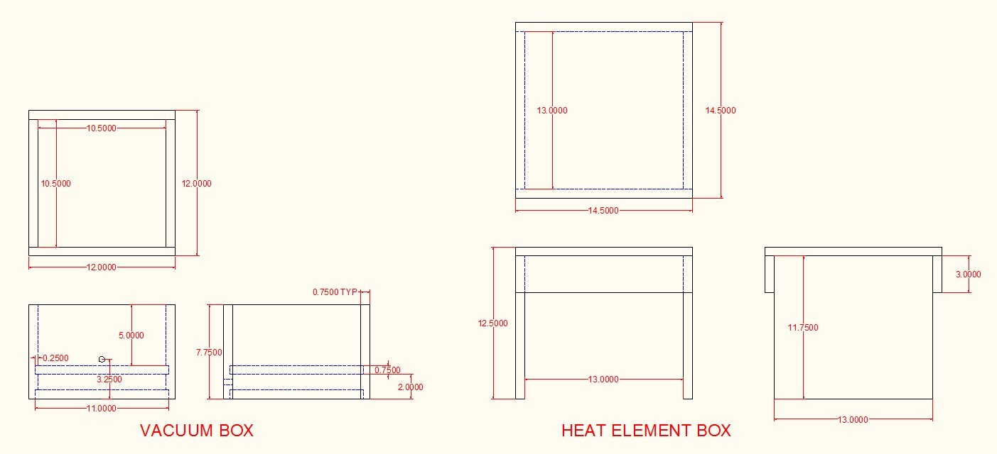
The first thing I needed to do was to design the vacuum former. I decided to make the boxes out of 3/4" plywood and add foil tape to help with insulation.
I drew up a simple machine using AutoCad that had two boxes. One for the vacuum chamber and one for the heat chamber. I have an old vacuum pump that I use in my fluid Power class that will work for the power supply.
Here is a a screen shot of the design.
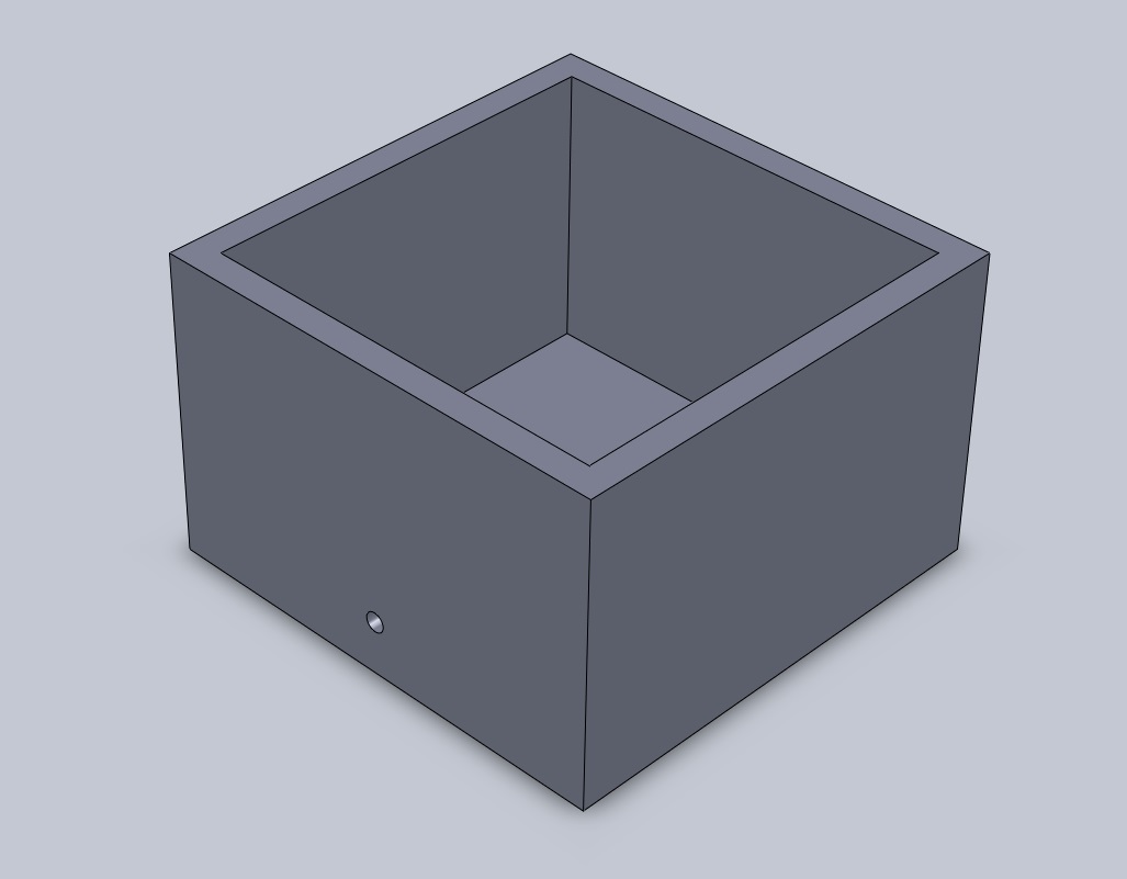
I then created 3D drawings using Solidworks. Here are two screenshots showing the heat box and the vacuum box.

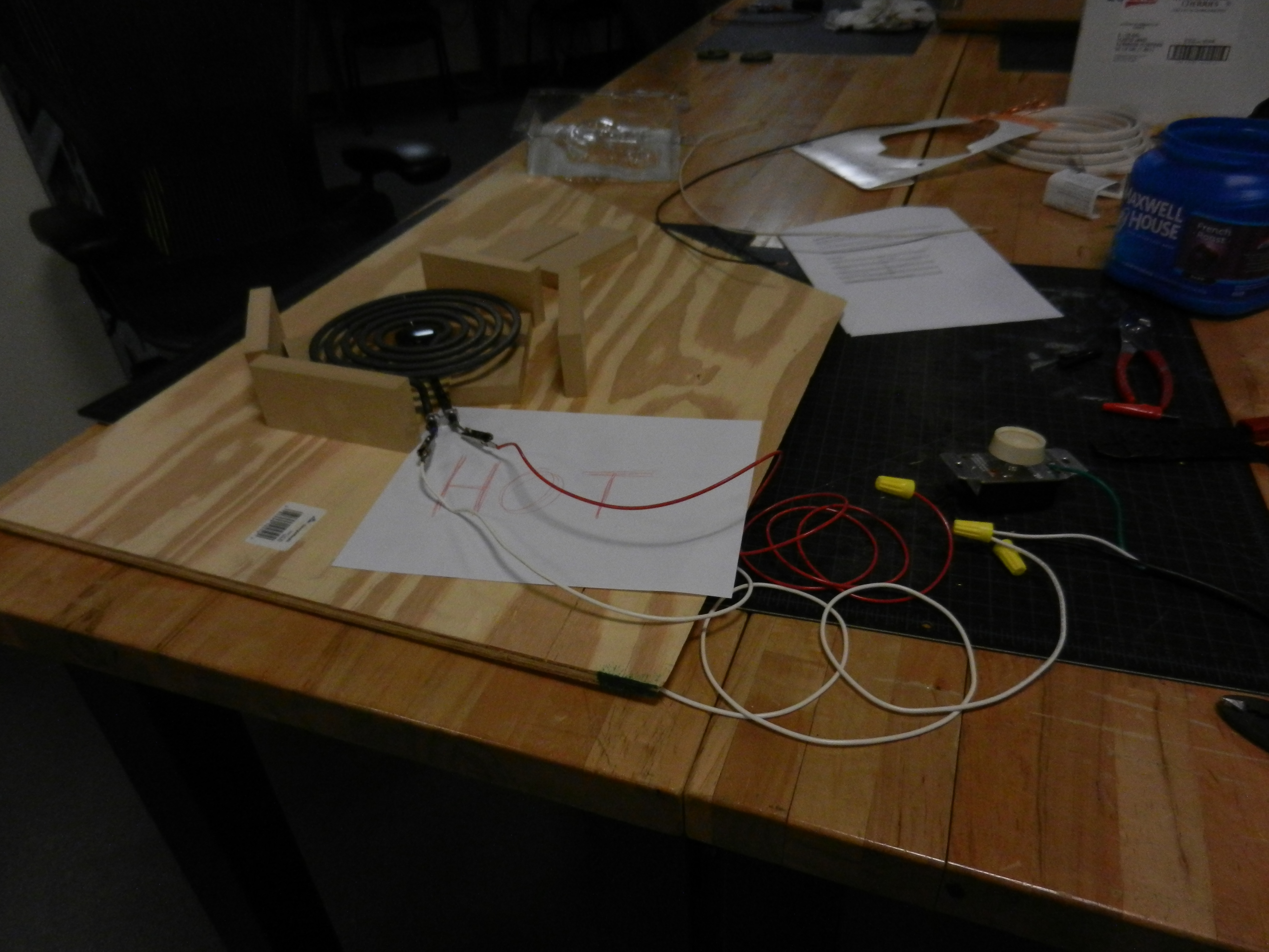
I bought an 8" replacement electric stove burner from Home Depot (see BOM). In order to verify my idea of using a replacement stove burner as my heat source I had to verify that it would work.
The burner was designed for 220 volts and I wanted to run it on 110 volts. I rigged up a circuit to test the burner using a two way dimmer switch, some 14 gage jumpers wires and a repair electrical cord.
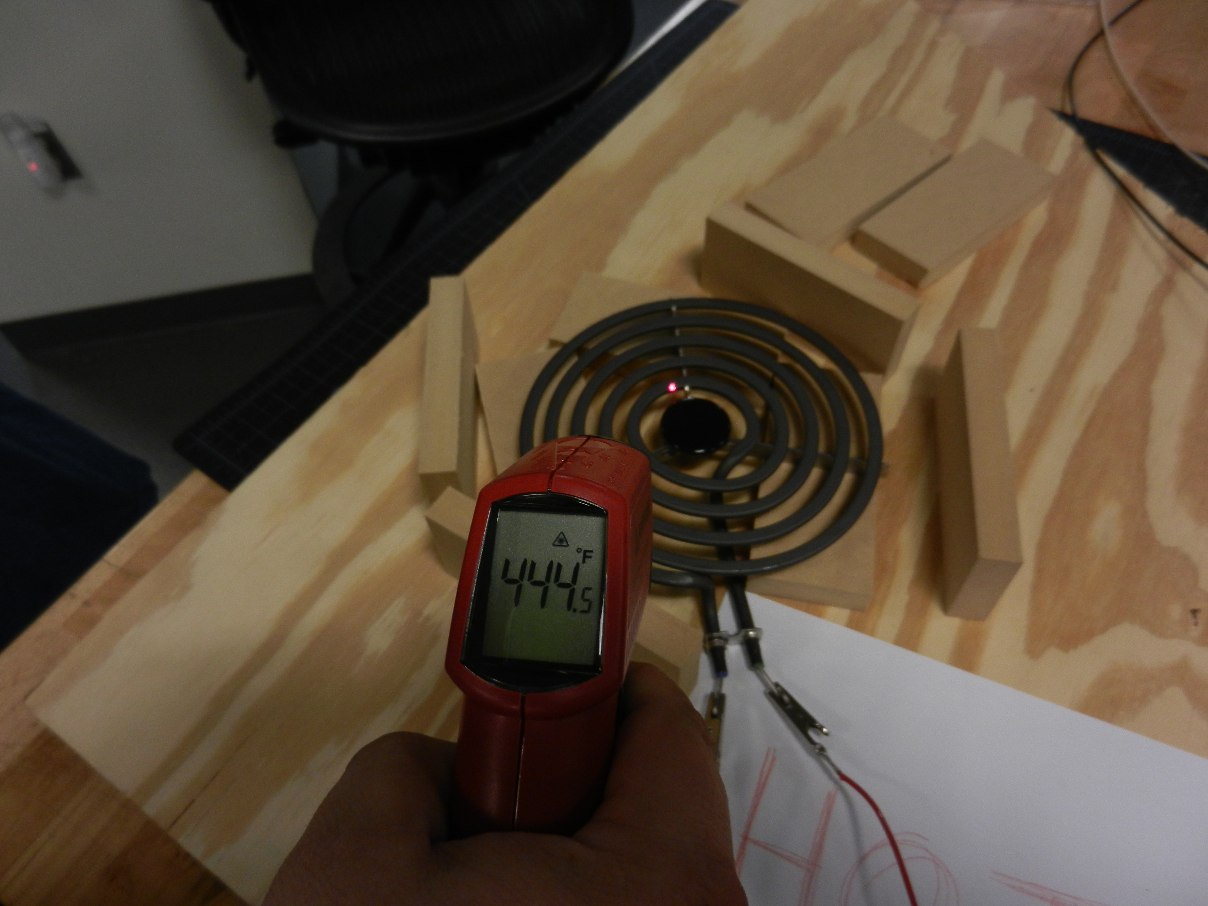
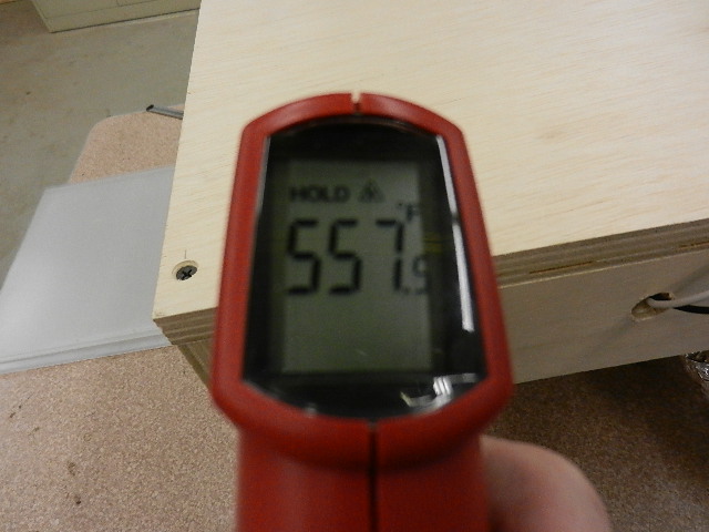
The power source I used had circuit breaker protection. It took quite a while to heat up but the temperature eventually reached 44 degrees Fahrenheit. The dimmer switch did function to control the temperature.
The final version of my project did not include the dimmer. I was able to get a higher temperature without it.
Here is a picture of the testing setup.
Here is a picture of the infrared thermometer I used to gage the test.
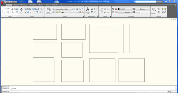
Next I created the wood boxes I needed. Some of the cuts were made using a Shopbot and some were made using a table saw.
I could have cut the dadoes on the shopbot but I was in a bit of a time crunch. A table saw is a much better tool to make the dadoes (grooves) I needed to assemble the boxes.
Here is an AutoCAD picture of the parts to be cut on the shopbot.
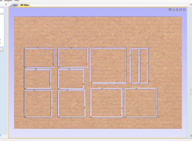
Here is screen shot of Aspire showing the cutouts of the parts.
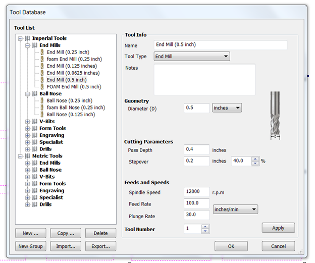
Here is a sreenshot of the speeds and feeds used on the Shopbot to cutout the parts
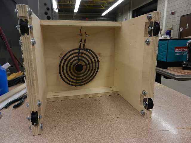
Here are two pictures of the heating box. It has the burner suspended from the top. It cannot come in contact with the wood.

The vacuum box had to be built with a compartment that could minimize leakage. The more leakage incurred the less vacuum is available and the process would take longer.
If you look at the Acad drawing you will see that I had dadoes (grooves) around the perimeter of the vacuum box where the bottom of the chamber would be attached.
During assembly all joints were both glued and screwed to make a tight fit. I also lined the vacuum chamber with foil tape to help with insulation.
Here is a picture of the vacuum assembled with the foil tape applied.
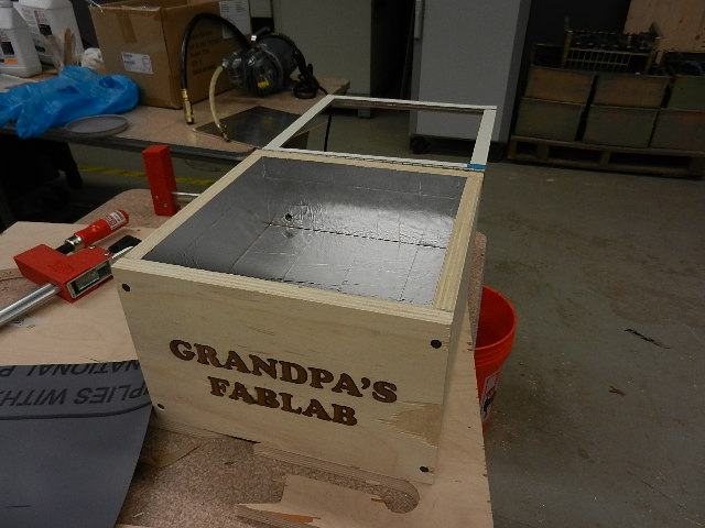
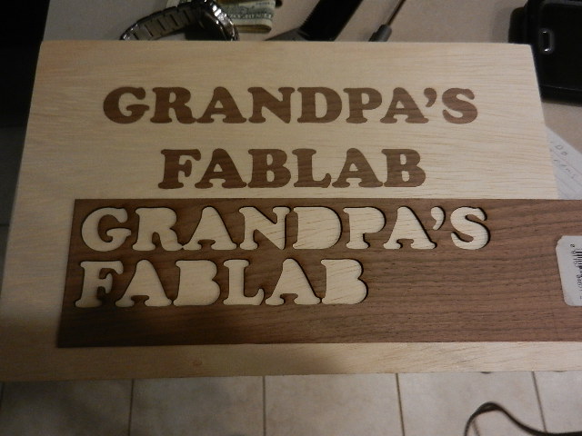
I also decided to personalize the box and inlaid "GRANDPA'S FABLAB" into the front of the box. The inlaying process took place before the assembly of the box.
You can see the finished inlay is the picture above. To create the inlay I raster lasered the letters into the plywood. I repeated the process six times until the cavities were deep enough.
I then turned the letters into hairline outlines and cut the letters out of 1/8" thick walnut.
Here is a picture of the board and the walnut piece that is leftover.
The letters were glued into the cavities and allowed to dry overnight. The next day I used a drum sander to smooth out the inlay.
Here is a picture of the sanding process.

The next step is to assemble the vacuum box. All parts were glued and screwed together. After drying time I attached the rubber gasket to the top of the box to help seal the box during use.
I attached a 13.5" x 13.5" piece of rubber to the top using contact cement.

I then trimmed the rubber gasket to fit the inside of the box.
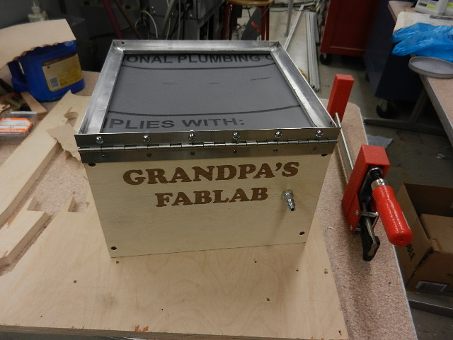
I also attached a 1/2" adhesive foam strip to the clamp bracket. Next I attached the clamp bracket using a piano hinge in the rear of the box.
I had to push down slightly on the bracket to allow for the force needed later to hold the plastic sheet.
The last thing needed for the vacuum box was to attach the latches.

I also epoxied a quick disconnect pneumatic into the back of the box to attach the vacuum hose. I had to wrap the hose with foam tape and foil tape to keep it from over heating.
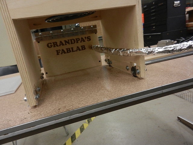
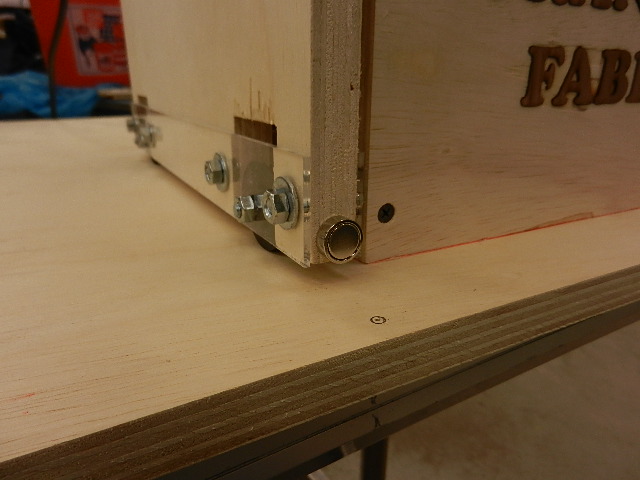
The last thing I had to do was attach the rollers to the heat box.
I decided to make the rollers on the 3D printer. They would be inexpensive and exactly what I wanted.
Here is a picture of the test roller after 3D printing?

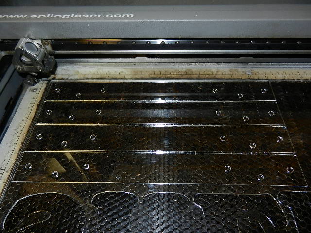
I then made roller frames to attach them to the sides of the heat box. They are made of 1/8" thick clear acrylic and cut out on the laser.
Here is a closeup of one roller installed.

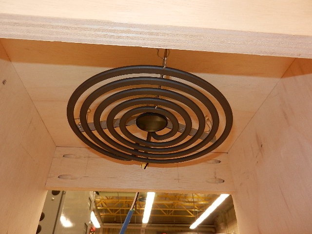
Here is a view from the bottom of the heat box showing the rollers attached and the suspended heat element.
Before I went through all the effort to make and program the PCBs I decided to do a manual test of the vacuum former.
I hooked up the heating element. This time without the dimmer switch. I also attached the vacuum pump using quick disconnects.

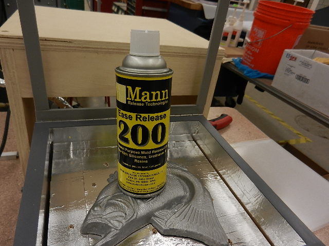
I inserted a model into the vacuum box and treated it with release a agent.
Next I placed a piece of .020" thick PETG on top of the rubber and clamped it into position.

It took about 10 minutes for the burner to get up to temperature.
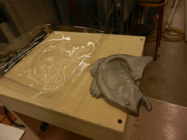
I ran multiple tests on a fish model trying to determine the best timing sequence for the .020" PETG material.
The part did not have very good definition. The surface area of the fish was too great.
I used a 3D printed model of a head for the final tests and my video presentation.. It was thinner and had a smaller square inch area.
I also tried a car model to see if the thickness of the model had any effect. I discovered that my small 8" diameter burner did not give out enough heat for a larger model.
The larger the surface area the more heat I can apply to the sheet. I may buy a 10" burner or talk to Neil in China.
During my presentation he mentioned a method to make your own electric elements. I may even be able to make a square element to match the box.

After all the testing I determined that if the burner is preheated if will take about 75 seconds to soften the sheet for vacuum forming.
Now that I new the vacuum former would heat up enough and form the plastic sheet I needed to work on the electronic components.
I decided to test all the components before building the PCBs. Once the PCBs are integrated into the circuits I wanted to eliminate other components during troubleshooting.
As Neil stated, take little steps. The first thing to check is the solid state relay. I had to make sure that a signal of 5 volts would cause the relay to output 110 volts.

Here is the test setup using small power supply. 110 volt jumper wires will be connected to the AC terminals.
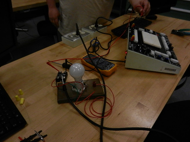
Here is the proof that the relay works. The 110 volt lights when 5 volts is applied to the relay.

I needed to build two boards for this project. After discussions with my mentor and other electronics people I decided to make a smaller, separate board for the hall effect sensor.
It will be easier to place and keep the main board away from the heat.
The main board will house the ATTiny44 micro controller and all the 2 x 2 connectors needed to integrate all components.
Here is a screenshot of the schematic for the ATTiny44 board.

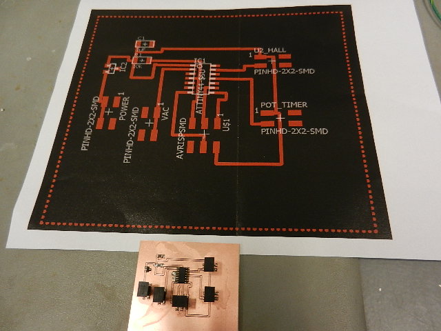
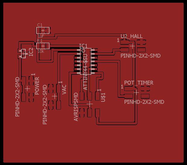
Here is a screenshot of the traces for the final ATTiny44 board.
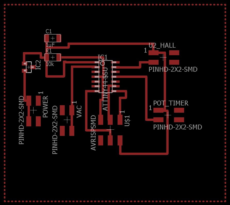
This is a picture of the completed ATTiny44 board and the traces used to make it.
Here is the schematic for the hall effect sensor.
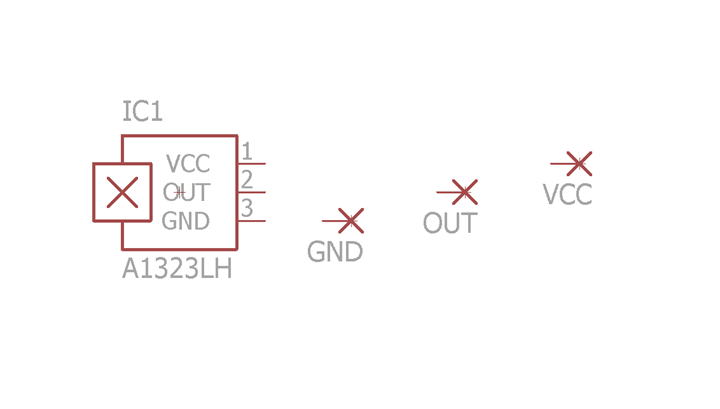
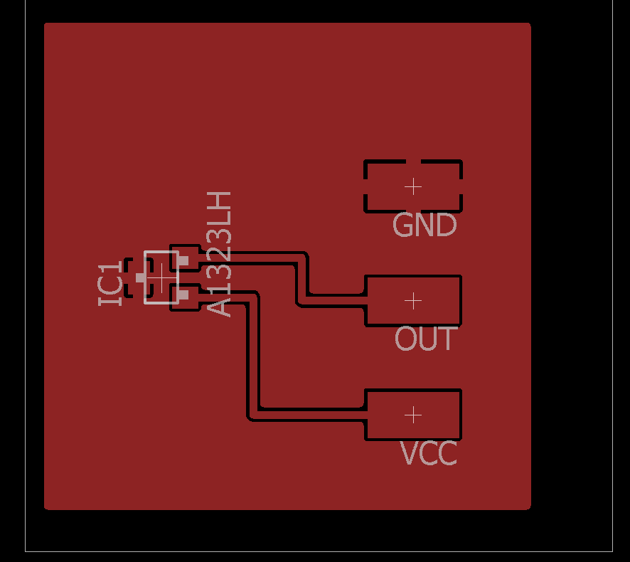
Here are the board traces for the hall effect sensor.
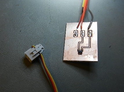
Here is the hall effect sensor before populating.

Here is the finished hall effect sensor board.
For my final project I decided to use Arduino programming. To me it seems simpler than the "C" programming we used in earlier programs.
The Arduino code is easier for me to understand. I am able to walk through each line of code and explain what is happening.
Here is my final project program. The explanations in RED are not part of the program They are added for explanation only.
void
setup()
{
setup only runs
once on startup
// put your setup code
here, to run once:
pinMode(10,OUTPUT);
define pin #10 as
an output
}
int
sensorValue =0; // variable for hall read on A0
set hall effect input to zero
int
TimeValue=0; //
potentiometer input
set pot.
input to zero
int
timescale=0; // pot variable
set pot. variable to zero
void
loop()
{
loop forever
constantly scan code
// put main code here, to
run repeatedly:
sensorValue
= analogRead(0); //
read voltage on A0
hall
effect
input from A0
TimeValue
=
analogRead(2); //
read voltage on A2
pot.
input
from A2
timescale = TimeValue * 10;
controls variable
delay from pot.
if(
sensorValue < 200)
true if correct
magnetic pole is present
{
delay(10000);
wait 10,000
milliseconds (10 seconds)
delay(10000);
“
delay(10000);
“
delay(10000);
“
delay(10000);
“
delay(10000);
“
delay(10000);
“
delay(4000);
wait 4,000
milliseconds (4 seconds)
delay (timescale);
wait value from pot.
digitalWrite(10,HIGH);
set pin #10 to high
(turn on vacuum pump)
}
while(sensorValue
< 200)
keep pin #10 value
high as long as sensorValue < 200
{
(as long as sensor
detects magnetic field)
sensorValue
= analogRead(0);
sets sensorValue to
500 when burner is moved
away from hall
effect sensor
}
digitalWrite(10,LOW);
set pin #10 to low
(turns off vacuum pump)
}
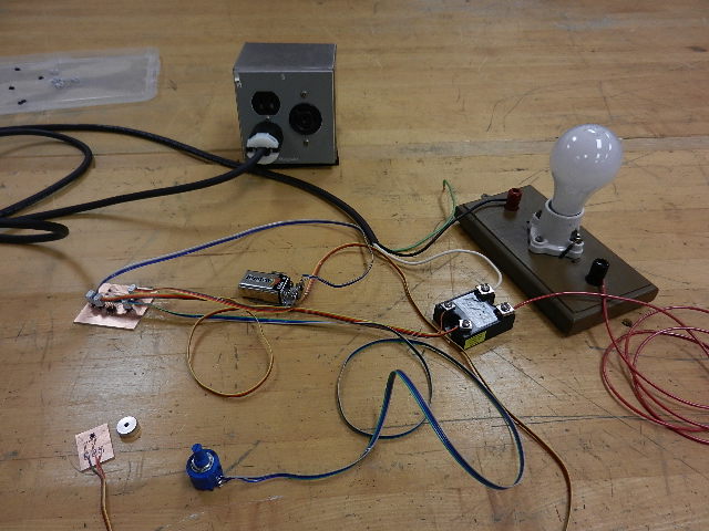
Now that the boards are programmed they have to be tested. I wired them up using a 9 volt battery and 110 volt jumper wires.
The light bulb is filling in for the vacuum pump.
Looking at the ATTiny44 board schematic and board images you will see four 2x2 connectors. These are used to connect all the components together.
Power 2 x 2 --- This connector has a 9 volt battery connected to it. 2 pins connect to ground (GND) and 2 pins are connected in series to the voltage regulator.
The voltage regulator (on the ATTiny44 board) feeds 5 volts
(VCC) to
the 1uF capacitor, 10k ohm resistor, pin 1 on the Hall 2 x 2, pin 1 on
the Pot 2 x 2 and the AVRISPSMD.
Hall 2 x 2 ---- This connector has 1 pin to VCC, 1 pin to GND, 1 pin to
Pin 13 on the ATTiny44 and one pin unused.
Pot Timer 2 x 2 ---- 1 pin to VCC, 1 pin to GND, 1 pin to Pin 11 on the ATTiny44 and 1 pin unused.
VAC 2 x 2 ---- 2 pins connected to Pin 2 on the ATTiny44 (PB0 output to terminal on DC side of relay) and 2 pins (GND) to other terminal on DC side of relay.
---- 2 wires to GND and 2 wires to Pin 2 are twisted together.
The AC side of the relay has one wire coming from the hot 110 volt wire and one wire going to one side of the outlet in the blue box.
The other wire (neutral) from AC 110 goes directly to the remaining terminal of the outlet.
The vacuum pump is plugged into the outlet. It will only come after the programmed delays.
The ATTiny44 board is programmed with a 75 second delay (determined through testing).
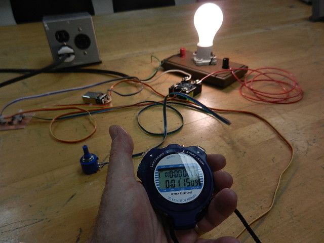
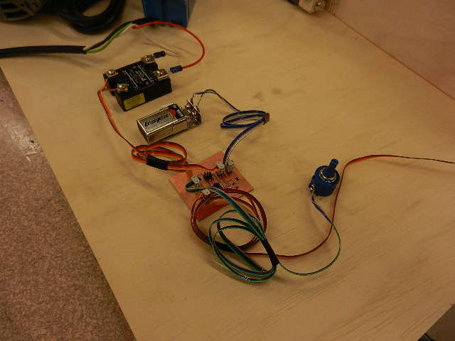
Here you can see the test setup.
Here you can see the test setup after the hall effect sensor has been manually triggered.
You can see the stopwatch recorded 1 minute and 15 seconds. 75 seconds total.
Now is the time to assemble all components on a base board and position the hall effect sensor and the magnet. (See wiring explanation above)
The ATTiny44 is powered by a 9 volt battery. It is connected by a battery wire to the 2 x 2 connector on the board.
There are four 2 x 2 connectors on the PCB. One for the battery. One for the potentiometer input which gives an extra 1 to 10 seconds delay.
Another one for the input from the hall effect sensor showing the heat box in position.. Finally, there is one for the 5 volt DC output to the relay.
The AC portion of the relay is in series with the hot or live wire going to the vacuum pump. The manual switch on the pump is kept in an "on" position.
The relay will send power when the ATTiny44 ends the 75 second delay.
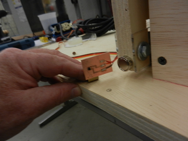
I attached the magnet on the front of the movable heat box and attached the hall effect sensor to allow the heat box to be positioned over the vacuum box.
Here you can see the positioning of the magnet on the front of the heat box.
Here I am calculating where to attach the hall effect sensor.
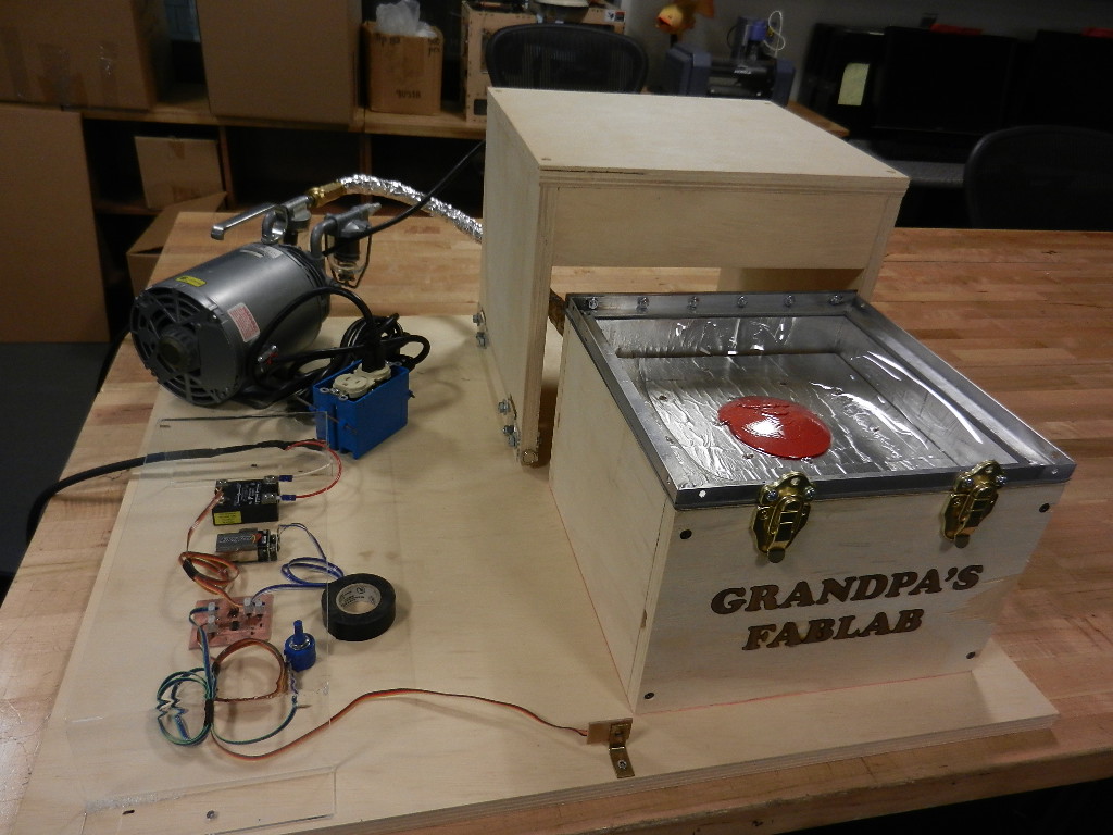
Here is a view of the final electronics and wire positions. I will attach an acrylic cover when all setup is completed.
Last, here is a picture of the final assembly of Grandpa's Vacuum Former.
The easiest way to test the vacuum former is to make a part. I used a 3D model head. It was smaller than some of my earlier models.
I had trouble getting enough heat to form a larger part. I will have to increase the size of the heating element for larger parts.
The part came out just fine and showed all of the details of the original. I consider the test to be successful.
All components worked as planned. Heater, vacuum, PCB board, hall effect sensor and DC/AC relay.
To see the machine video click on the link.
Tim's Presentation video.To see a picture of Grandpa's Vacuum former click on this link.
Here is a link to Week #17 if you want more detail on the Bill of Materials.
I have two plans for the future. First, I want to attach rails and rollers for the heat box to travel on. They were part of my original design but I ran out of time to install them.
Second, I want to install a larger electric burner. The 8 inch burner I used does not heat the entire area of the vacuum box.
The MIT License (MIT)
Copyright (c) <2016> <Timothy A Bruening>
The protected software and hardware is to operate Grandpa's Vacuum Former.
Permission is hereby granted, free of charge, to any person obtaining a copy of this software and associated documentation files (the "Software"), to deal in the Software without restriction, including without limitation the rights to use, copy, modify, merge, publish, distribute, sublicense, and/or sell copies of the Software, and to permit persons to whom the Software is furnished to do so, subject to the following conditions:
The above copyright notice and this permission notice shall be included in all copies or substantial portions of the Software.
THE SOFTWARE ANDM HARDWARE DESCRIPTIONS ARE PROVIDED "AS IS", WITHOUT WARRANTY OF ANY KIND, EXPRESS OR IMPLIED, INCLUDING BUT NOT LIMITED TO THE WARRANTIES OF MERCHANTABILITY, FITNESS FOR A PARTICULAR PURPOSE AND NONINFRINGEMENT. IN NO EVENT SHALL THE AUTHORS OR COPYRIGHT HOLDERS BE LIABLE FOR ANY CLAIM, DAMAGES OR OTHER LIABILITY, WHETHER IN AN ACTION OF CONTRACT, TORT OR OTHERWISE, ARISING FROM, OUT OF OR IN CONNECTION WITH THE SOFTWARE AND HARDWARE OR THE USE OR OTHER DEALINGS IN THE SOFTWARE AND SOFTWARE.