
The Project
Mechanical design was covered as part of a group project to build a functional computer controlled machine.
Brainstorming
The first step of the project was to decide what kind of machine to make. Tim, Matt, Karen and I all came up with a number of good ideas. We considered each of the possibilities and decided to make a fab wind chimes machine. We then got together and determined what needed to be done to complete the project and delegated the different task among the members of the team. I volunteered to build the FabNet board and program the machine.
Building the machine
Building the machine was definitely a team effort. Everyone on the team was responsible for some part of the project but we also helped each other. For example, after Matt laser cut the parts, I helped assemble the linear axis and test them manually to make sure that there was no binding. Tim and I then worked together to assemble the main frame structure. I also helped with the documentation. One of my contributions towards the team documentation was to take the stl file that Karen made for cutting of the parts and uploaded it to my SketchFab account so that there is a 3d model that can be rotated and view and is placed on our main group page.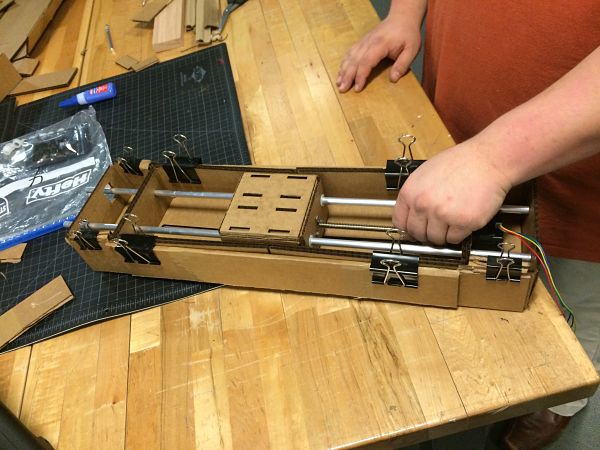

The first item I had to do was install the pygestalt framework. I cloned the library and then ran sudo python steup.py install.
The next item was to find and run an example to make sure the fabnet and the gestalt board are working. I found the simple single x axis example and ran it from the command line.

While testing the single x axis i tried to see the max range the axis could travel by increasing the position until the platform stalled at the end of the housing.
After a simple
a simple test I decided to hook up two axis
and try the x-y plotter code.

Once I knew
that it worked I read through the code and
started to change the speed with stage.xNode.setVelocityRequest(12)
line to see
how fast I could get the stepper motors to run.
This was about 16 in that function before it was too fast
and started to
skip.
If you have the axis move too fast the connection to the lead
screw will pop and the platform will not move or move very erratic.
After playing
with the speed I changed the code to find the max limits of travel and how to add more
paths to
the code. For the
final code we used the
single node code that imported a csv file that has some random moves to
make
the chimes seem more natural. We
also
found out the initial speed of 16 was too fast and we slowed it down to
12 and
the chimes sounded and ran better.

