15. Networking and Communications
Assignment
design and build a wired &/or wireless network connecting at least two processors
Lecture
broad
This time I would like make serial communication boards.
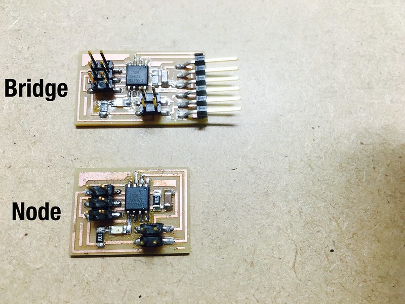
To make serial communicartion I need at least 2 boards Bridge and Node. I made one of hello.bus.45.bridge and 2 of hello.bus.45.nodes that Niel Designed. To make these boards I downloaded trace and interior png file from the text.
Then, use fabmodules to make RML file that Roland SRM-20 can manage. This process is documented on week4 assingment.
After making RML file, let's mill the PCB board.
bridge

node

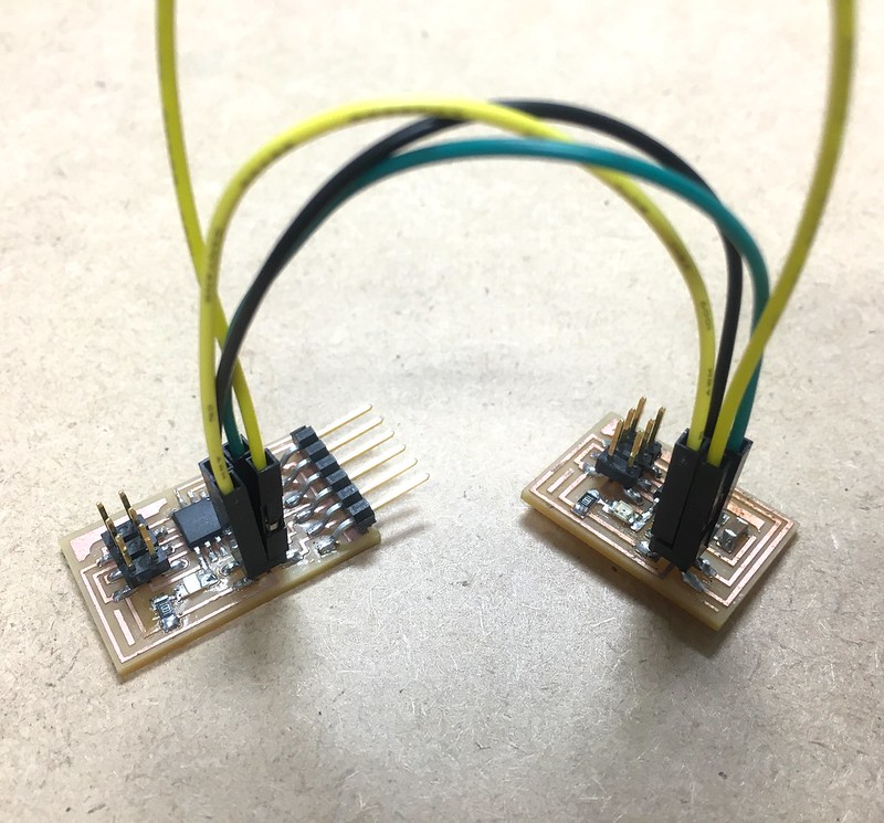
connection
Both boards Bridge and Node have 4 pins called BUS which have GND, V, Tx, Rx.
Connecting boards using these bus pins. The pin pairs are following:
GND to GND
V to V
Tx to Tx
Rx to Rx
Programming
It's time to write programs to Attiny45 on each boards. First, get the C file and Make file from the text.
The process of write program on Attiny is documented on week11 - Input Device
One important modification on C program is node_id. The default node_id is defined as 0 with following C code.
#define node_id '0'
Since each board should have unique id, I set Bridge board is node_is "0", and node is node_is "1".
To change the node id from 0 to 1, modify the following code like this way:
#define node_id '1'
Testing
To make serial connection, use term.py python program. If the everything is OK, the first boards's LED brinks 2times when you type "0" and second boards blinks 2times when you type "1".
Run the term.py program wiht following code with baud rate 9600:
python term.py /dev/tty.usbserial-FT94TOAV 9600