11. INPUT DEVICE
Assignment
Measure something: add a sensor to a microcontroller board that you have designed and read it.
Lecture
ATtiny45 datasheet
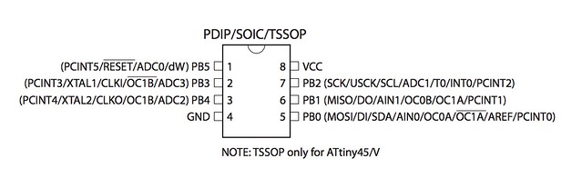
For this assignment ATtiny45 is used, so I read the ATtiny45 datasheet.
Here are the datasheet: Full[p234] / Summary [p30]
key notes:
- ATtiny45 only has Port B (6-bit bi-directional I/O port) and no Port A: PB0 ~ PB5
PB0 : MOSI
PB1 : MISO
PB2 : SCL
PB3 & PB4 : free to use
PB5 : RESET
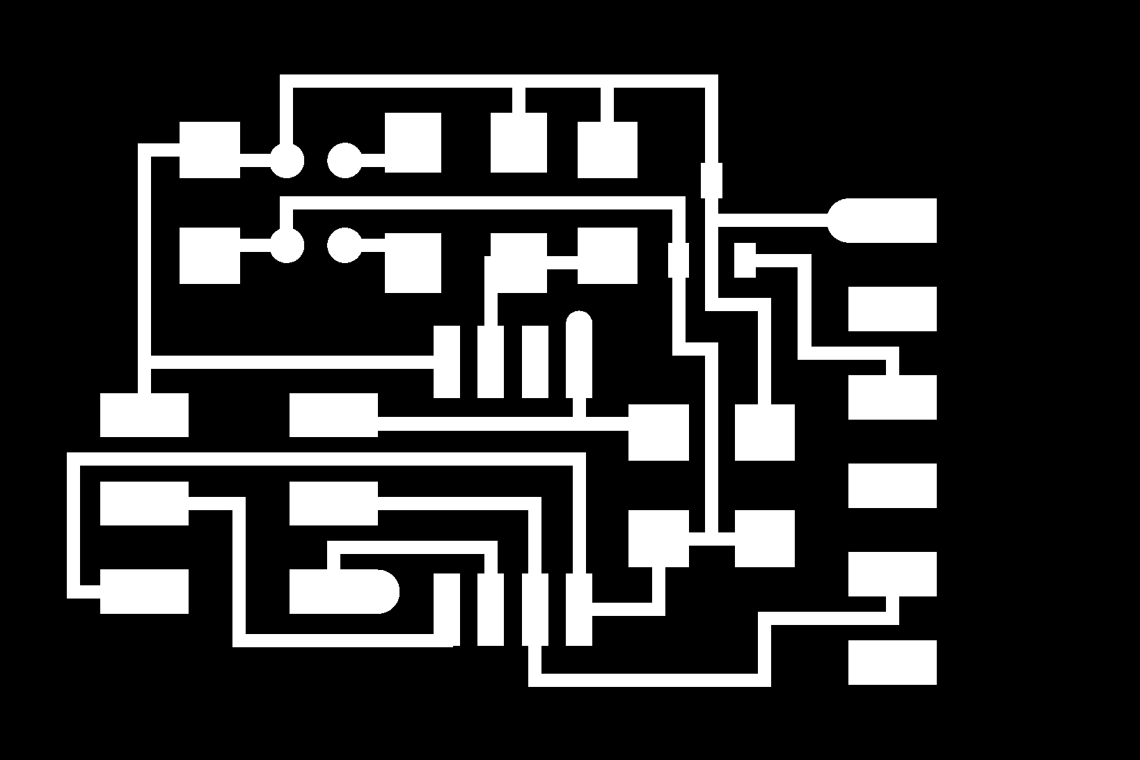
Board Making
I would like to make a sound sensor board MEMS analog microphone.
tools
milling machine : Roland SRM-20
endmill: 0.4mm & 0.8mm
PCB board
MEMS microphone :423-1134-1-ND
Attiny45
3.3v regulater
0.1uF capacitor x2
1uF capacitor
10uF capacitor
10kΩ resister
1kΩ resister
FTDI header(6pin)
2x3 pin
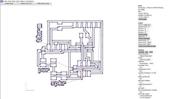
procedure
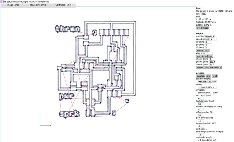
First, downloaded trace file and cutout file from INPUT DEVICE lecture website.
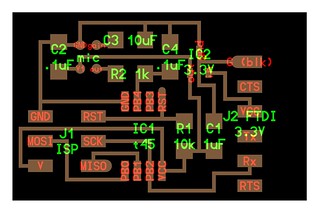
I modified the cutout png to make chamfer cut with PhotoShop because the edge was sharp.
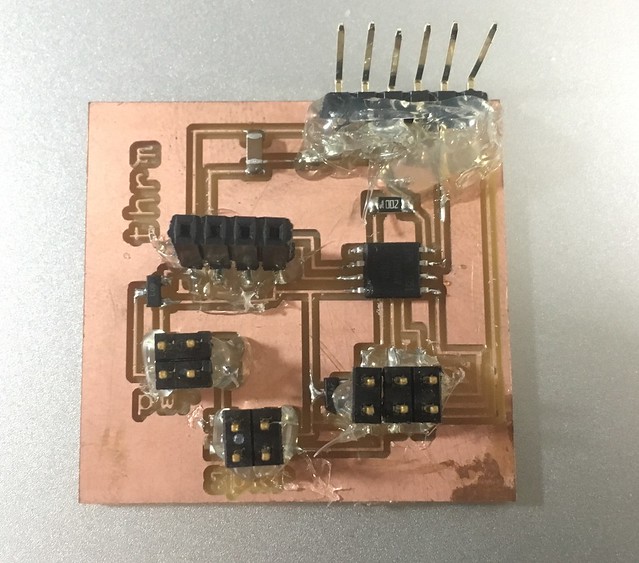
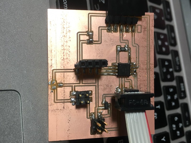
The tircky part was soldering MEMS microphone on the board without a heat gun. I tried to solder with soldering iron but it was not perfect attachement.
The microphone connection was not well but when I pressed it with my fingers it worked.
The final board looked like this:
Programming
connection
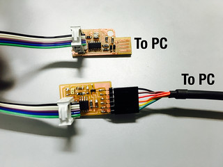
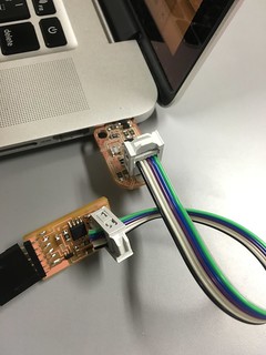
I connected FabISP which I made on week8 and input board with 2x3 wire. The FabISP was set to USB port of PC.
The FTDI was connected to USB port of PC via FTDI cable TTL-232R-5V.
sending program to board
C program file and Make file were downloaded
Opened Terminal and changed directory which had .c and .make file. then typed the comannds below:
XXX-no-MacBook-Pro:programming user$ make -f hello.SPU0414HR5H.make
                avr-gcc -mmcu=attiny45 -Wall -Os -DF_CPU=8000000 -I./ -o hello.SPU0414HR5H.out hello.SPU0414HR5H.c
                avr-objcopy -O ihex hello.SPU0414HR5H.out hello.SPU0414HR5H.c.hex;\
                	avr-size --mcu=attiny45 --format=avr hello.SPU0414HR5H.out
                AVR Memory Usage
                ----------------
                Device: attiny45

                Program:     558 bytes (13.6% Full)
                (.text + .data + .bootloader)

                Data:        201 bytes (78.5% Full)
                (.data + .bss + .noinit)

XXX-no-MacBook-Pro:programming user$ sudo make -f hello.SPU0414HR5H.make program-usbtiny-fuses
                Password:
                make: *** No rule to make target `program-usbtiny-fuses'.  Stop.

XXX-no-MacBook-Pro:programming user$ sudo make -f hello.SPU0414HR5H.make program-usbtiny
                avr-objcopy -O ihex hello.SPU0414HR5H.out hello.SPU0414HR5H.c.hex;\
                	avr-size --mcu=attiny45 --format=avr hello.SPU0414HR5H.out
                AVR Memory Usage
                ----------------
                Device: attiny45

                Program:     558 bytes (13.6% Full)
                (.text + .data + .bootloader)

                Data:        201 bytes (78.5% Full)
                (.data + .bss + .noinit)


                avrdude -p t45 -P usb -c usbtiny -U flash:w:hello.SPU0414HR5H.c.hex

                avrdude: AVR device initialized and ready to accept instructions

                Reading | ################################################## | 100% 0.00s

                avrdude: Device signature = 0x1e9206
                avrdude: NOTE: "flash" memory has been specified, an erase cycle will be performed
                         To disable this feature, specify the -D option.
                avrdude: erasing chip
                avrdude: reading input file "hello.SPU0414HR5H.c.hex"
                avrdude: input file hello.SPU0414HR5H.c.hex auto detected as Intel Hex
                avrdude: writing flash (558 bytes):

                Writing | ################################################## | 100% 0.49s

                avrdude: 558 bytes of flash written
                avrdude: verifying flash memory against hello.SPU0414HR5H.c.hex:
                avrdude: load data flash data from input file hello.SPU0414HR5H.c.hex:
                avrdude: input file hello.SPU0414HR5H.c.hex auto detected as Intel Hex
                avrdude: input file hello.SPU0414HR5H.c.hex contains 558 bytes
                avrdude: reading on-chip flash data:

                Reading | ################################################## | 100% 0.66s

                avrdude: verifying ...
                avrdude: 558 bytes of flash verified

                avrdude: safemode: Fuses OK (H:FF, E:DF, L:62)

                avrdude done.  Thank you.
visualization of input
I used a python program from here.
I checked the name of USB port with this command:
ls /dev/tty.usb*
Run python program:
python hello.SPU0414HR5H.py /dev/tty.usbserial-FT94TOAV
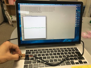
video
Another Input & Output Board Designing
concept : Theramin with distance sensor & speaker
Next, challenge is to make one board with input and output.
So the idea is that conbining the 2 board in 1.
The concept is Theremin with following input and output:
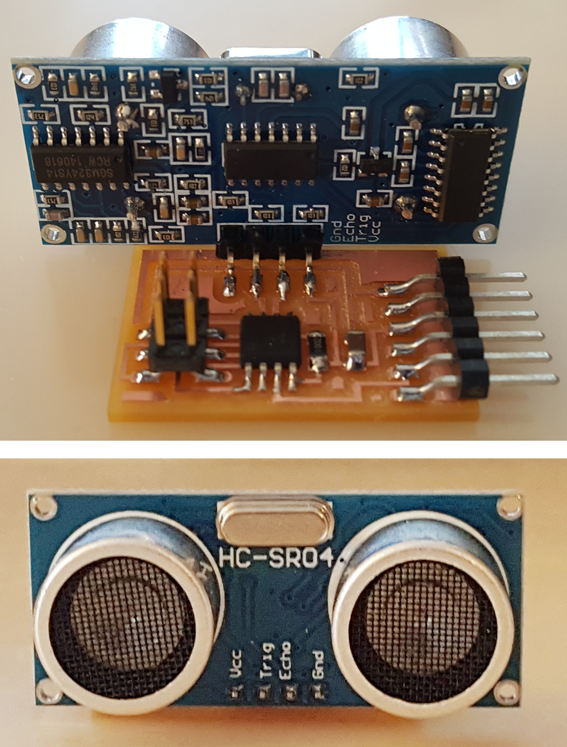
[input] : distance sensor
[output] : speaker
This is Theremin:
Board Design
To design the Theremin board, I combied following 2 boards which were designed by Neil.
[input:distance]
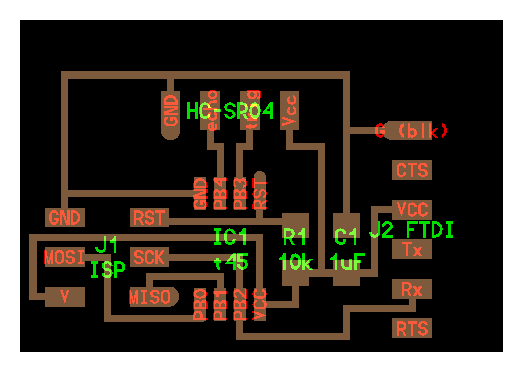
[output:speaker]

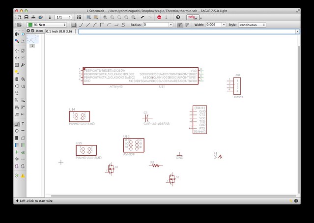
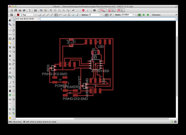
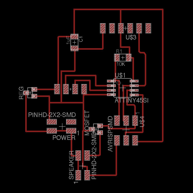
Designing the board with Eagle
Opened Eagle and added the all parts in schematic.
There were some notes:
- NDS355AN(N-channel MOSFET) : This was not found in Eagle library first. After internet research, "MOSFET-NREFLOW"(SOT23) can be used as NDS355AN.
- LM3480 : 5V regulator that is also SOT23 type.
- one ATTiny45
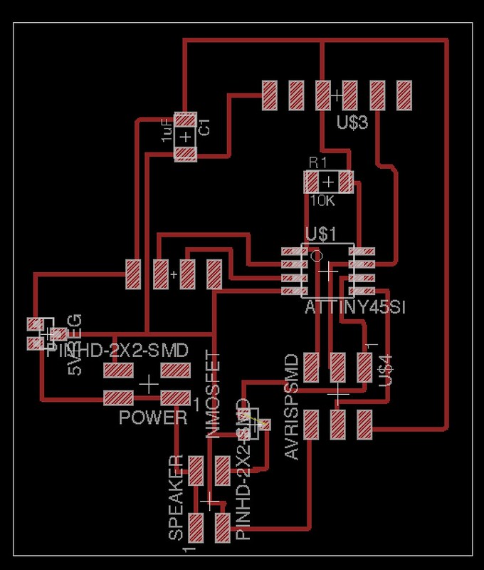
Then, I named and connected all parts.
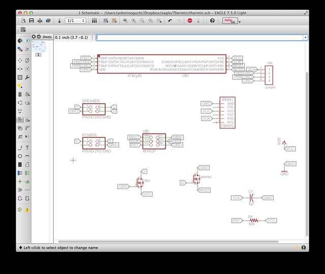
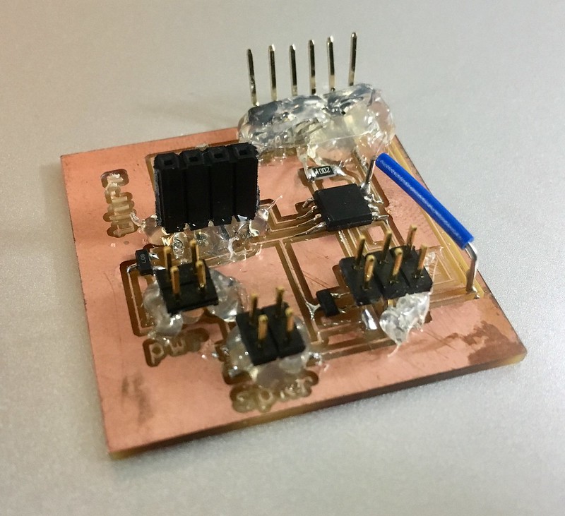
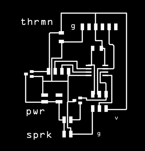
Here the board board design.
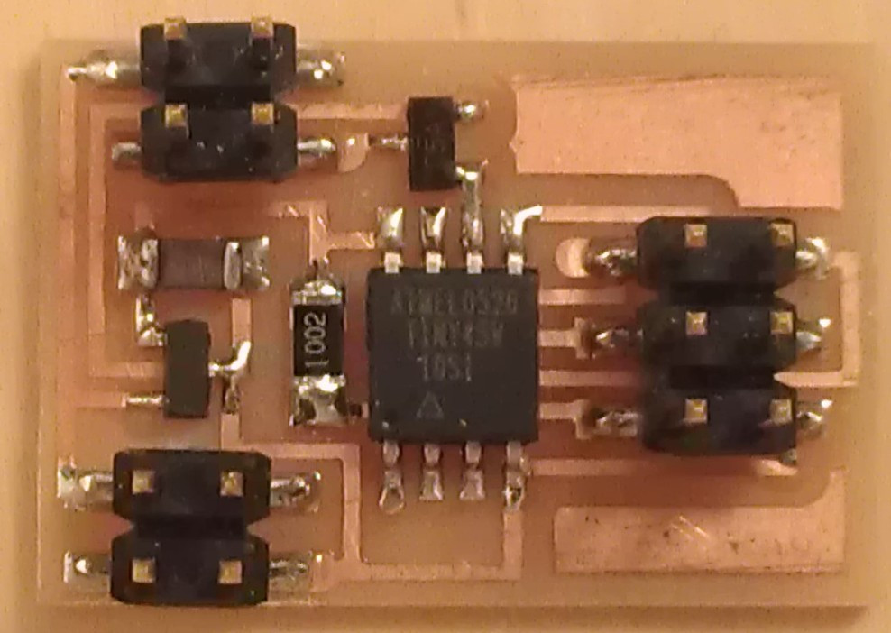
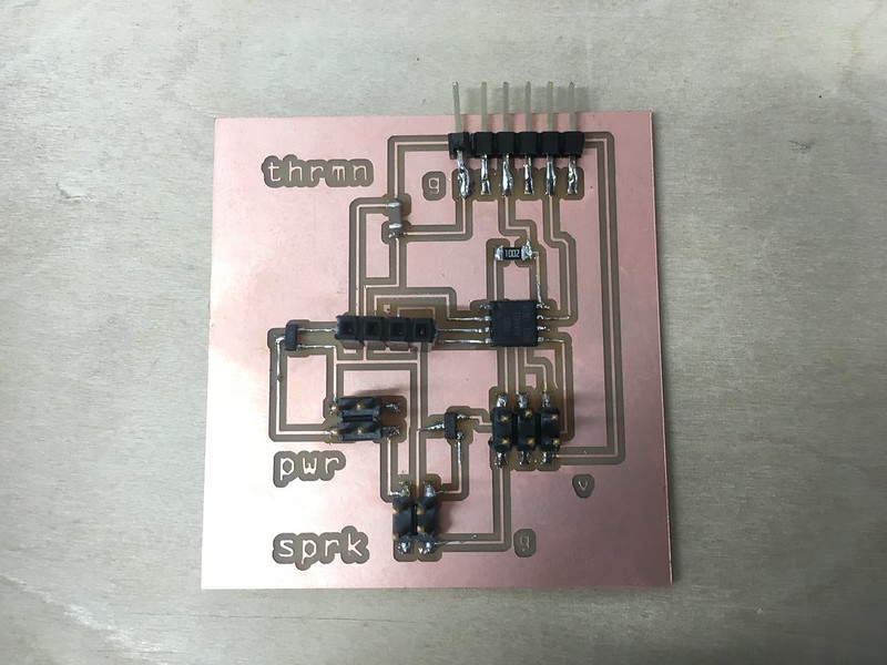
after milling and soldering
I soldered all parts, then I put the glue for the stronger attachments of parts.
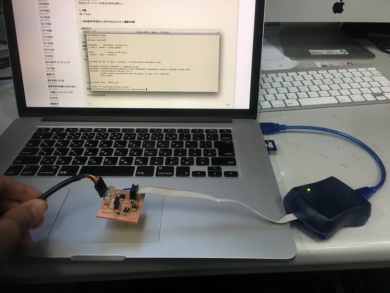
TROUBLE: can't write program
When I connected the board with AVR writer, the green LED on the the AVR writer was on. It indicated that the connection was fine. However, I couldn't write program to the board. I checked the all connections on the board with a multimater and found a missing connection. I added a bridge(the blue wire on the picture). And I tried to write the program again, but still it didn't work.
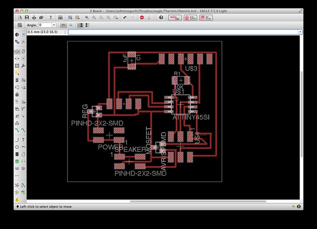
re-layout and remake the board
I suspected that the board wires were too close, so I changed the layout with more spaces. These were the 2nd board layout. But it didn't work.

The 3rd board
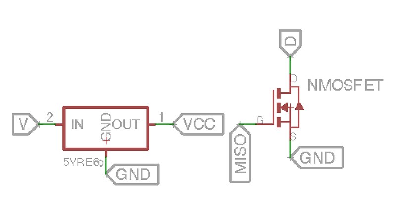
I re-checked the schematic on Eagle, and found that the regulator and MOSFET parts were wrong.
I missed the MOSFET and regulator in the Fab library on the Eagle and the parts I chose had different layouts of IN/GND/V and MISO/D/GND. That was the cause of mistake.
So,I replaced the 2 parts and re-layout the board again.
Trouble: smokey regulator
I remake the board. This was the 3rd version.
When I connected the FTDI cable, the regulator became really hot with smoke.
The cause of the problem was that the regulator was designed for battery use, not the power from the FTDI. In this board, the FTDI Vcc is connected OUT of is regulator connected. That connection made the regulator burned.
So, I took the regulator out from the board, then wrote the program. That was no problem.
Video
This is the outcome video when it had the program for HC-SR04 distance sensor.