| Home | | Weekly Assignments | | Final Project | | Photo Gallery |

Week 6: Electronics Design
Assignment
This week's assignment is to re-draw echo hello world board and add an LED and a PUSH button it. Designing can be done using Eagle, Kokopelli 123D circuits etc. Francisco taught us Kokopelli during prefab training. Before drawing with kokopelli, I am giving Eagle a try.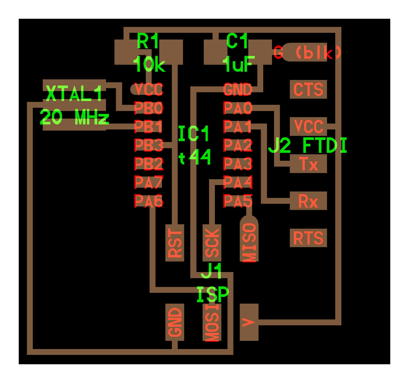
EAGLE
EAGLE(Easy Applicable Graphical Layout Editor) is flexible electronic design automation (EDA) application with schematic capture editor, printed circuit board (PCB) layout editor and auto-router. I downloaded Eagle on Ubuntu and opted for the freeware option.
Then to add the required library, I downloaded fab.lbr from fab academy, electronics design page. I located the library folder of Eagle and moved fab.lbr to that folder using terminal.

For designing the echo hello world board in Eagle, I opened eagle created a new schematic file. The following components needs to be added.
- ATtiny44
- FTDI 6 pin connector
- 2x3 Connector
- Capacitor
- Resistor
- Resonator
- LED
- Press button
- Ground
- Button

Components can be added by clicking the add button on the left tool bar and choosing the components from the drop-down menu. Now that I've got a basic idea how eagle works, I decided to complete this assignment(add a button and LED to Neil's board) using Kokopelli.
KOKOPELLI
Kokopelli is an interesting software developed by Matt Keeter for designing electronic circuit boards through code.
Kokopelli Installation
Downloaded koko_retro.zip file(link).
Then I installed the dependencies for python using the following command.
sudo apt-get install python python-wxgtk2.8 python-dev python-pip gcc g++ libpng12-dev libgif-dev make bash okular libboost-thread-dev libboost-system-dev cmake
Then I used the following command to install numpy
sudo pip install numpy PyOpenGL PyOpenGL_accelerate
Then I unzipped koko_retro.zip to a folder. Used the following commands on terminal
- make clean
- make fab
- sudo make install
- and then to launch the program: kokopelli –r
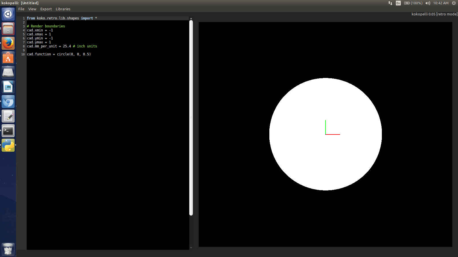
Now kokopelli is up and running fine on Ubuntu.
Next thing I need to do is to add an LED and a button to Neil's Hello.ftdi board. The files in kokopelli are save in .cad format.
First I need to open the hello.ftdi cad file made in Kokopelli. Interestingly Prof. Neil has created an inventory of electronic components inside this 4000 line code. In order to add components into the design, the name of the classes(code snippets)can be copied reused multiple times to modify and create better and more complex boards.
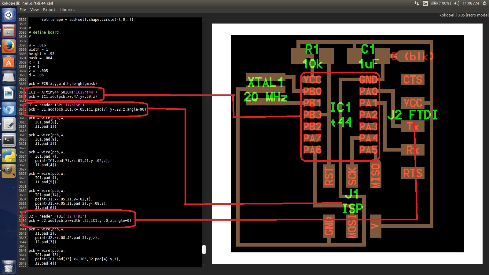
I opened hello.ftdi.44.cad (file link) on kokopelli. The right side shows the preview of the board and the left side coloumn is the code editor.
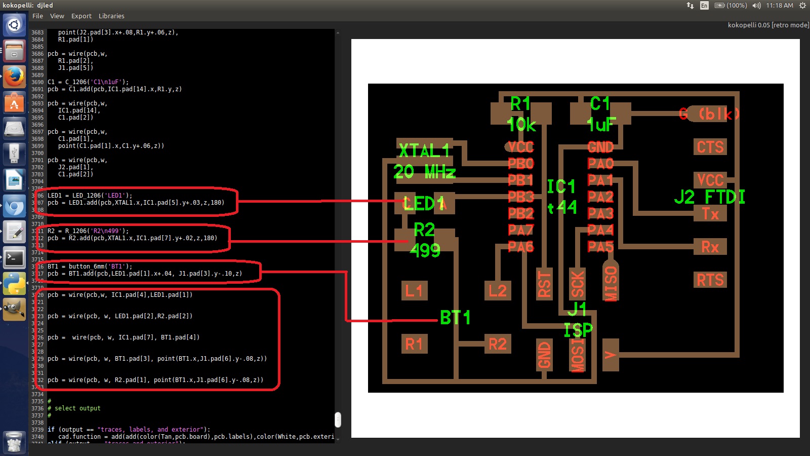
First I increased the width and height of the board to 1.25 and .93 respectively by making changes in the code to accomodate and LED and button. Then, I added an LED, a 499 ohm resistor and a button and wire connections for the same to the board by adding following code.
LED1 = LED_1206('LED1');

pcb = LED1.add(pcb,XTAL1.x,IC1.pad[5].y+.03,z,180)


R2 = R_1206('R2\n499');

pcb = R2.add(pcb,XTAL1.x,IC1.pad[7].y+.02,z,180)


BT1 = button_6mm('BT1');

pcb = BT1.add(pcb,LED1.pad[1].x+.04, J1.pad[3].y-.10,z)


pcb = wire(pcb,w, IC1.pad[4],LED1.pad[1])

pcb = wire(pcb, w, LED1.pad[2],R2.pad[2])


pcb =  wire(pcb, w, IC1.pad[7], BT1.pad[4])

pcb = wire(pcb, w, BT1.pad[3], point(BT1.x,J1.pad[6].y-.08,z))

pcb = wire(pcb, w, R2.pad[1], point(BT1.x,J1.pad[6].y-.08,z))
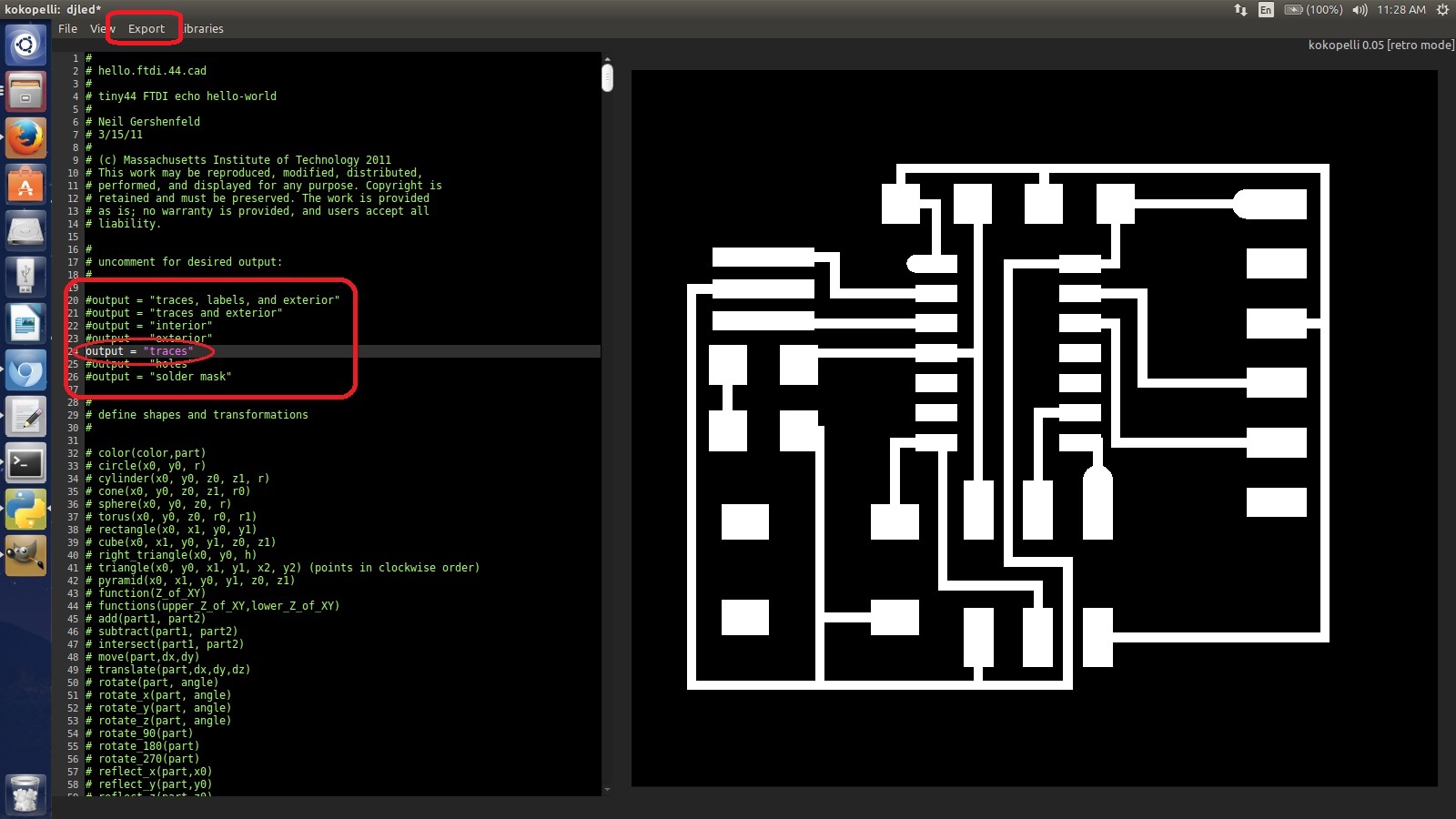
To sucessfully mill this board using Roland Modella, I need to export the png of the traces(for milling) and interior(for cutting the board). To do that, I need to go to the top part of the chord and take off the # from 'traces' to uncomment it. This will show the traces alone as preview and then I can easily export it as a png file using the export option on the top part of the window.
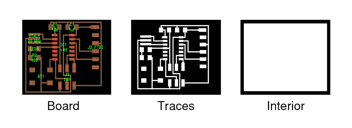
Once I exported the png file for traces, I uncommented 'interior' and then exported a png file which can be used to cut the outline of the board on milling machine. I kept the layer resolution as 40 while exporting these png.


Now I have png files for traces and exterior with which I can mill the board on Roland Modella.

The board with the same design file produced on Modella.
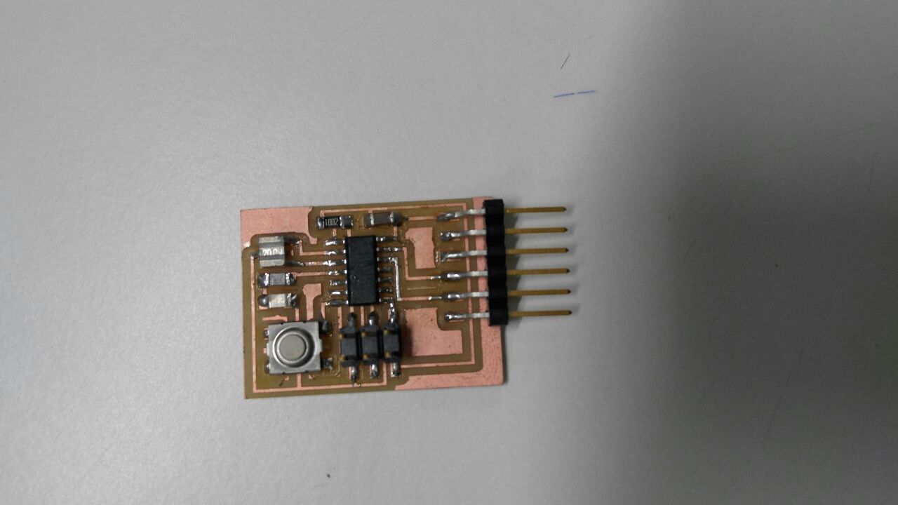
Final board with added button and LED after stuffing the components.
Files:
djled.cad djledtraces.png
djledinterior.png