| Home | | Weekly Assignments | | Final Project | | Photo Gallery |

Final Project:Seeya (Electronic mouse trap)
After shuttling between a few ideas for the final project, I decided to stick with a rather simple project which I can do from scratch by making use of almost all the equipments available in FabLab.
I have a phobia for rats and I occasionally have to deal with rat problems at the store room of my house. We have a large 100 year old abandoned kerala-style mansion next to my house which is home to at least a dozen of rats. No matter how much we try to get rid of rats, some rats still seems to figure out some way to migrate from there to the store room of my house.
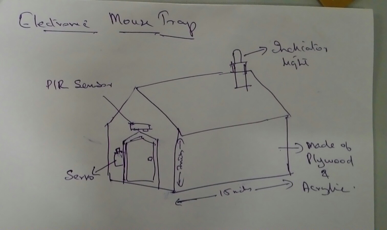
I am hoping to find a solution to this problem by building an electronic mouse trap during my Fab Academy period. The final product is expected to look like a cute portable mini-dog house. And this cute little thing will trap rats/mouse. No mice shall be hurt/killed with this device. This device is meant only to trap rats. More details about the project including 2D and 3D designs of the same shall be updated in the coming days.
Unlike conventional mechanical mouse trap, This mouse traps uses a PIR sensor which detects the motion of the mouse inside and triggers the door closure with the help of a servo motor. I am looking forward to implement most oof the things I learned in Fab Academy while doing this project. I am planning on completing this project by including the followin processes.
- 2D and 3D Designing
- 3D Printing
- CNC cutting
- Laser cutting
- Electronics Production
- Embedded Programming
- Vinyl Cutting
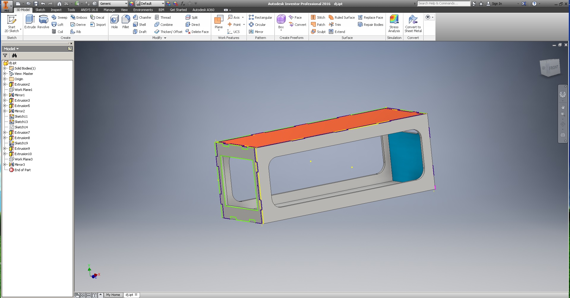
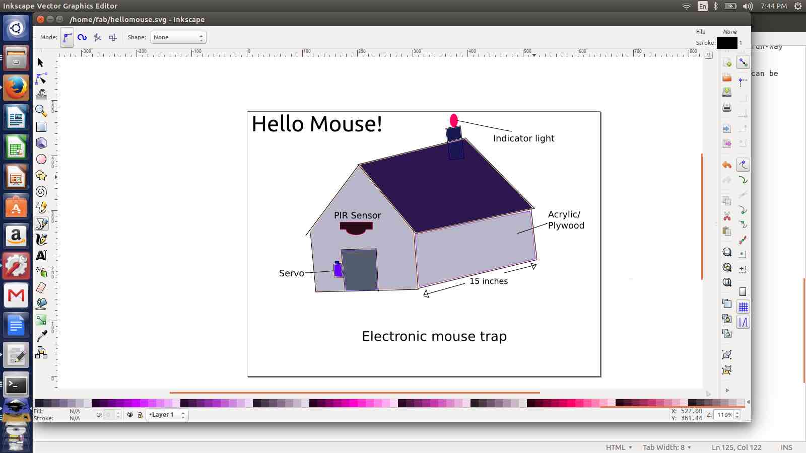
I made a few changes in the design I drew by hand and in Inkskape. This time I used Autodesk inventor to design the basic structure of my mouse trap.
I focused on making the case look a bit more neat. Now it doesnt look like a house, but the looks are more closer to a product that comes out from a factory.
LASER CUTTING - To get an idea how the actual product would look like
As soon as I finalized this design, Instead of keeping a window grill, I decided to keep transparent acylic sheet as the window part. To make sure that this design looks good, Instead of cutting the plywood on shopbot cnc, I decided to laser cut the desing on cardboard just to get a feel of how it looks.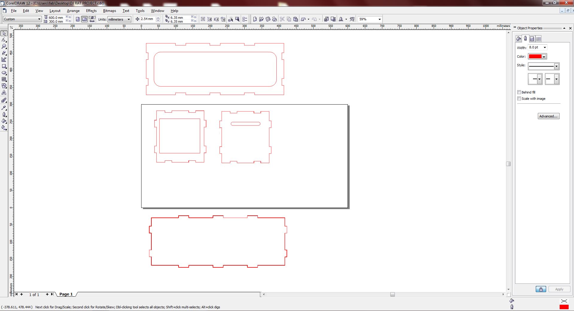
So 2D design for the press fit was exported and I opened the same in Corel draw on the system attached with our laser cutter.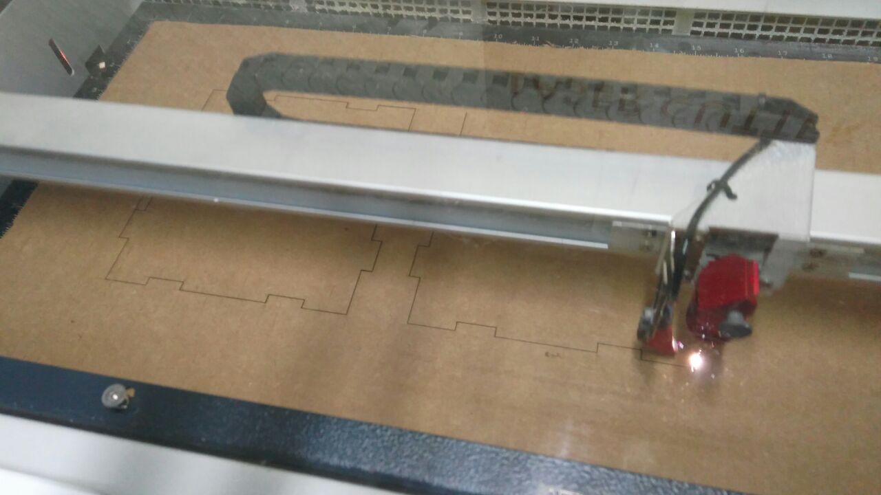
I cut the press fit parts on Trotec Speedy 100 laser cutter.
Now its just a matter of joining the puzzles to get a feel of how the actual product would look like.
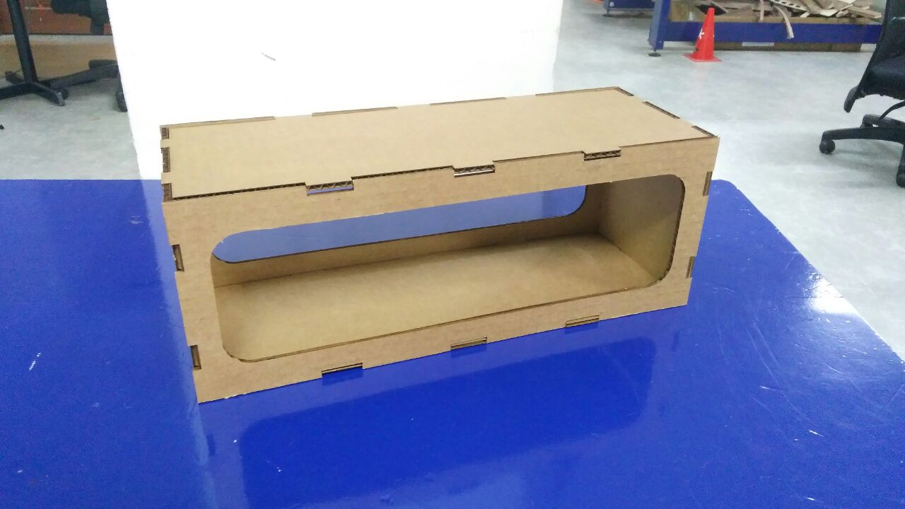
The outer casing should look the same way once plywood is cut on shopbot. This is exactly what I wanted. So, I'll go ahead with the plywood cut on shopbot cnc.
CNC CUTTING - Cutting the actual plywood product case.
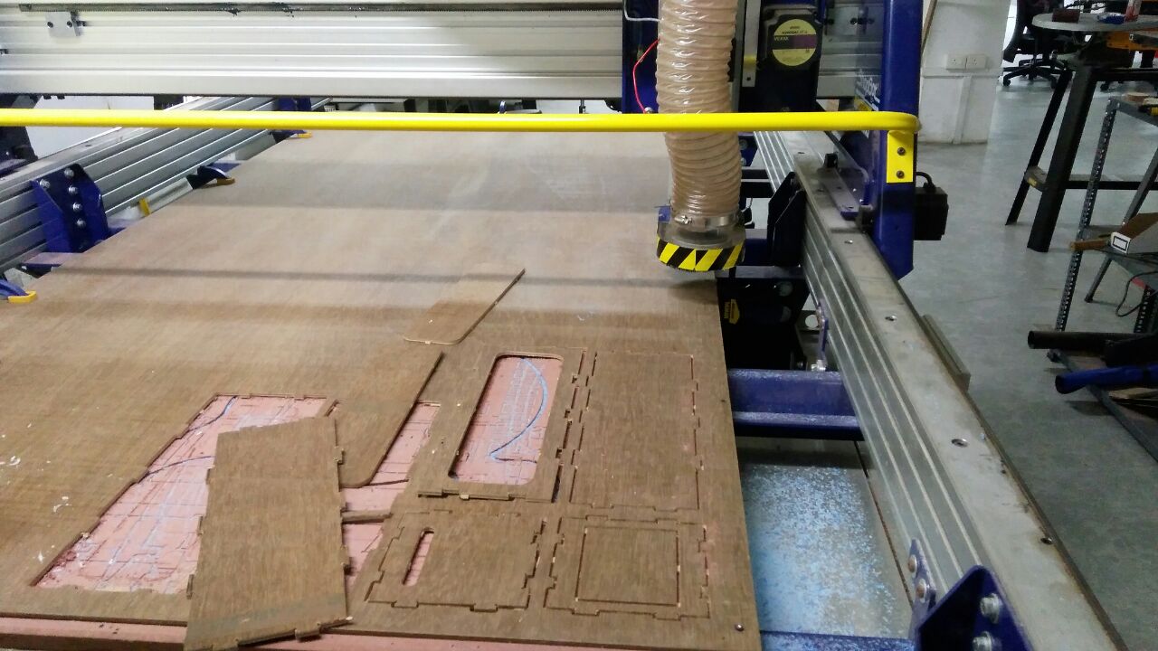
Cut plywood on shopbot CNC. I removed the taps with a chisel.
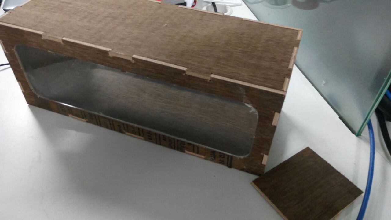
Joined the press fit using a mallet. It press fit holds firmly and is strong enough even to catch a large mouse. :)
LASER CUTTING - Cutting windows of mouse trap
Next, I need to add transparent window to my mouse trap. For this, I am using 6mm clear acrylic sheet. I took the window measurements from the same design and cut the window part on Trotec laser cutter.
For cutting, I set the power at 90% and speed at 2% on laser cutter.
The window panels came out clean after the cut. I fixed it to the sides of the mouse trap and sticked the internal edges using glue gun.
3D Printing - Adding a handle to make the mouse trap portable
The mouse trap I am designing is meant to be portable. This trap only traps the mouse and does not kill. So it is very important to have a good handle to carry it around. The idea is to design a good looking handle, 3D print the same and fix it on the mouse trap.
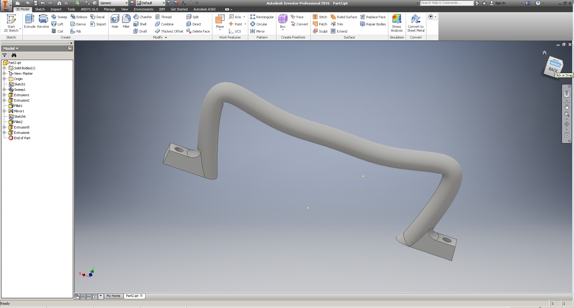
I exported the STL from Autodesk Inventor. We have two 3D printers at FabLab. Ultimaker 2 which prints with PLA material and Dimension elite 1200ss which prints in ABS material.
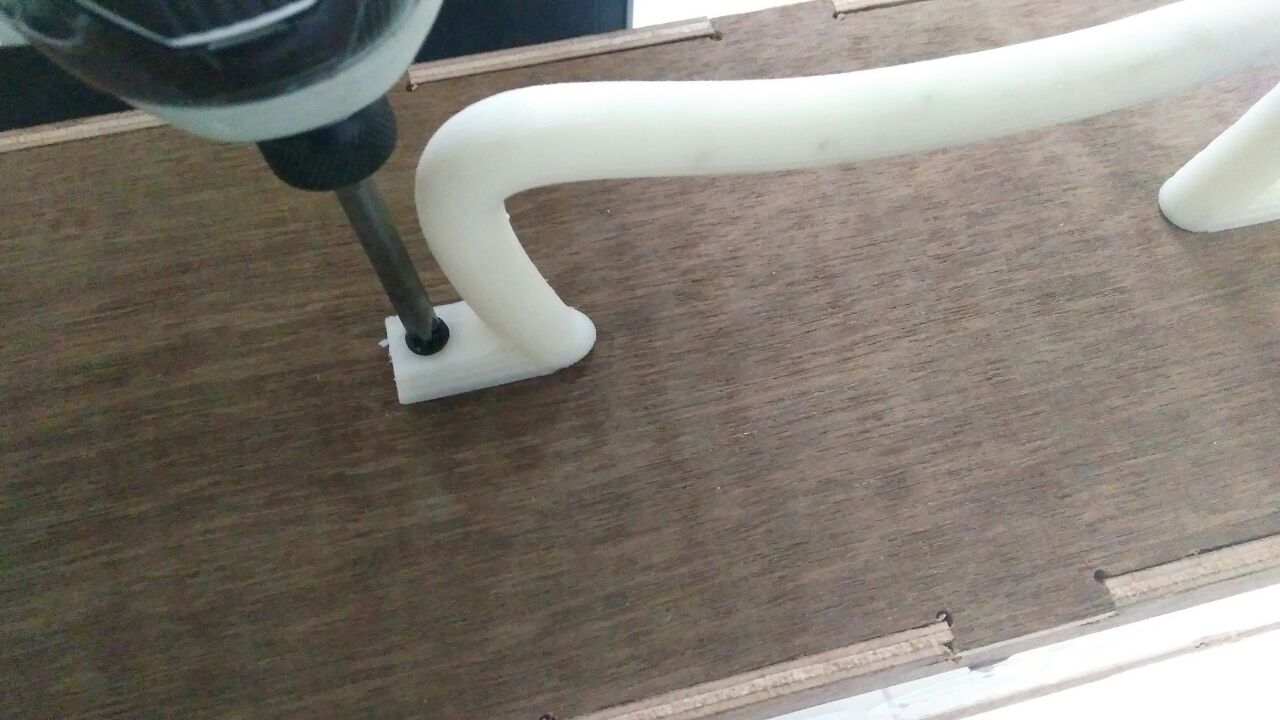
As I wanted a handle with better finish, I decided to print the handle in Dimension elite 1200es.
I opened the stl file in Catlyst software and set interior as high density and added pack. It took a couple of hours to print this particular piece and after immersing it in the chemical bath for almost 8 hours, It looked neat.

I fixed the handle on top of the mouse trap with the help of screws.
The door for the mouse trap was by laser cutting transparent 6mm acrylic sheet and I added a few white vinyl stickers to make it look good. I sticked the servo and the door to the trap using glue gun.

ELECTRONICS DESIGN AND PRODUCTION - PIR sensor and Servo.
Whenever I want to make a board for some particular purpose, I start by modifying Neil's board as its already a versatile boards capable of performing many tasks if its modified correctly. Here I wanted to add a PIR sensor to the board and also connect a servo to it. So whenever a mouse enters the tap, the PIR sensor detects motion and triggers the servo to close the door.
What is a PIR sensor?
PIR passive infrared sensor (PIR sensor) is an electronic sensor that measures infrared (IR) light radiating from objects in its field of view. They are most often used in PIR-based motion detectors and here I am using it to detect a mouse inside my mouse trap. So I modified Niel;s board in such a way that PIR sensor is conncted to three pins on the board. ground, vcc and signal.
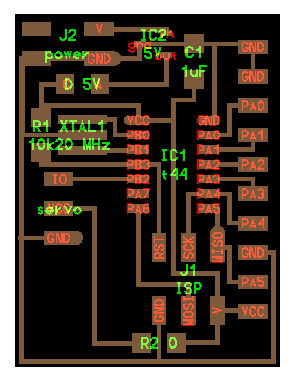
The above image shows the outcome of the modifications I made in Neil's board. Now it has a PIR sensor and servo added to it.

The board was milled using Roland Modella MDX20 and stuffed at the elctronics workbench and the following image shows how it looks like.
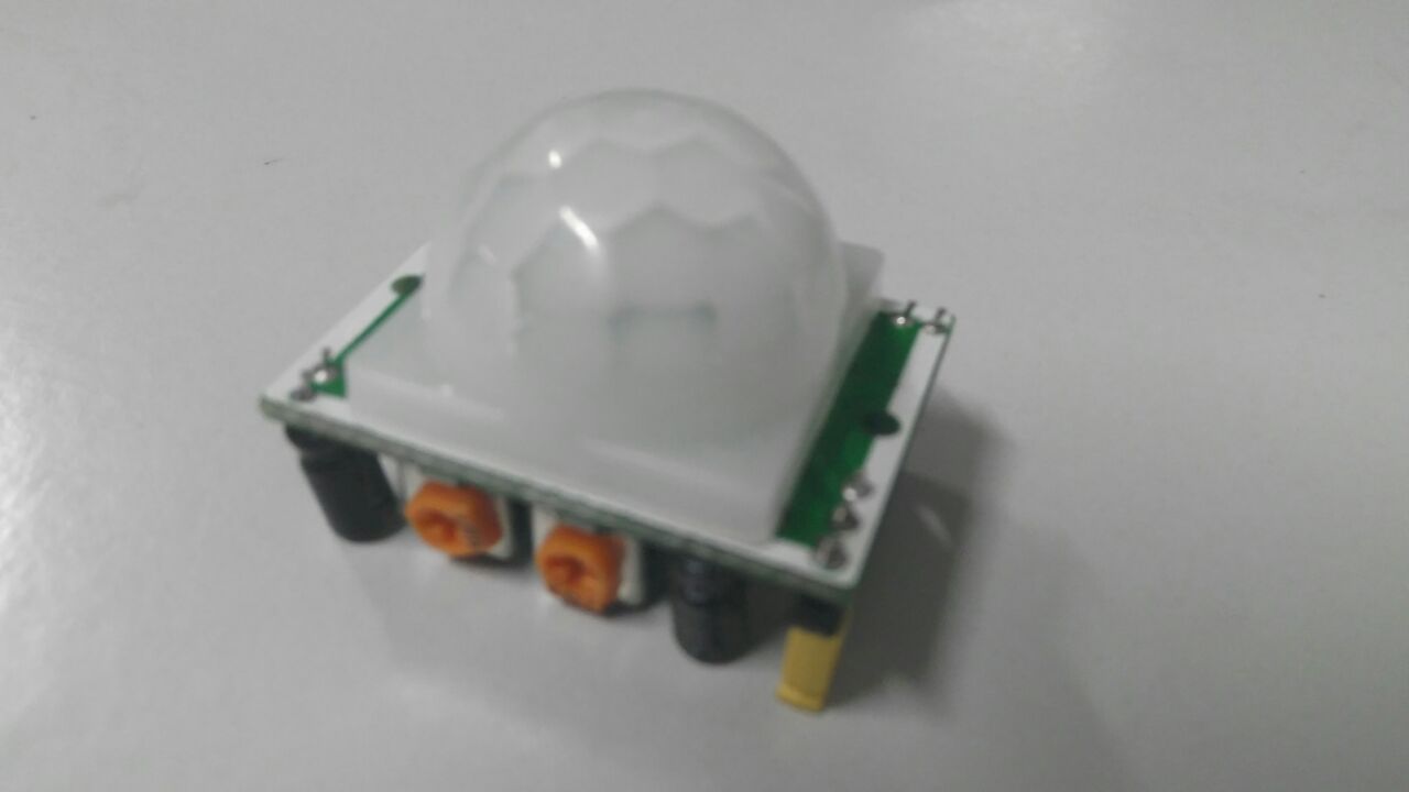
I purchased a PIR sensor from a local electronic shop and it costed on Rs. 140.
Now I have connected the PIR and servo motor to the board.
Whenever PIR sensor detects motion the signal pin becomes high and I need to do arduino programming for Niel's board in such a way that the servo works when PIR signal is high. To get this done, I used the code below.
int Pir = 5;
#include

Servo myservo;

int pos = 0;


void setup() {

  pinMode(Pir, INPUT);
  myservo.attach(8);
}


void loop()
  {

  for(pos = 0; pos < 120; pos += 1)

  {
    myservo.write(pos);
    delay(25);
  }
  for(pos = 120; pos>=1; pos-=1)
  {
    myservo.write(pos);
    delay(25);
  }


               // Reads if PIR input is high or low
  if (Pir == HIGH)
  digitalWrite (myservo, LOW);
        //
  else for(pos = 0; pos < 120; pos += 1)

  {
    myservo.write(pos);
    delay(25);
  }
  for(pos = 120; pos>=1; pos-=1)
  {
    myservo.write(pos);
    delay(25);
  }

  }
}
Probelms faced
On testing the above code with the board, the servo was only vibrating inside while the PIR detects motion, However, while running the program on an Arduino board it was working fine. I tried making some modifications in the code just to get the servo moving properly. I was able to test servo movment finally without any problem.
Testing servo action
Once I was able to get the servo to move, I used the code mentioned previously in this same page to open the door whenever the PIR sensor detects motions.
Now that the mouse trap's electronics and mechanicals are working fine now, Its time to make it look good.

I've decided to brand the mouse trap as 'Seeya'. So I desinged a the brading on an online desing tool "Canva"

Then I used the Rolan vinyl cutter to cut a sticker of the same design.
This is how the final Product looks like:

Files:
CNC cutting & 3D printing
dj3ddesign.ipt
djhandle.ipt
Electronics production
djpro.png
djprotraces.png
djprointerior.png
Embedded Programming
djprocode.ino
Laser cutting
djsides.dxf
djtop.dxf
djsides.dxf
Vinyl cutting
seeyas.png
Bill of Materials
I made this project by ensuring that I make use of the consumables and components available at our FabLab invnetory before buying any other components from shops outside. 95% of the materials and components are taken from FabLab inventory and I had to buy only a PIR sensor from outside. I am adding the things used from FabLab inventory and their cost in Indian Rupees.
Mechanical Parts
- 3mm Plywood for external case : 2ft x 2ft (FabLab Inventory)
- 3mm Clear transparent acrylisc sheet : 30cm X 60cm (FabLab Inventory)
- Small copper clad laminate circut board(FR1) for pcb: 1 (FabLab inventory)
- ATtiny33 microcontroller: 1 (FabLab Inventory)
- Resistor 10K: 1 (FabLab Inventory)
- 5V Voltage regulator: 1 (FabLab inventory)
- 20 Mhz Resonator:1 (FabLab Inventory)
- Capacitor 1uF:1 (FabLab Inventory)
- 2x2 pin header:1 (FabLab Inventory)
- 2x3 pin header:1 (FabLab Inventory)
- 0 ohm resistor:1 (FabLab Inventory)
- 1x10 pin connector: 1 (FabLab Invetory)
- PIR sensor: 1 (Local electronic shop Rs. 140)
- ABS Model Material(FabLab inventory)
- ABS Support material(FabLab Inventory
- White vinyl sticker 30cmX 15cm: 1
Total cost of this project:
Rs. 780
Project Video
Project Slide
