Week 13: Output Devices
Homework for this week:
- Add an output device to a microcontroller board you've designed and program it to do something.
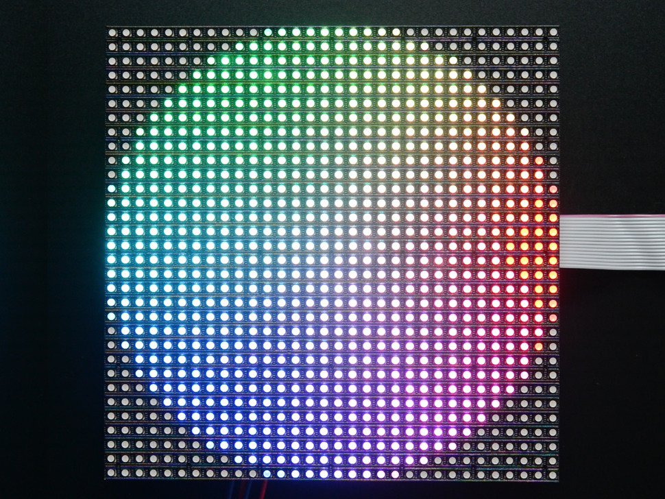
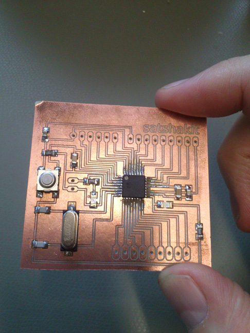
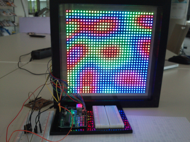
For this assignment I made an Arduino Uno compatible Satshakit and attached a 32x32 RGB LED matrix to it that I bought from here. I also successfully tested it with my VGS board that I made for my final project. The matrix panel comes ready with libraries and can be attached to either an Arduino Uno or an Arduino Mega 2560. (In my final project I have made it work with an ATmega1284p.)
How to mill a nice Satshakit and then (nearly) botch it up
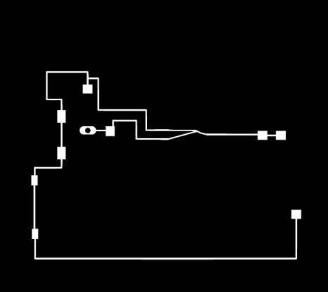
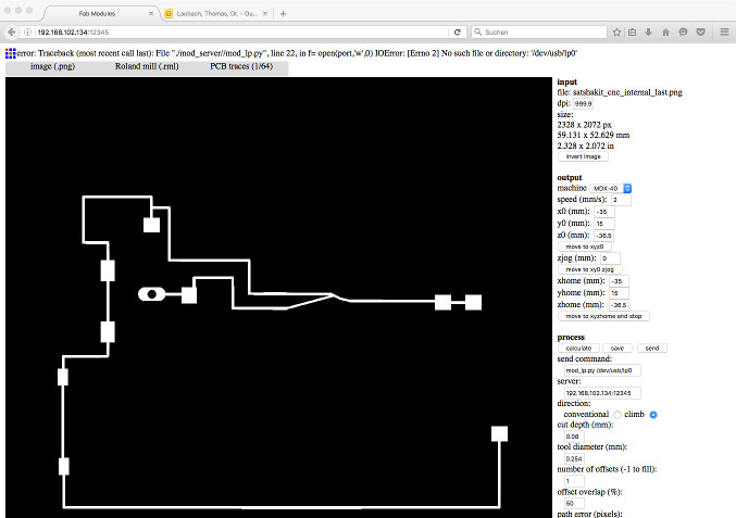
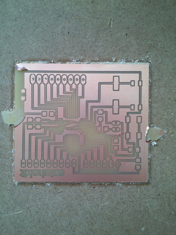
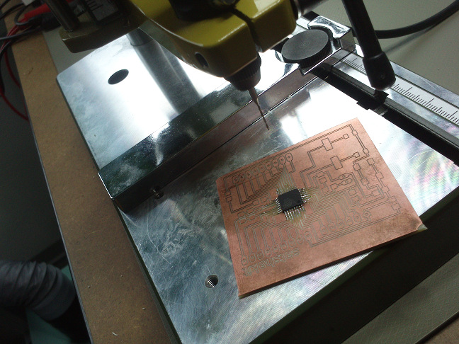
With the process used in the assignment on input devices I milled a Satshakit on our Roland MDX-40A mill. In the first run, I got a board that was not milled uniformly everywhere, although I had fixed it to the plate with screws. I underwent a second try, but this time fixing the copper plate with double-sided tape on the plate. I got a perfectly milled Satshakit. What follows are some impressions of the preparations with the FabModules prior to milling. The halftone images were made with GIMP, using the operations "thresholding" and "fill with foreground color".
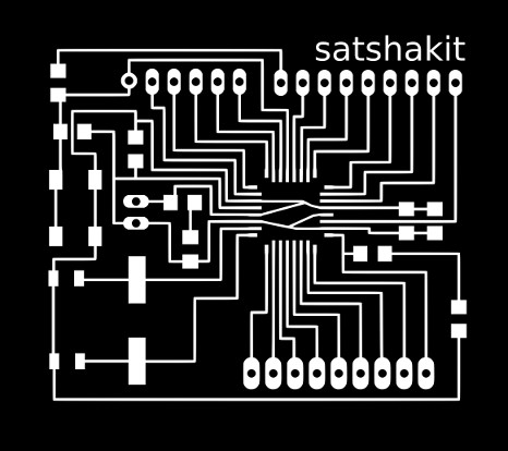
Contrary to the two-stage process used for milling my Shrunken Micro board from week 11, a third stage that involves drilling holes is necessary for the Satshakit. With our machine this requires changing the milling tool.
Some parts of the traces at the periphery were too shallow and needed to be milled anew. For this it was necessary to delete the parts of the board that did not need re-milling. For the border, an other template was needed. The "bridges" in the border shall make it easy to remove the board from the copper plate.

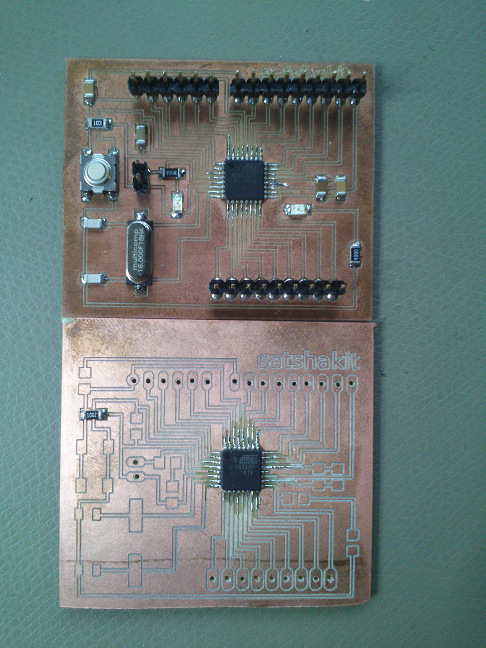
Disaster struck when I tried to carefully remove the Satshakit from the plate with a screwdriver. I screwed up and damaged the board. Although nasty to look at, the Satshakit does electronically work. As I am a little late, I will use this Satshakit for the forthcoming assignment on networking, despite of its looks.
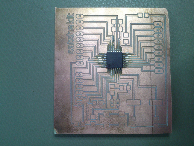
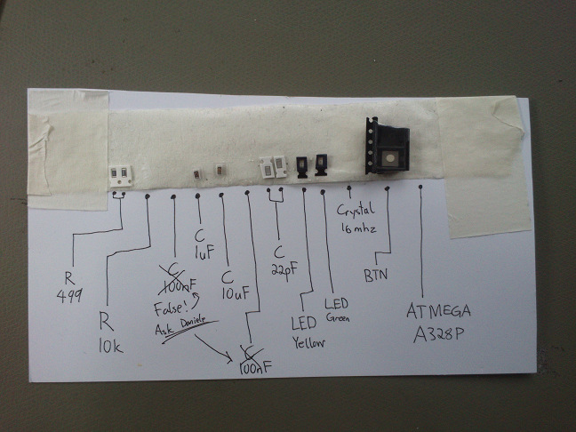
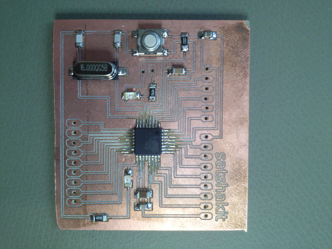
For this assignment, I soldered the components instead to another Satshakit board that I have fabricated - just to play safe. For some impressions of the soldering process, please see the following pictures.
I hoped I would be able to burn the boot loader onto the Satshakit without having pin headers soldered to the board. This approach failed because the Satshakit was not found by the Arduino IDE. I will try again when I have added the pin headers to the board.
Next day: After adding the pin headers, the Satshakit worked. Obviously, the pins did not make electrical contact to the traces.
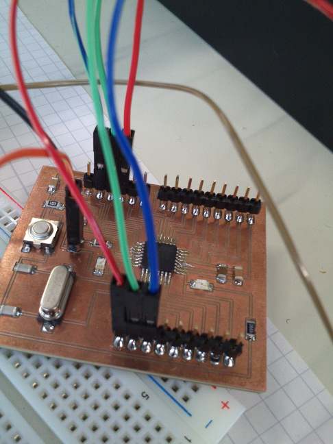
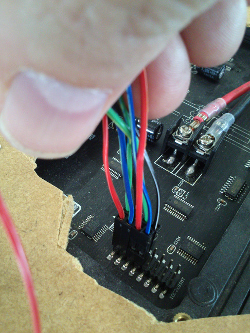
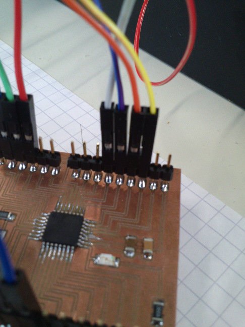
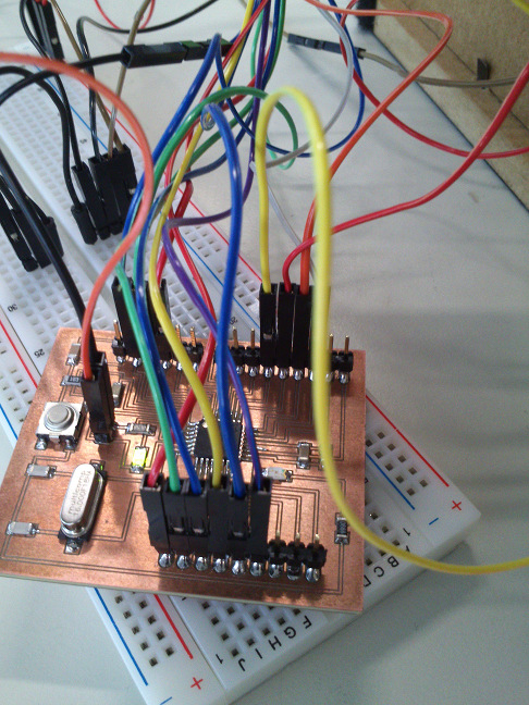
Connecting the LED matrix and the Satshakit
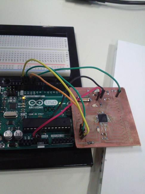
For testing purposes, I wired the LED matrix panel to several devices: an Arduino Uno, my Satshakit that was milled on a laser cutter, and a Sathshakit that was milled on our Roland MDX-40A mill. Additionally, I used two different LED matrix panels, one that I had already used in another device, and another that I had ordered some time ago. My LED matrix panels are from here. I have also tested one with smaller pitch that had the RGB channels in a different order. All matrices work with the Arduino Uno and the Arduino Mega 2560 only.
Using the LED matrix panel required me to jump through some hurdles:
- connecting Arduino and LED matrix correctly (16 cables plus connector),
- plug in the FTDI cable additionally and use GND and PWR plugs power supply,
- use either a switching mode desk power supply or a "wall wart",
- cram the demonstration program in the tiny memory of the Arduino Uno.
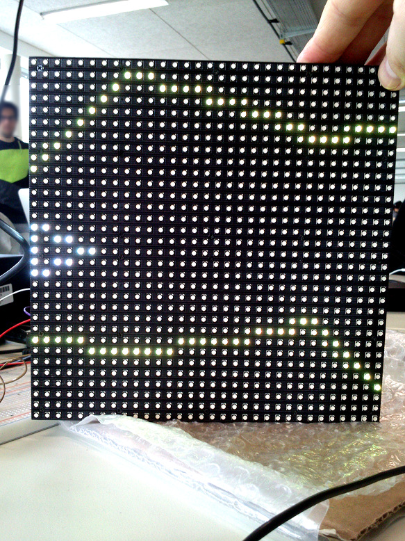
I learned something very important: I knew that, when working with ICs, it is mandatory that all their pins have a defined level. I was not aware of the fact that this is also mandatory when I am checking my electrical connections to learn whether I have powered board and LED matrix in the correct way.
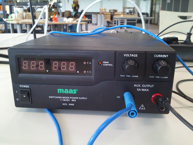
In my concrete situation this meant that I did not wire the data cables between matrix and Arduino but only the VCC and GND cables between the matrix and the power supply and those between the Arduino and the power supply. The result was that, when I turned on the power supply, that neither the Arduino nor the LED matrix seemed to draw power. When I disconnected the power cables to the LED matrix, the Arduino turned on. When I then reconnected the power cables to the LED matrix, the Arduino turned off. With a multimeter, I checked the power consumption of the LED matrix in this situation. It was nearly 5 Ampere. In practice it should consume at most 4 Ampere when all LEDs are turned on and maximum white. I was lucky that I had adjusted the current limit of the power supply to about 3 Ampere. Otherwise I might have destroyed both the Satshakit and the LED matrix.
The connection scheme between LED matrix and either an Arduino Uno or an Arduino Mega is detailed on Adafruit's well designed tutorial page .
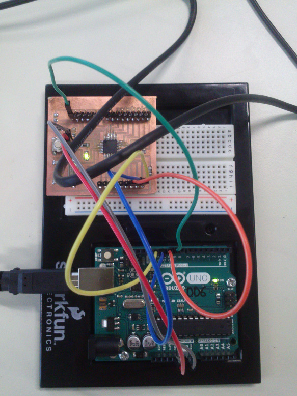
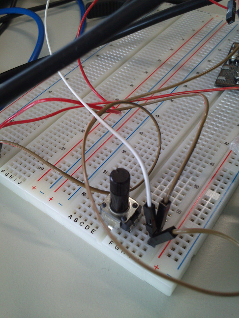
I added several other parts:
Desk power supply with 2.250 mA current and 5V voltage, GND and VCC attached via jumper wires to GND and VCC buses on the bread board
Potentiometer, with unknown parameters, middle pin attached to GND bus on the bread board, first outer pin connected to VCC bus on bread board, remaining pin connected to input pin A4 on the Satshakit,
FTDI cable, connected as detailed on Daniele Ingrassia's Satshakit page, but with the FTDI cable's GND connector connected with the GND bus on the bread board and the FTDI cable's VCC connector left unconnected.
It is important to link all GND potentials of your circuit to the ground cable of the power supply. The same holds true for the VCC potentials. In above description, I have referred to the points on the bread board where I have linked the potentials as "buses".
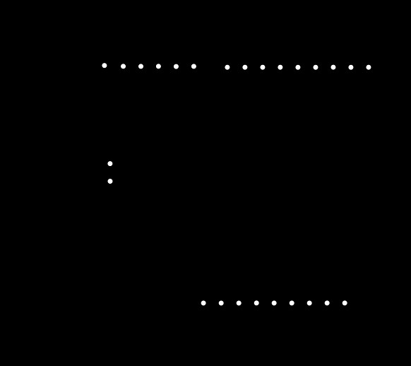
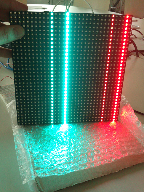
If you link the CLK, OE and LAT wires wrongly, you may be presented with a LED matrix that is powered but that may display the following:
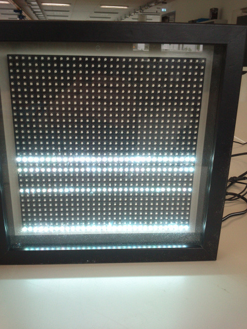
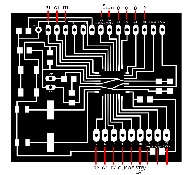
The connection scheme between LED matrix and Arduino Uno/Satshakit is as following (see also below images):
Upper RGB Data: R1 -> 2, G1 -> 3, B1 -> 4
Lower RGB Data: R2 -> 5, G2 -> 6, B2 -> 7
Row Select Lines: A -> A0, B -> A1, C -> A2, D - > A3
Latch wire: LAT/STB -> 10
CLK wire: CLK -> 8
Open Enable wire: OE -> 9
Grounds: GND -> GND
Space Wreck - a small demonstration
For testing, I have written a small horizontally scrolling game, Space Wreck, that lets you steer your space ship through a cave. You may change its vertical position through a potentiometer that is attached to the Satshakit.
The program keeps the y-positions of the ledges in arrays upperWall and lowerWall, six per screen width (32). For any eight scrolling steps to the left, the contents of the arrays are shifted to the left, and the "rightmost" array entry gets a new random value assigned. Variable cnt counts from 0 to 7 and is reset to 0 afterward. The polyline that the cave walls consist of is drawn at x-position 0 first when cnt = 0, then at -1 when cnt = 1 and finally at x-position -7 when cnt is 7. Only then the array entries are shifted to the left. The lines for the upper wall are drawn from (0, upperWall[0]) to (8, upperWall[1], then from (8, upperWall[1] to (16, upperWall[2]) and so on.
The game has no collision detection yet as I was low on memory on the Arduino. It shouldn't be hard to add collision detection. We need to know whether the ship's y-position at x-position 0 is on a wall pixel. To be precise, it is a little bit harder as the ship has a dimension. The y-position at x-position 0 of the walls could be computed from cnt, upperWall[0] and upperWall[1]. It helps that the x-position of the ship never changes. So far, as there is no collision detection, there is no space wreck...
I have added the necessary Adafruit libraries for the LED matrix and their abstracted graphics library for all of their devices, Adafruit-GFX-Library and RGB-matrix-Panel. However, in order to cram the code in the Arduino Uno's/Sathsakit's memory, I needed to get rid of some of the library functions in the Adafruit-GFX-Library. Please find the original libraries here.
//-------------------------------------------//
// SPACE WRECK
//
// by Thomas Laubach, 2016

// Include libraries for adafruit matrix
#include    // Core graphics library
#include  // Hardware-specific library

#define SHIP_COLOR matrix.Color333(7, 7, 7)
#define BG_COLOR matrix.Color333(0, 0, 0)

// Setup adafruit matrix
#define CLK 8
#define OE  9
#define LAT 10
#define A   A0
#define B   A1
#define C   A2
#define D   A3
RGBmatrixPanel matrix(A, B, C, D, CLK, LAT, OE, false);

static byte upperWall[6];
static byte lowerWall[6];
static byte cnt = 0;

unsigned static int gameTimer = 0;
unsigned static int ar; // Potentiometer value
static const int poti = A4;

static byte shipY;
static byte shipY_old = shipY;

boolean collision = false;

void setup()
{
  digitalWrite(poti, HIGH);

  // Initialize matrix and define text mode
  matrix.begin();
  matrix.setTextSize(1);
  matrix.setTextWrap(false);

}

// Main loop of the game
void loop()
{
  // Create the walls for the first screen (i.e, the first 32 positions)
  matrix.fillRect(0, 0, 31, 31, BG_COLOR);
  randomSeed(analogRead(2) + analogRead(5));
  for (byte i = 0; i < 6; i++)
  {
    upperWall[i] = random(0, 13);
    lowerWall[i] = 31 - random(0, 13);
  }
  drawShip();

  do
  {
    if (gameTimer % 20 == 0) { queryKnob(); }
    if (gameTimer % 100 == 0) { drawCaveWalls(); }
    if (gameTimer == 1000) { gameTimer = 0; } else { gameTimer++; }
  }
  while (!collision);

  // Collision occurred - blink ship
  for (byte i = 0; i < 8; i++)
  {
    matrix.fillRect(0, shipY_old, 6, 6, matrix.Color333(0, 0, 0));
    delay(150);
    matrix.drawLine(0, shipY+0, 0, shipY+4, SHIP_COLOR);
    matrix.drawLine(0, shipY+0, 5, shipY+2, SHIP_COLOR);
    matrix.drawLine(0, shipY+4, 5, shipY+2, SHIP_COLOR);
    delay(150);
  }
  collision = false;

} // loop

void queryKnob()
{
 ar = analogRead(poti);
 shipY = map(ar, 0, 1024, 1, 27);
 if (shipY != shipY_old)
 {
    drawShip();
    shipY_old = shipY;
 }
}

void drawShip()
{
   matrix.fillRect(0, shipY_old, 6, 6, matrix.Color333(0, 0, 0));

   matrix.drawLine(0, shipY+0, 0, shipY+4, SHIP_COLOR);
   matrix.drawLine(0, shipY+0, 5, shipY+2, SHIP_COLOR);
   matrix.drawLine(0, shipY+4, 5, shipY+2, SHIP_COLOR);
}


void drawCaveWalls()
{
  for (byte i = 0; i < 5; i++)
  {
    // Clear walls
    matrix.drawLine(i*8-cnt, upperWall[i], (i+1)*8-cnt, upperWall[i+1], BG_COLOR);
    matrix.drawLine(i*8-cnt, lowerWall[i], (i+1)*8-cnt, lowerWall[i+1], BG_COLOR);
  }

  if (cnt == 8)
  {
    cnt = 0;
    for (byte i = 0; i < 6; i++) { upperWall[i] = upperWall[i+1]; lowerWall[i] = lowerWall[i+1]; }

    upperWall[5] = random(0, 13);
    lowerWall[5] = 31 - random(0, 13);
  }
  else { cnt++; }

  // Draw walls
  for (byte i = 0; i < 6; i++)
  {
    matrix.drawLine(i*8-cnt, upperWall[i], (i+1)*8-cnt, upperWall[i+1], matrix.Color444(13, 13, 2));
    matrix.drawLine(i*8-cnt, lowerWall[i], (i+1)*8-cnt, lowerWall[i+1], matrix.Color444(13, 13, 2));
  }

  // Check collision between ship and the walls (simplified)
  // Please insert code for collision detection here (dependent on pos)
  // If collision occurred, set collision = true;
}
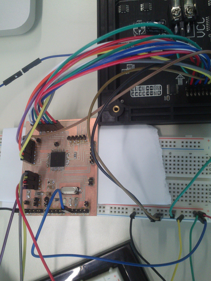
Combining my self-made VGS board and the LED matrix panel
I have designed a modified Satshakit 128 for my final project. As I have no fancy name for it so far, I simply call it the "VGS (Video Game System)" board for now. I connected this to the LED matrix panel. It can coexist smoothly with the LED matrix panel. While I was doing this, I learned another lesson: My design of the VGS board was based on the design of Daniele Ingrassia's Satshakit 128 which uses the "avr-developers.com boot loader". I burned this boot loader onto my VGS board and tested various sketches for the LED panel. They did not work, although I had checked the connections several times. In the end, I remembered to have used a different boot loader on the ATmega1284p, Jack Christensen's improved version of Maniacbug's "Mighty 1284p 16MHz using Optiboot" boot loader, for my Networking assignment. It can be found on Christensen's GITHub page. I burned this onto my VGS board instead of Daniele Ingrassia's. Now everything worked. The game shown in the video is my Breakout clone from my assignment on week 8.
Oftentimes, when I was connecting the LED matrix panel to one of the microcontroller boards I was using, the RGB LED matrix panel did not respond as intended. My experiences taught me that this was actually always my fault. Although the jumper wires look fragile, they were making surprisingly stable connections.
Source files
Design files for Daniele Ingrassia's new version of his Satshakit: hereBinary images that served as templates for milling with the FabModules: here
Small demonstrator (game "Space Wreck") with modified Adafruit libraries: here
Link to the files and the descriptions for my modified Satshakit 128 board: here
Lessons learned
- I must be even more careful when applying mechanical force to a bread board. I did not know how delicate the copper coat is.
- Milling boards is fun.
- It remains a challenge for me to solder SMD components, but I get better and better at it.
- I learned how to solder a microprocessor to a board. I also learned some important soldering techniques.
- While soldering, it is recommended to check the electrical connections/isolations of the component you have just soldered.
- When you test a circuit with ICs, link all cables to their respective inputs and outputs. Ensure that no pin at any IC has an undefined status.
- Thank you FabAcademy - I can now carry out things that I couldn't some months ago!
- When you are using a board design based on another person's design, you need to make sure that the boot loader for the alien board features the pin assignments that you need in your project.