Building the Board for my Video Game System
For this project, it was my plan to include all the work from the assignment on Networking: add a second microcontroller, let it communicate with the first microcontroller, add a SD card reader and read from it, then burn a game to the other microcontroller. Even though I did some extensive research on this in the last weeks, this was not crowned with success because of unforeseeable problems with the electronics. I was forced to streamline my project. I am now using a single self-made board with an ATmega1284p, the LED matrix panel, two embedded digital joysticks and two buttons and a small loudspeaker. I am confident to get the combination of two MCU boards working after some further research after FabAcademy.
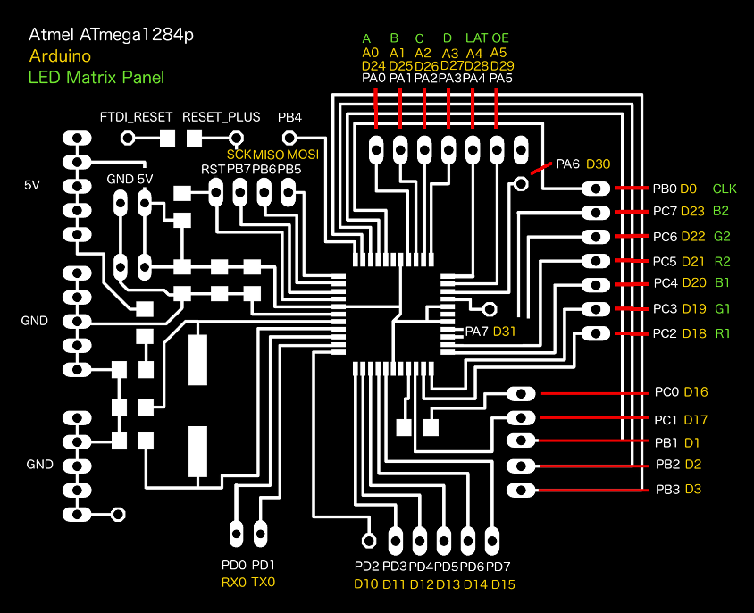
Pin usage of the ATmega1284p in my final project
I have thought about which pins of the ATmega1284p SMD I would use for which input and output devices. Had I been running out of pins, I would have added an I2C port expander, i. e., a 8574 (see this Arduino Learning section entry) to my design. For now it seems that I have enough pins at my disposal. I drew below chart and took a photo of it, as my scanner software was unable to connect to my computer. In GIMP, I brightened the scan, raised the contrast, did unsharp masking, then scaled the image to size.
The board design is an extension of the design Daniele Ingrassia did for his Satshakit 128. While the Satshakit 128 uses the "avr-developers.com pinouts 16MHz using Optiboot" bootloader, my board uses a modernized version of the "'maniacbug' Mighty 1284p 16MHz using Optiboot" bootloader by Jack Christensen. His updates can be found on his GITHub page. This is important, as the LED matrix panel requires the differing pinouts. My board and the LED matrix panel do not function together with the old bootloader version by Maniacbug.
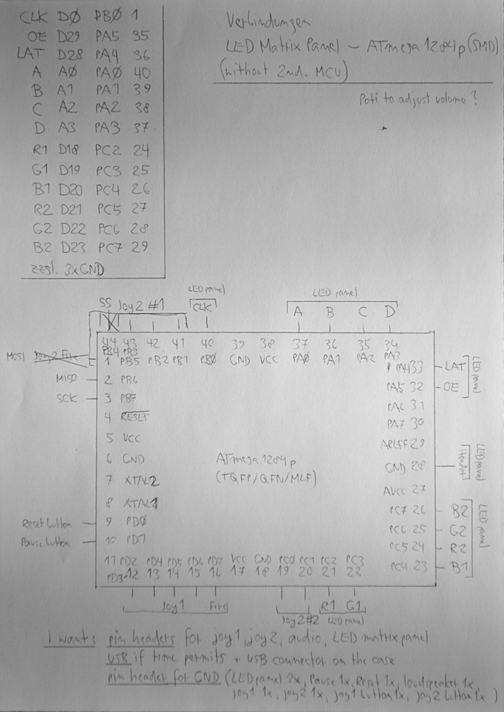
In order to get a working prototype ready, I decided to streamline my expectations for the final project. I will use only one MCU board and "load" new games not from SD card, but from the computer. The 32x32 LED matrix panel requires 13 pins, 10 digital and 4 analog, and 3 ground connections which are not absolutely necessary, as I have found out in my experiments. It is mandatory that the CLK pin is in PORTB. OE and LAT can go at arbitrary digital pins. The row select lines A-D need to go to analog pins. The data lines R1, ..., B2 cannot be placed somewhere else. If it can be done, I would like one header for all connections to the LED matrix panel.
Either of the two joysticks requires 4 digital pins for the switches plus 1 for the button.
The Reset button and the Pause button need 1 digital pin each.
For audio output to the small speaker, one additional digital pin is necessary.
I would like to have pin headers for the joysticks, the audio pin, the LED matrix panel and for GND, the latter with pins at least for 3x LED panel, 1x Pause button, 1x Reset button, 1x loudspeaker, 1x joystick1, 1x joystick2, 1x joystick button1, 1x joystick button2. I also need a pin header for the ISCP signals MISO, MOSI, SCK and SS.
Things that would be neat:
- A volume potentiometer between the speaker and the audio pin
- A barrel plug on the board for power
- A power jack on the case
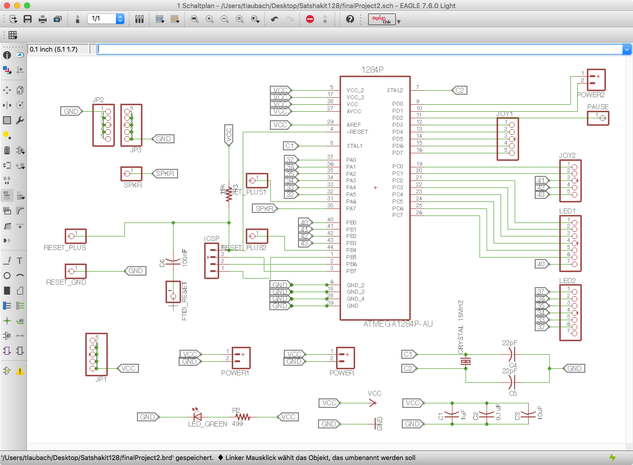
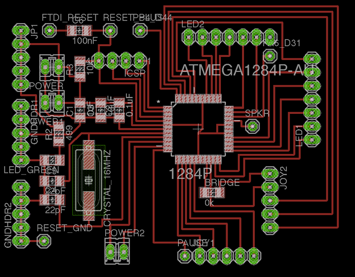
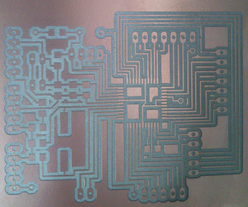
Designing and Milling the board for the Video Game System
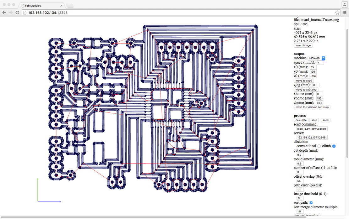
I designed the one-layer board for my Video Game System in EAGLE and milled the board on our Roland MDX-40 mill. For milling, I used the settings shown in the dialog windows in Fig. 3 and here:
        I am using an input image with 1500 dpi (cf. this file)

        Parameters used for milling

        Machine:                MDX-40
        Speed:                  4 mm/s
        x0 (mm):                35
        y0 (mm):                120
        z0 (mm):                -85.64

        direction:              climb
        cut depth (mm):         0.0
        tool diameter (mm):     0.2
        number of offsets:      8
        offset overlap (%):     55

        other parameters:       default

        The following applies only to our particular machine:
        send command:           mod_lp.py /dev/usb/lp0
        server:                 192.168.102.134:12345

        Parameters used for cutting

        Speed:                  0.3 mm/s
        x0 (mm):                35
        y0 (mm)                 120
        z0 (mm):                -83.6
        direction:              climb
        cut depth (mm):         1.9
        tool diameter (mm)      1.0
        number of offsets:      1
        offset overlap (%):     50

        other parameters:       default
I am producing eight offsets to my traces for simplified soldering. The EAGLE files can be found here, the binary images used for milling here.
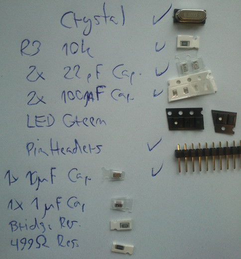
         Components used for the Video Game System Board

         1x ATmega1284P-AU

         1x Crystal     16MHz
         1x  10 kOhm    resistor
         1x   0 Ohm     resistor
         1x 499 Ohm     resistor
         2x  22 pF      capacitor
         2x 100 uF      capacitor
         1x  10 uF      capacitor
         1x   1 uF      capacitor

         Various pin headers
         1x Red LED

         For the bill of materials, exported from EAGLE 7.6.0, see the bill of materials
         which is reproduced below:

Partlist

Exported from finalProject_manual3.sch at 17.06.16 09:12

EAGLE Version 7.6.0 Copyright (c) 1988-2016 CadSoft

Assembly variant:

Part          Value          Device         Package                 Library       Sheet

1284P         ATMEGA1284P-AU ATMEGA1284P-AU QFP80P1200X1200X120-44N 1284          1
BRIDGE        0k             RES-US1206     R1206                   fab           1
C1            1uF            CAP-US1206     C1206                   fab           1
C2            0.1uF          CAP-US1206     C1206                   fab           1
C3            10uF           CAP-US1206     C1206                   fab           1
C4            22pF           CAP-US1206     C1206                   fab           1
C5            22pF           CAP-US1206     C1206                   fab           1
C6            100nF          CAP-US1206     C1206                   fab           1
CRYSTAL_16MHZ                CRYSTALHC49UP  HC49UP                  crystal       1
FTDI_RESET                   PINHD-1X1      1X01                    pinhead       1
GNDHDR1                      PINHD-1X5      1X05                    pinhead       1
GNDHDR2                      PINHD-1X5      1X05                    pinhead       1
ICSP                         MA04-1         MA04-1                  con-lstb      1
JOY1                         PINHD-1X5      1X05                    pinhead       1
JOY2                         PINHD-1X5      1X05                    pinhead       1
JP1                          PINHD-1X5      1X05                    pinhead       1
LED1                         PINHD-1X7      1X07                    pinhead       1
LED2                         PINHD-1X7      1X07                    pinhead       1
LED_GREEN                    LED1206        1206                    FAB_Hello     1
PA6_D31                      PINHD-1X1      1X01                    pinhead       1
PAUSE                        PINHD-1X1      1X01                    pinhead       1
PB4_D44                      PINHD-1X1      1X01                    pinhead       1
POWER                        M02            02P                     con-amp-quick 1
POWER1                       M02            02P                     con-amp-quick 1
POWER2                       M02            02P                     con-amp-quick 1
R2            499            RES-US1206     R1206                   fab           1
R3            10k            RES-US1206     R1206                   fab           1
RESET_GND                    PINHD-1X1      1X01                    pinhead       1
RESET_PLUS                   PINHD-1X1      1X01                    pinhead       1
SPKR                         PINHD-1X1      1X01                    pinhead       1
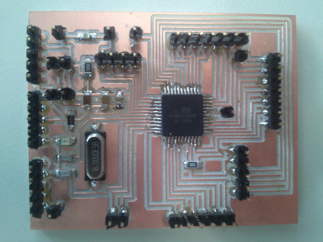
For programming, I linked my board and the Arduino Uno with jumper wires. I noticed that the jumper wires did not sit overly tight on the pin headers. The reason is that, while I was putting the pin headers at their positions, I pushed them too firm through the holes in the board. With the plastic sleeves on them, there simply is not enough space for the jumper wires to sit tight. Where this occured, I needed to remove the plastic sleeves.
Source files
Board Design, EAGLE files: EAGLE filesPNGs for Milling: PNGs for Milling
VGS board pin assignment diagram: VGS board pinouts
EAGLE 7.6.0 bill of materials: VGS board EAGLE 7.6.0 list of parts (bill of materials)
Lessons learned
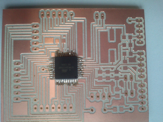
- I can now solder an Atmel ATmega1284p in SMD. This is incredible.
- To mill the board several times with a small offset makes soldering much easier.
- For a realistic project, it is very useful to add many GND and VCC pins to one's board design.
- Do not push the pin headers too deep into the board, because then the jumper wires will not sit tight enough on them