E09+10: Mechanical Design, Machine Design
This weeks assignments (week 09 + 10) are about Mechanical Design & Machine Making. This time it is a group task in which we have to build a machine that MAKEs something.
In our team at FabLab Kamp-Lintfort we did brainstorming and came up with some nice ideas. To foster a decision we classified them by dimensions of: craziness/ practicability and hardness/easiness.
The outcome of the process can be found here
At the end we decided to do a serious but not to serious machine that MAKEs fun to MAKE.
THE "PixelPlanter" ...!
![]()
Notes from lecture + comments:
Group Project and individual contribution
As mentioned, we developed the PixelPlanter as a group
All the documentation (even mine) can be found on our PixelPlanter group-page
Within this assignment, my tasks have been:
- Webpage for the group-assignment and landing page (FabLab Kamp-Lintfort) of the 2016' archive (adapted bootstrap template, created structure and content), see the results here
- Build FABNET USB (made PCB, soldering, programming)
- Set up Motor control/H-Bridge for the extruder (hardware and programming)
- Screw-extruder code & test (programming, physical testing)
- We did the assembly of the PixelPlanter all together, also testing, presentation, etc.
- I did the video below
Following are details about tasks I did on my own.
Electronics
While reading through the [m]MTM website we realized that we are missing a FABNET USB:
Fabnet is a multi-drop network, meaning that multiple modules (a.k.a. nodes) share a single set of communication wires. Signalling is differential based on the RS-485 specification. Each node is assigned a four-byte IP address which uniquely identifies it over the network. Besides communication, Fabnet provides power at two voltages: high voltage (12V - 24V) is intended to drive motors, lamps and actuators, while low voltage (7.5V) supplies power to the logic circuits of the nodes.http://mtm.cba.mit.edu/fabinabox/dev/fabnet/overview.html

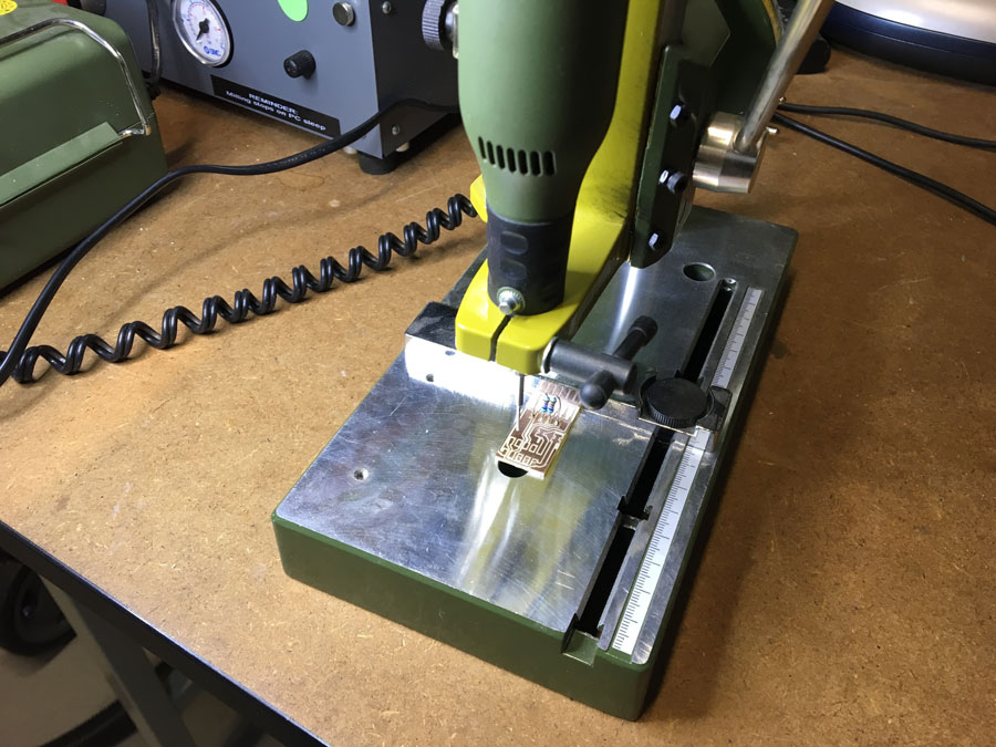
- We tried to produce the orignal FABNET USB board but for whatever reason there was a scaling issue. The Board appeared to be scaled up. Thus, we decided to use Bas's version of the board
- Here is a link to the MTM docu: Getting Started With Gestalt Nodes from the Tutorials Pages
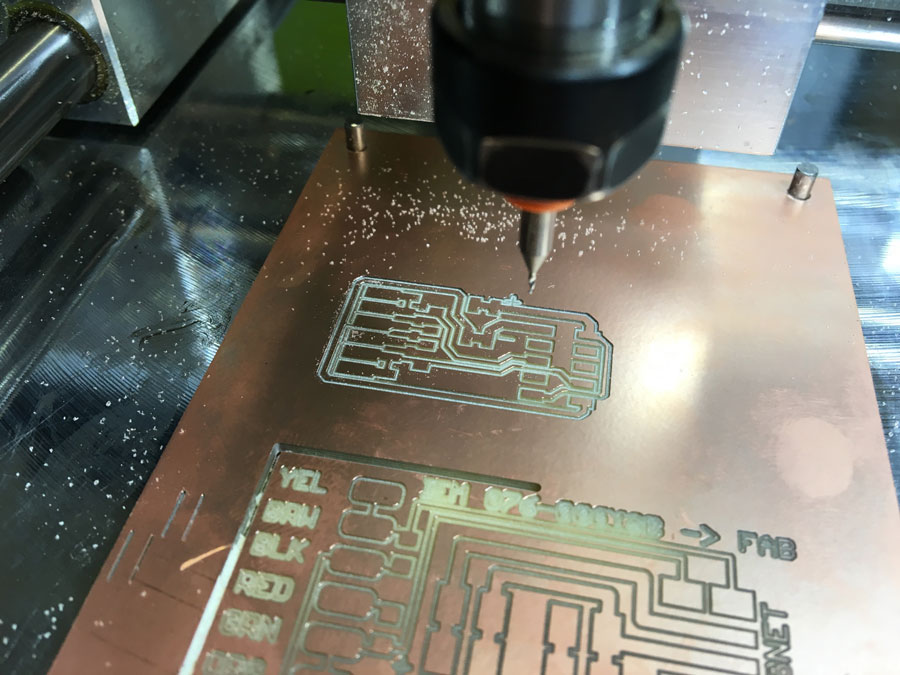
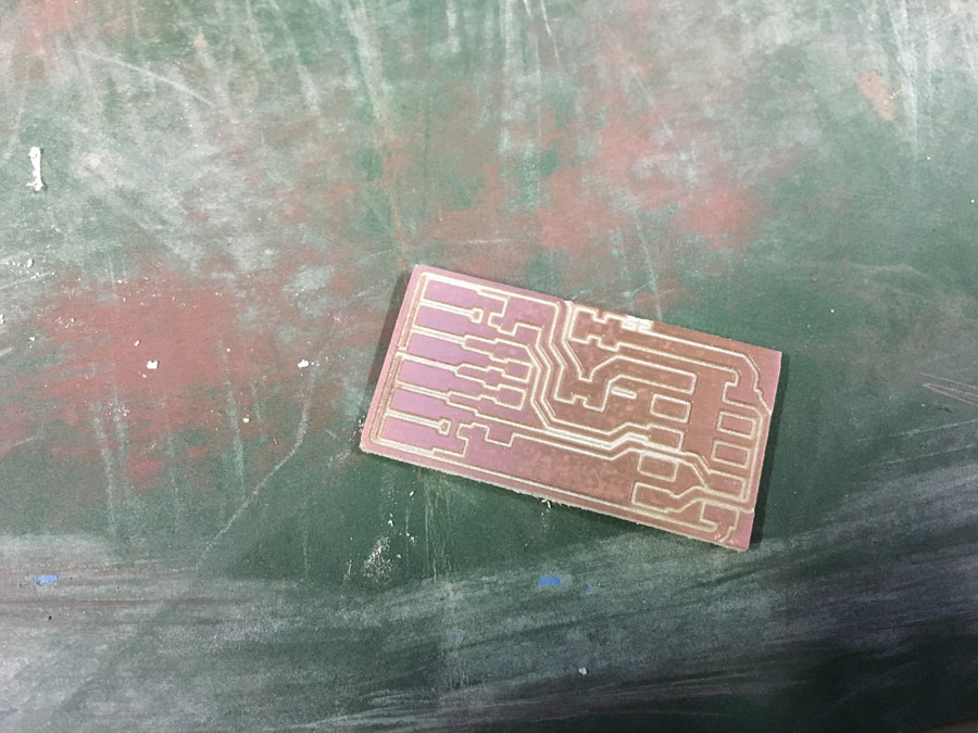
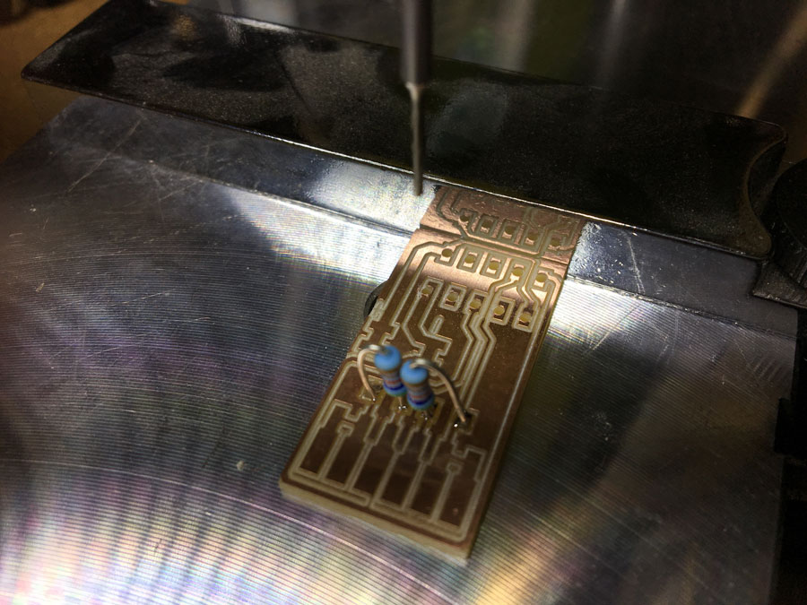
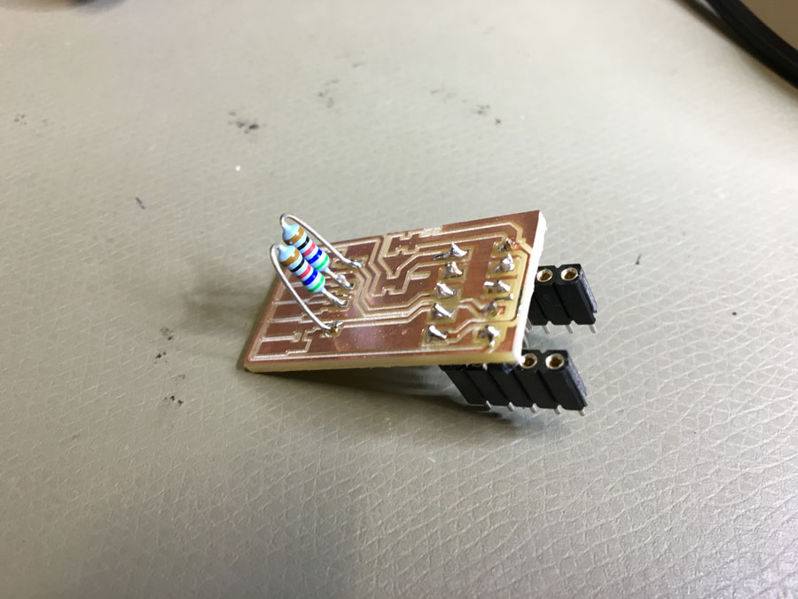
Milling the board, soldering the components, solder wires.
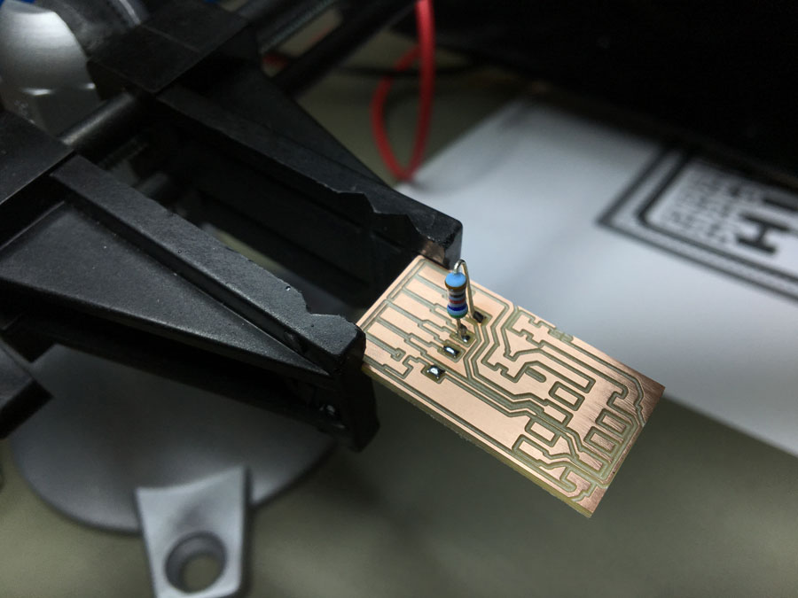
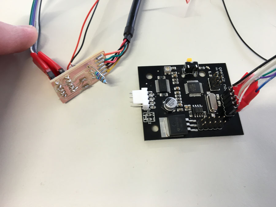
Finally, we connected the FABNET USB to the Gestalt-Node.
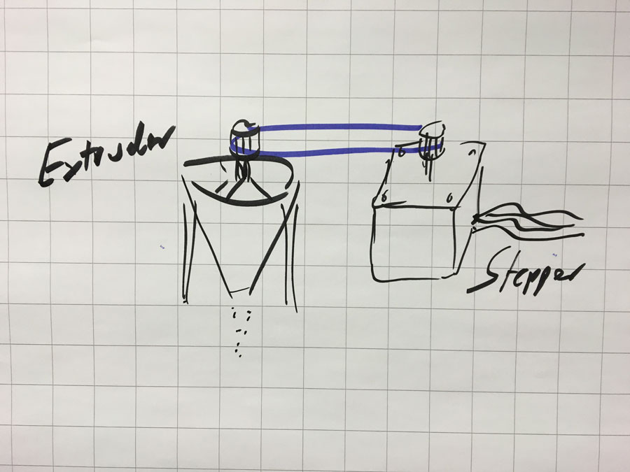
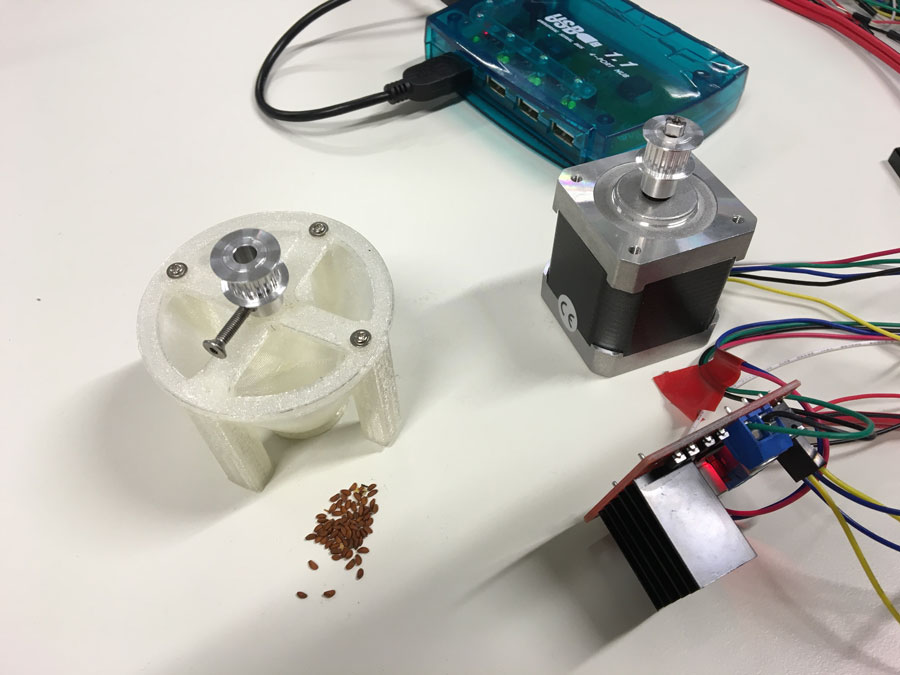
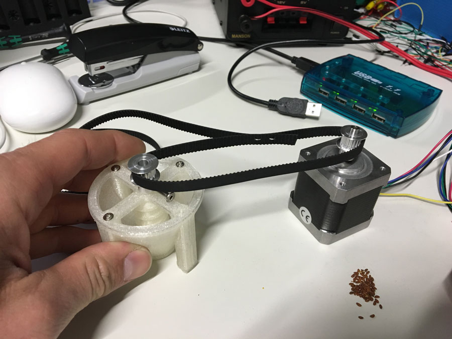
MAKE the screw-extruder turn
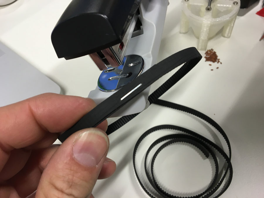
For the extrusion we thought about using a stepper motor (NEMA 17 Stepper motor) and a timing belt to make the screw-extruder turn.
I wanted to use the L298N Dual H-Bridge Motor Controller module with an Arduino. I found some tutorails about it, such as:
- Arduino Modules - L298N Dual H-Bridge Motor Controller
- Tutorial - L298N Dual Motor Controller Module 2A and Arduino
- How to drive a Stepper Motor using Arduino and L298H Bridge
Following picture and list shows the pin-layout of the L298N H-Bridge MC.
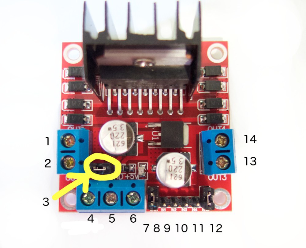
1. DC motor 1 “+” or stepper motor A+
2. DC motor 1 “-” or stepper motor A-
3. 12V jumper – remove this if using a supply voltage greater than 12V DC. This enables power to the onboard 5V regulator
4. Connect your motor supply voltage here, maximum of 35V DC. Remove 12V jumper if >12V DC
5. GND
6. 5V output if 12V jumper in place, ideal for powering your Arduino (etc)
7. DC motor 1 enable jumper. Leave this in place when using a stepper motor. Connect to PWM output for DC motor speed control.
8. IN1
9. IN2
10. IN3
11. IN4
12. DC motor 2 enable jumper. Leave this in place when using a stepper motor. Connect to PWM output for DC motor speed control.
13. DC motor 2 “+” or stepper motor B+
14. DC motor 2 “-” or stepper motor B-
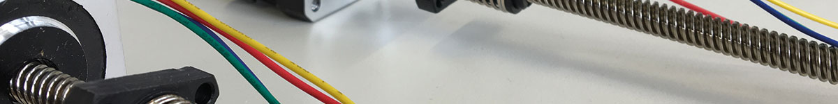
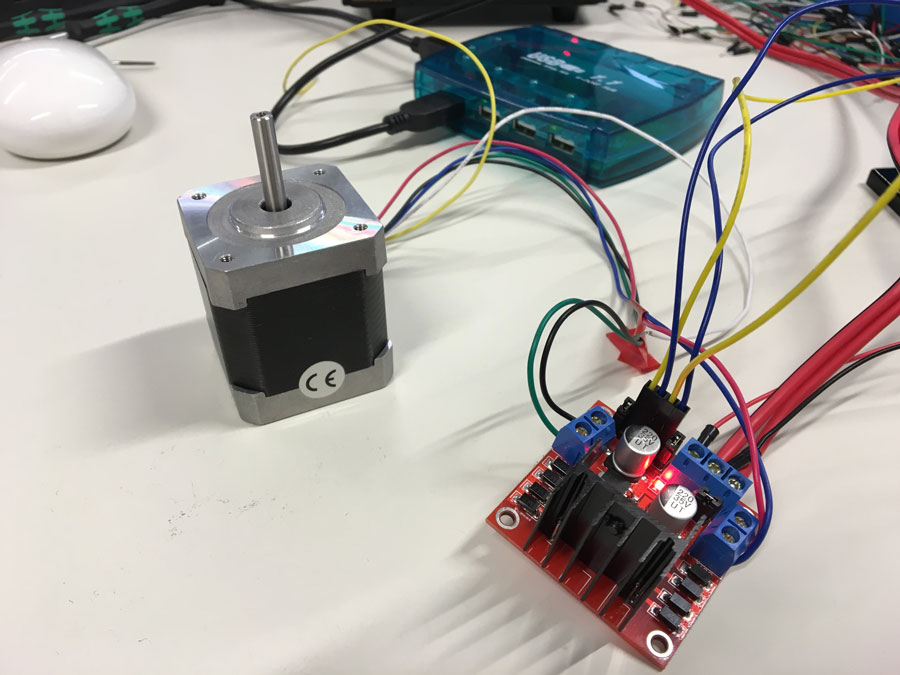
The NEMA 17 comes with 6 wires. Two of them are the pairs A+ & A- and B+ and B-. Here, it is black + green and red + blue. The white and yellow ones are not used.
Connect the motor in pairs to A+ & A- and B+ and B- connectors on the L298N module. Next, connect the power supply: positive to pin 4 on the module and negative/GND to pin 5. "If you supply is up to 12V you can leave in the 12V jumper (point 3 in the image above) and 5V will be available from pin 6 on the module. This can be fed to your Arduino’s 5V pin to power it from the motors’ power supply. Don’t forget to connect Arduino GND to pin 5 on the module as well to complete the circuit." http://tronixstuff.com/2014/11/25/tutorial-l298n-dual-motor-controller-modules-and-arduino/
You need 6 digital output pins on the Arduino, of which two of them need to be PWM pins (denoted by the tilde “~”).
The Arduino digital output pins D9, D8, D7 and D6 will be connected to pins IN1, IN2, IN3 and IN4.
"The motor direction is controlled by sending a HIGH or LOW signal to the drive for each motor (or channel). For example for motor one, a HIGH to IN1 and a LOW to IN2 will cause it to turn in one direction, and a LOW and HIGH will cause it to turn in the other direction.
However the motors will not turn until a HIGH is set to the enable pin (7 for motor one, 12 for motor two). And they can be turned off with a LOW to the same pin(s). However if you need to control the speed of the motors, the PWM signal from the digital pin connected to the enable pin can take care of it" http://tronixstuff.com/2014/11/25/tutorial-l298n-dual-motor-controller-modules-and-arduino/
Here, we just use one motor, but the principle is the same.
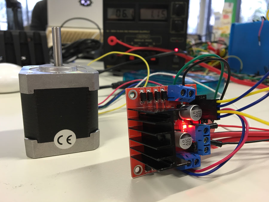
I supplied 12V to the Bridge and connected the arduino to my computer. To test it I simply used the demofile that comes with the Arduino examples: Files->Examples->Servo->Stepper Motor Control - one revolution
I wrote the code for the NAEMA Stepper motor. However, we run into some difficulties. The H-bridge (L298N DUAL FULL-BRIDGE DRIVER) ran hot.
Here is a description why: http://www.rugged-circuits.com/the-motor-driver-myth
As we want the motor to move forward and backwards continiously (for a short range of movements) so I put a delay between each movement. Because of that I thought of tunrning off the PWM pins fot that period of time. Thats why I made a simple For()-loop
for( int i=8; i<12; digitalWrite( i++, LOW ) ); in which I turned off all Pins. Well, it didn't helped.
So, I looked up the Datasheet and thought about using the two enable inputs: "Two enable inputs are provided to enable or disable the device independently of the input signals."
By doing this, I did a second trial.
/* Stepper Motor Control This program drives a unipolar or bipolar stepper motor. The motor is attached to digital pins 8 - 11 of the Arduino. The motor should revolve one revolution in one direction, then one revolution in the other direction. Modified 02.05.2016 by Karsten Nebe (based on code of by Tom Igoe) */ #includeint speed=120; int pause=500; // to prevet the H-Bridge from overheating, the motor enable pins will be manually turned off and on (when needed) int m1 = 12; // motor on/off pin int m2 = 13; // motor on/off pin const int stepsPerRevolution = 200; // change this to fit the number of steps per revolution // initialize the stepper library on pins 8 through 11: Stepper myStepper(stepsPerRevolution, 8, 9, 10, 11); void setup() { // set the speed at 60 rpm: myStepper.setSpeed(speed); // initialize the serial port: Serial.begin(9600); } void motorOn(){ // turn on motor enable pin 1 digitalWrite( m1, HIGH ); // turn on motor enable pin 2 digitalWrite( m2, HIGH ); } void motorOff(){ // turn on motor enable pin 1 digitalWrite( m1, HIGH ); // turn on motor enable pin 2 digitalWrite( m2, HIGH ); // turn off all input pins. for( int i=8; i<12; digitalWrite( i++, LOW ) ); } void loop() { // step one revolution in one direction: // Serial.println("clockwise"); motorOn(); myStepper.step(stepsPerRevolution); motorOff(); delay(pause); // step one revolution in the other direction: // Serial.println("counterclockwise"); motorOn(); myStepper.step(-stepsPerRevolution); motorOff(); delay(pause); }
Using the satshakit to run the motor of the extruder:
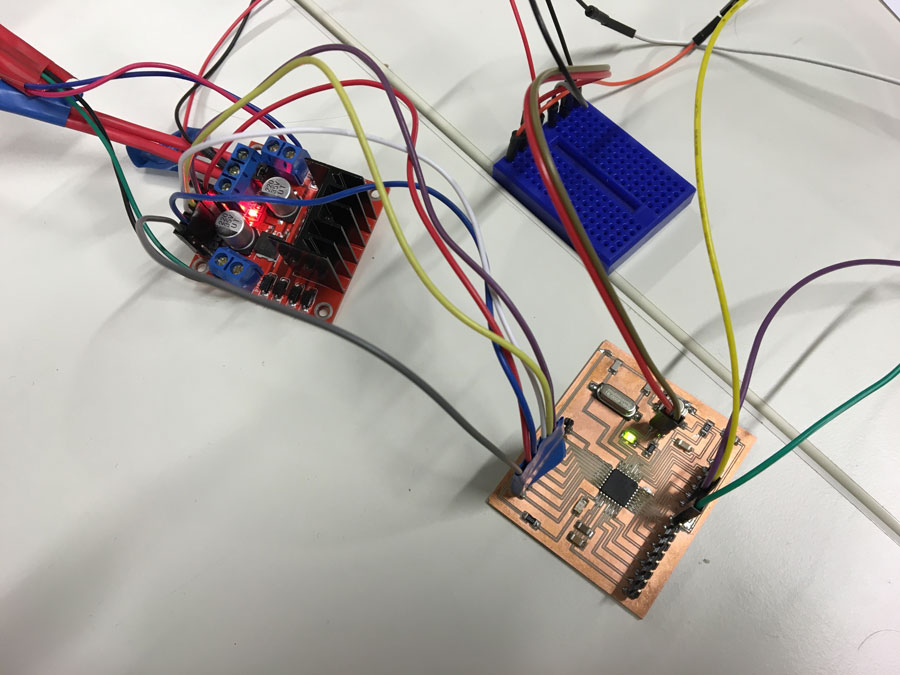
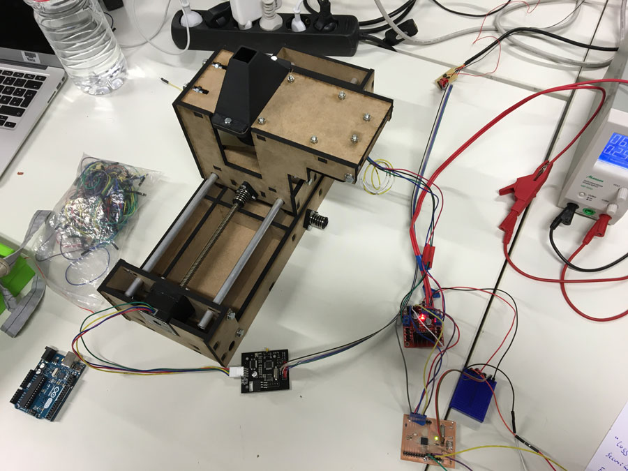
Finally, it works:
Take Away's