week 04 | 2016/02/24 - 2016/03/02 | 3D scanning and printing
11
Neil gave us the task to do a design rule check on all printers we have access to. In our lab we have access to some different models. Chri brought 2 more printer to test them also with us. Checking the design rules is a very important step before using a machine. Every 3d printers design rules were specified by it's mechanical structure, nozzle size, the extruder type (direct or bowden), the used filament, the CAM software and a lot of other influences.
The mechanical structure is the most important factor. Only if there is a reasonable, stiff mechanical construction, you are able to print complicate parts. For example, if one of your 3 axis is loose and sag, you're filament path won't fit exactly as calculated onto the last layer or your nozzle is too deep in the middle of your axis platform travel distance and scratches and burn your last layer.
The nozzle size is leading the quality of your print. The smaller the nozzle, the better the resolution of your print is(changing your CAM settings is obligatory). This gives you the ability to reach for example 30 layer for an 45 degree overhang instead of just 10 or so. But you buy this nice feature with the disadvantage with much longer print times. The extruder type is very significant for the factor, which material your printer is able to use.
A bowden extruder (like on an Ultimaker) is light, which gives you the ability for fast travel/printing but using flexible material is horrible. The bowden tube is even in PTFE not without any friction. So, you need a lot more power (which is not the problem) and friction on your filament to print. To reach the exact needed friction to print, you have to tweak a lot around - even within a spool filament, because their composition varies. Sometimes you have not enough friction and your extruder stepper is not able to push the filament through your hotend, or there is not enough friction and your extruder gear or bolt will grub into the filament. The direct extruder is normally direct above the hotend. This type feeds directly into the hotend without any curves, PTFE tube or something else. Instead of pushing the filament through a tube and increasing the force until it extrudes, the direct extruder is more - direct.
To see what I mean, go to the next Ultimaker, go into the maintenance menu, then advanced and use the option "move filament". After heating up the hotend, turn the knob slowly right until the first filament extrudes. You'll see that the PTFE tube will be strained a lot. There is mechanical movement in the tube and it's adapters. Before there is any extrusion, you'll have to reach peak, where your PTFE tube/bowden system is completely strained and the extrusion starts. While stopping the extrusion, you'll have to retract a much longer distance your filament to decrease the pressure in your hotend to prevent oozing. This costs time and precision in extruding material until there is no sensor or closed-loop control.
The filament quality is the next factor. We had so much different spools of filament, some were absolutely great, some were absolutely trash. Only while using good filament (even Ultimaker delivered a bad, glass-hard batch to us, which broke very often in the bowden tube, last year!) you and your printer are able to produce reproduceable results. Bad filament shows for example up with dust or any other impurity inside, the necessity to change your settings within the spool, breaking under small bending, no adhesion between the layer etc. The CAM software is a very interesting factor.
When I started printing, I used Skeinforge and Slic3r, but Skeinforge was definitely the better choice. There are much more options to manipulate the CAM algorithms than Slic3r ever had. For nearly every problem, there is a tab to fix it. After understanding this program, you are able to manipulate every given variable of your printer to print your file. It is equal whether you use plastic with a 0.4mm nozzle or ceramics with a 2mm nozzle. This software is absolutely freakin' - don't try to use it for the first time using a 3d printer. That is just frustrating! Skeinforge is even very slow (old python single thread code from 2012!) compared to Slic3r or Cura from Ultimaker. There is no 3d view, no chance to arrange different object or something else. Just the good old, flakey GUI. If somebody is interested in a Skeinforge workshop, just send me a mail.
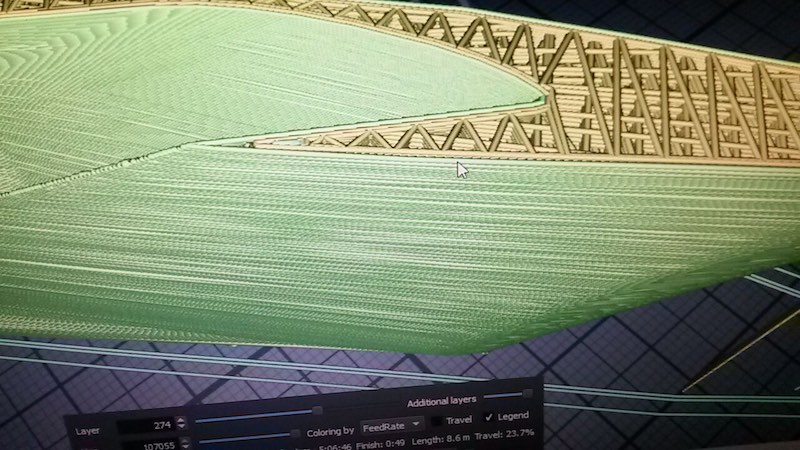
When it comes to shiny prints, use Cura or Slic3r - after years of slightly rough sides in our prints(we changed bearings, rods, whole printers to find these problems), we found out that Skeinforge includes a maybe floating-point error, which cause very slightly deformed sides. CraftWare includes a very good gcode viewer, which shows every fault in your code. Try it. :)
12
Skeinforge gcode in Craftware - as you can see, the walls are rough, which might be a floating point error in the algorithm.
13
14
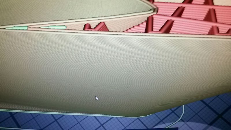
This is Cura gcode - absolutely fine surface.
15
16
Tested printers:
17
18
19
20
Orca v0.40 (after the last owner sold his company, there is no infomation or reference left)
21
22
23
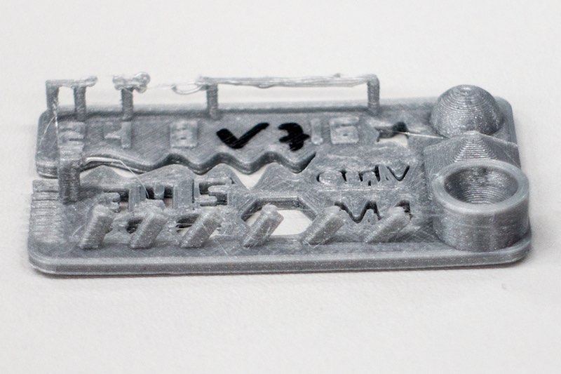
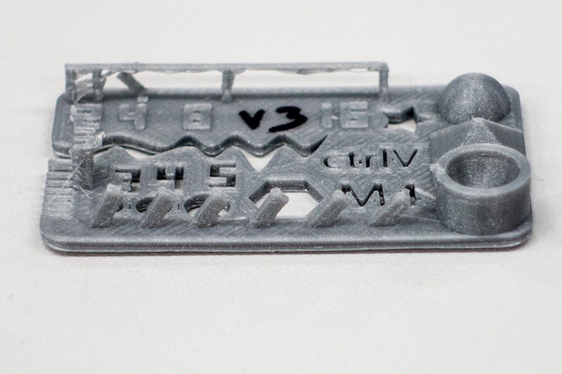
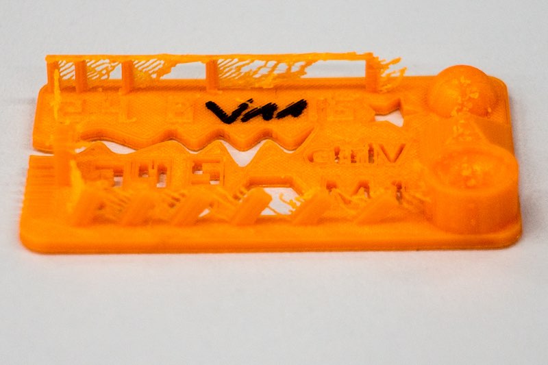
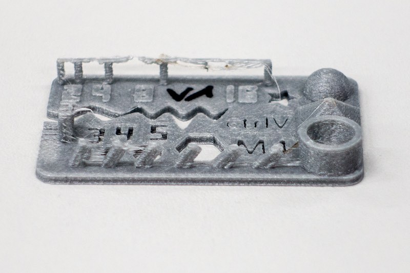
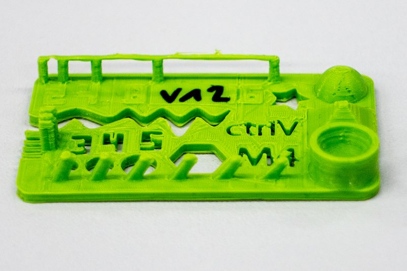
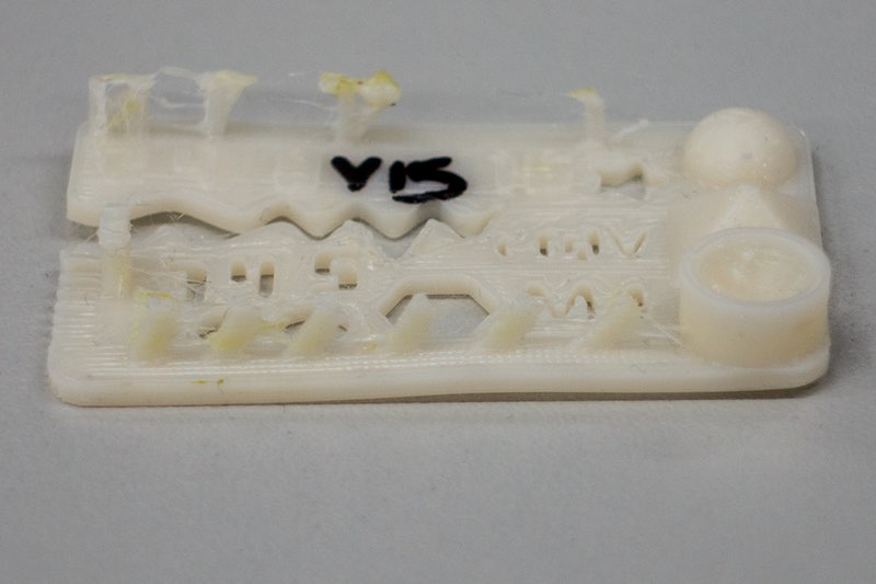
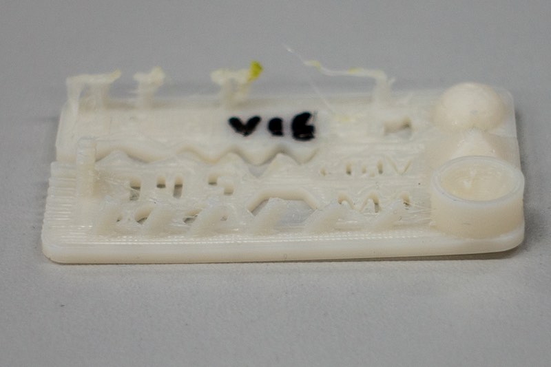
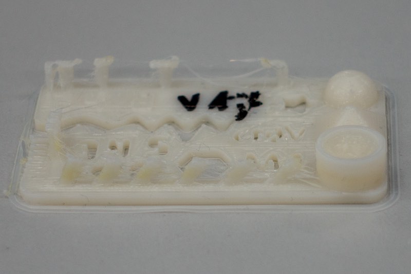
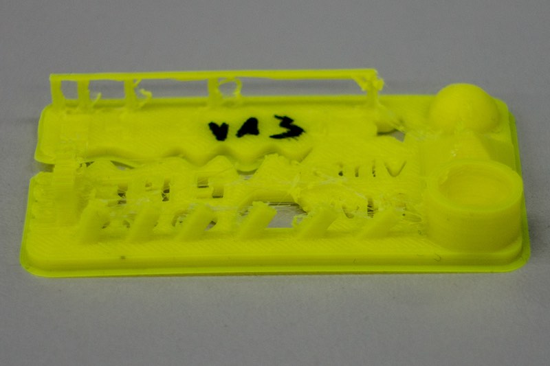
The next step was to decide how to do a design rule check on our printers. The last years, Chri and I had our own test part, which was simply called testc or later my derived version testd (the "d" is the actual revision). This is a very simple, fast to print, effective and material saving part. You can check the accuracy of your printer (line and holes), positive and negative 45 degree overhangs, extrusion rate/ratio, melting quality of your filament (deformed or burnt edges, flat or rough surface) and the way your CAM program works (is the circle closed? is there space between perimeter and infill?). This is not the right part to do a real design rule check, but we like to share this part with you! Feel free to use it. This is the first released version of our testd_v2! :)
24
Download my SolidWorks model file.
25
26
So, we searched, discussed and found a part, which includes all necessary test patterns to check the design rules. We decided to use the second generation of this test part, as we haven't seen a real advantage in the third version of this part.
27
28
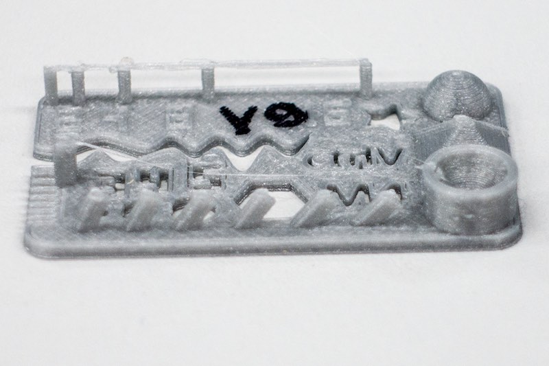
Ultimaker 2 Go, PLA, Cura, fast setting, cooling on, 20 minutes
29
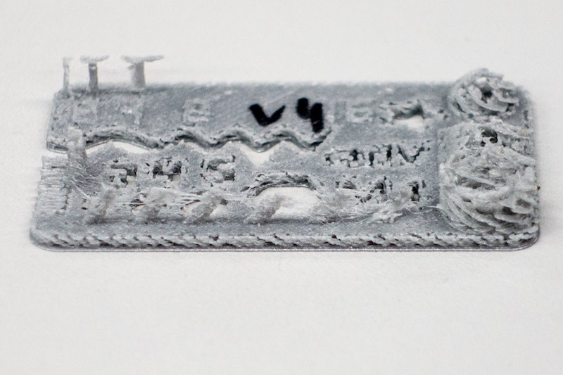
The resolution (even in x and y direction) is bad, there is a lot of space between perimeter and infill at the numbers. The long bridge is ok, the shorter not. This might be result out of the fast movement. The overhang is nearly perfect. The minimum distance walls on the left side failed. only 2 of 7 were printed! This setting is only useful for rough, fast prints.
30
31
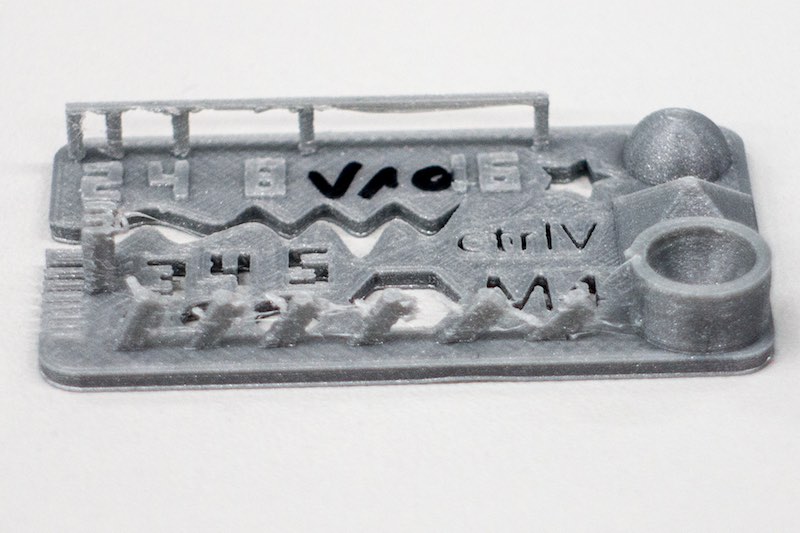
Ultimaker 2 Go, PLA, Cura, normal setting, cooling on, 51 minutes
32
This is one of our most interesting test prints. You'll see a lot of oozing - this is the only print where this printer had this failure. The resolution is a bit better, but not that good. I would not count this try.
33
34
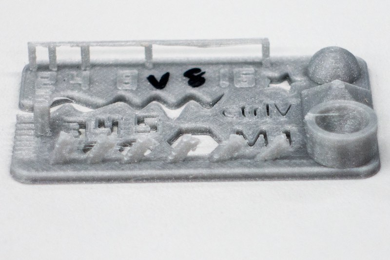
Ultimaker 2 Go, PLA, Cura, high setting, cooling on, 1h22
35
This result is much better than the result above. All bridges were printed correctly and really flat. The over all resolution is much better. This setting might be a good mixture of print time and quality.
36
37
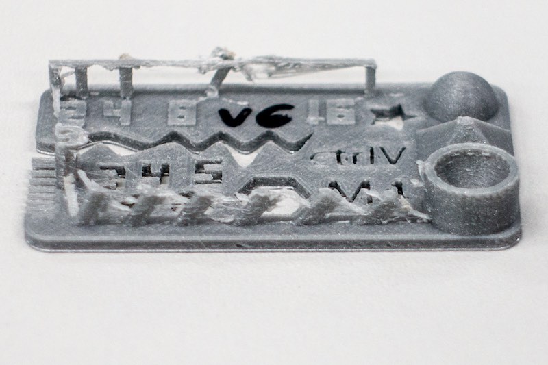
Ultimaker 2 Go, PLA, Cura, ulti setting, cooling on, 2h01
38
This setting is not worth the extra time, you only gain 0.02mm extra resolution. Yes, it looks a bit better than the high setting, but it costs a lot more time.
39
40
Ultimaker 2 Go conclusion
41
If you don't need a heated bed for Nylon, ABS or whatever, your parts don't exceed 120x120x115mm, use this machine. It is fairly fast but does not reach the 300mm/s under real conditions. Above 100mm/s the print with PLA is sloppy. Due to the fact that PLA has an other melting type than for example ABS or Nylon, we should try this also.
42
The Freakshow: Ultimaker 2 Go mod., PLA, 0.25 Nozzle, 1.75mm filament, high setting, cooling on, 50min
43
During our tests, I modified our second Ultimaker 2 Go from 2.85mm to 1.75mm and changed the normal hotend and nozzle to a olsson block. I had to change the filament diameter in the extended settings in Cura and in the printer itself. Without any correction at the flow setting or something else, I printed a testpart. It looks nice, all the edges are sharp due to the smaller nozzle. I should adjust and tweak the line width more and with more time, due to the fact that there are gaps between the perimeter and infill. This is on my to-do list. The 1.75mm version does not require that much force to print due to the smaller filament diameter. This might increase the bowden extruders reliability. It was just a small test beside our assignment. :)
44
45
46
Ultimaker 2, PLA, 230°C, Cura, fast setting, cooling on, 18 minutes
47
The normal Ultimaker with heated bed is not better in the fast setting than his smaller brother. The result looks like the 2 Go version of this print
48
49
Ultimaker 2, PLA, 230°C, Cura, normal setting, cooling on, 48 minutes
50
In this setting, the normal Ultimaker 2 printed a lot better, there is not that much oozing, the bridge is nearly perfect and stable. There is only little oozing in the overhang section. This is a good setting for functional prints. With the 0.1mm layer height, there is enough resolution for small or high detail models.
51
52
Ultimaker 2, PLA, 230°C, Cura, high setting, cooling on, 1h19
53
This is interesting print. The normal print looked way better than this high setting print. The print has a more rough surface. I would not count this failed print. There are many options which can cause this behaviour.
54
55
Ultimaker 2, PLA, 230°C, Cura, ulti setting, cooling on, 1h58
56
This print failed completely. The bridge is not correctly printed. A lot of oozing. The surface is rough like at the high settings. As I said above, we got a bad batch of filament, this could be such a spot in this spool.
57
58
Ultimaker 2 extended, PLA, 230°C, Cura, normal setting, cooling on, 51 minutes
59
There is even a very rough surface. When you compare this to the 2 Go print (which was supplied with a newer batch of filament!), you don't believe that the only real difference between those 2 printers is a nearly 10cm longer bowden tube. We had a lot of spools which printed sometimes perfectly and sometime the clogged the hotend every 5 minutes.
60
61
Ultimaker 2 extended, PLA, 230°C, Cura, high setting, cooling on, 1h22
62
Eh... this spool is trash.
63
64
Orca XXL, ABS, 250°C, Slic3r, 0.1mm layer, 0.4mm nozzle, no cooling, ~30 minutes
65
This result is nice. We used Slic3r as CAM software, which generated a gcode with 6 out of 7 of the minimum distance walls. There is only little oozing. The bridge is nice and flat. None of the overhangs was a problem for this printer. For a printer without cooling, this result is impressive.
66
67
Orca v0.40, PLA, 230°C, Skeinforge, 0.1mm layer, 0.4mm nozzle, no cooling, ~45 minutes
68
As you can see, both Orca printer were not made for PLA and shiny printing. They are tools to produce mechanical stuff out of Nylon, ABS or flexible material. This print is even very nice. It is made out of PLA, the bridges are fine, the surface is nearly flat and really closed. The PLA we used in this printer looks like a better quality than the Ultimaker original one. There is no oozing. The perimeter are completely connected to the infill. There is absolutely no gap. This function lags really in Cura! Looks nice, smells nice. :)
69
70
Orca v0.40, Arnitel 45 Shore D, 250°C, Skeinforge, 0.1mm layer, 0.4mm nozzle, no cooling, ~45 minutes
71
Due to the fact that both Orcas use a direct drive extruder, we were able to print flexible material also. In 1.75mm we had Arnitel material, which was supplied by the Orca manufacturer some years ago. This is a very nice material. It contains out of 50% rapeseed oil instead of mineral oil. The Material is due to its softness hard to print. The bridges failed completely at 40mm/s and even slower. The other test sections are nice. Even the resolution for a 0.4mm nozzle with flexible material is ok. We did 3 test parts with this material. They vary in speed from 40mm/s to 20mm/s. In the last print, you can see some beginning from the bridges. Printing even slower could end in better results.
72
73
74
75
Beiwagerl, ABS, 250°C, Slic3r, 0.1mm layer, 0.4mm nozzle, no cooling, ~30 minutes
76
This is our Beiwagerl, Chri and I designed it in fall 2012. It is small, has 100x100x100 print volume, a heated printbed and is able to print even ABS or Nylon. It is made for high-speed printing. Watch this video. We printed a test part on it. The spool was very old (one of the first shippings from china - must be 2013 or so), but it printed - ok, there was a bit oozing - nice. The surface is closed, the bridge is solid and the overhang is ok. This print was done with 50mm/s.
77
78
Conclusion
79
All our printers have positive and negative aspects. The design rules to user our printer are relatively easy. The minimum wall thickness must be over 0.4mm. Bridges up to 16mm are not a problem, overhangs up to 45 degree are even absolutely no problem. Above this, use support material (normally Skeinforge and Slic3r are set to use support material above 60 degree). The Ultimaker (all of them) printing 0.3mm to large, the Orcas 0.05mm to small (ok, they are nearly calibrated by us), the Beiwagerl is even 0.3mm to large in its printing dimensions.

This work by Daniel Bruns is licensed under a Creative Commons Attribution-NonCommercial-ShareAlike 4.0 International License.