final project -- weekly assignments -- about me -- fab academy
Week 12: That Gearbox Doesn't Sound Well...
Output Devices... As LEDs are boring and I need to drive DC motors for my final project, I decided to implement the first step of DC motor control: Setting the motor voltage. A common way to do that is by using PWM - Pulse Width Modulation, switching the voltage on and off quick enough so the user (hopefully) will not notice. In Theory, you can get near-DC results with the right filtering... In Practice, that is rarely done and often not sensible.
I do have a board with a dsPIC on it and a 6A full bridge, I built two of them before to put them into standard RC servos, and I want to use their basic schematic for my final project. The one I used is already stuffed into one of the cheapest servos I could find:
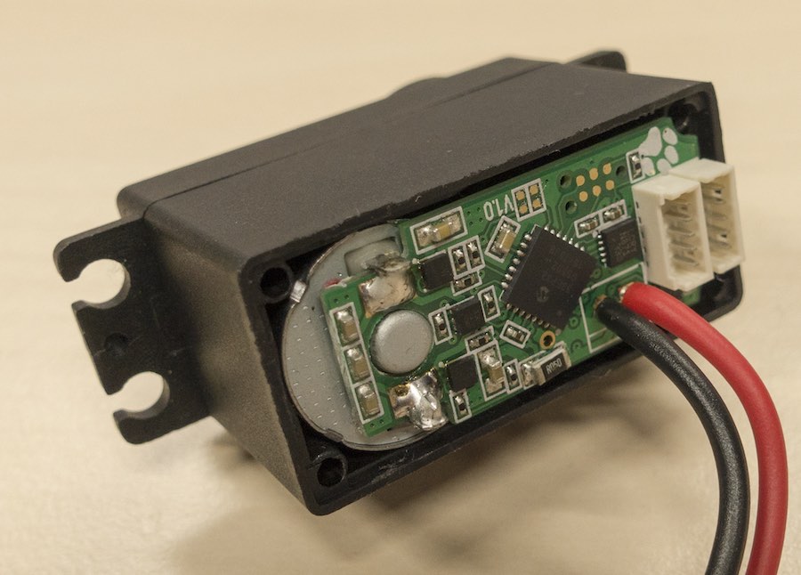
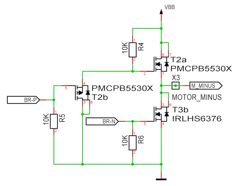
Those three little squares near the motor form the H-Bridge - Each of those is a pack of two MOSFETs, adding up to two half bridges like this one:
TODO: PDF of the schematic, project files
dsPIC PWM Basics
Contrary to their 8 Bit counterparts, the 16 Bit PICs have PWM modules that are so packed with features you have to read a serious amount of documentation to get at them (30 pages of register descriptions...?!?). Luckily, to simply drive a DC motor I will not need most of them, and can leave a lot of configuration stuff alone.
As a first basic principle, all PWM modules are synchronized by a master time base unless you explicitly configure them not to be. That has its advantages driving multi-phase inverters, but makes all those shiny overview schematics a holy mess. I just used a more or less standard configuration from the datasheet here, with an auxiliary clock derived from the internal RC oscillator, running at roughly 118MHz. That sounds like a lot, but actually isn't - To get 16 bits of resolution, the PWM has to count up 65536 steps, breaking that fast clock down to a mere 2kHz. Most humans can hear 2kHz really fine, which is why that fast clock is multiplied by 8 internally.
For this week, I intentionally slowed down the PWM module for a bunch of reasons. First, Transistors don't switch instantly. While switching, they burn power and heat up, which is why high switching frequencies can result in a lot of heat, which is not something I want to have on a completely untested board. Second, a low PWM frequency gives me the advantage of actually hearing what happens, so if strange stuff happens I might instantly know more. Third, classic DC motors tend to get stuck at low resulting voltages and high PWM frequencies, so that's another source of errors I don't want to have now.
A nice feature of the PWM module is automatic dead-time generation. Again, Transistors don't switch instantly, so you have to wait for one to actually turn off before turning on the other one. That waiting time can be configured and will be added automatically... For this week, I set it to an insanely long time just to be safe.
PWM resolution (and Frequency) also result from the amount of timer ticks you count. I reduced the resolution to 15 bits, more from a hunch than anything else. It allows me to store the voltage level as well as the polarity in a single integer, which is nice.
What You Don't See...
... makes you scream. There is one feature that is, contrary to everything else, enabled after a reset. A feature I don't need, don't want and didn't even think about: The inputs for an external overcurrent protection circuit. Thanks, microchip, it only took me two interesting hours of swearing debugging to find that one.
Results
With a bit of playing around and some really ugly delays...:
It really sounds awesome awful. Cheap stuff, those gears...
As always, the sources are ready for downloading.
final project -- weekly assignments -- about me -- fab academy
