final project -- weekly assignments -- about me -- fab academy
Week 10: Input Devices
As I have come to expect, this week was chaos. So, while I had started out doing the first hands-on work for my final project, none of its "input"-PCBs could be ready on time to do this week's assignment on it. I don't want to do a simple button (buttons are just boring until they bounce...), so I felt compelled to do something else.
Hardware
Daniel will need a bunch of distance sensors for his final project. The ones he will be using do look nice as they are small (compared to bulky ultrasonic sensors) and should be fairly directional - they are "looking" at a dot of light, not a diffuse reflection of a target somewhere roughly in front of them. So, I borrowed one to have a look myself.
I had made a bunch of USB test boards for I2C-Sensors a while ago, mainly to play around with stuff like the Invensense IMUs or the barometric sensors I stumbled upon.
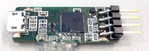
I had made them as a variant of another board, so they are rather limited in what they can do (two available pins are just barely enough to do anything), but for reading out a single I2C sensor they should just work. They are built around a Texas Instruments MSP430, a low-power microcontroller family I have done some work with for the lab. And while their documentation is horrible in some areas, the USB stack is well documented and just works. If you want to make your own, the design files (done in Target 3001!) are here.
For the proximity sensor, I fired up Kicad and made a tiny board to plug into the USB-thing:
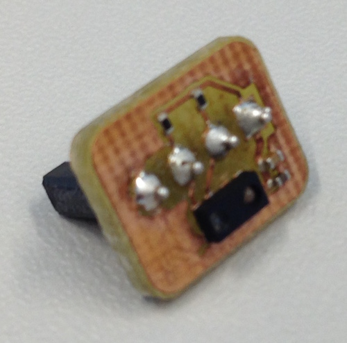
Again, it doesn't do much - it's just the bare minimum connection the VCNL4040 datasheet implies, not even connecting the interrupt pin (which I don't need, anyway). Not thinking straight, I also added the I2C pullup resistors to the board - there already is a pair on the USB board. It should work with them, though, and if not, I can still remove them. Again, if you want to build your own, do so: Sensor-Subboard Kicad Project
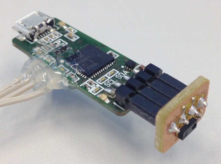
(The hot glue-stuff is the debug interface, by the way...)
Software
To play around with the sensor, I basically need three things:
- Software to do I2C
- Software to actually talk to the sensor (on top of the I2C stuff)
- Some kind of way to get at the sensor data I have read
General Software Stuff
The last part can, for the time being, be replaced by using the debugger and just reading from the microcontroller's memory. While not particularly convenient, this works fine for a first test. In the long run, I want to use USB for that, of course, so I will start out with one of TI's sample projects for USB - a virtual COM port that echos back any data you throw at it. That way, it will be easy to add in the USB output later, and until then it conveniently provides me with almost-done initialization routines for stuff like the somewhat complex clock system. I will, of course, have to change the I/O-initializations - I put in a way to switch off power to the sensor, which I now have to switch on, and I will have to configure the I2C pins to do their job. There are two LEDs, too, that I want to use at some point to show what the board is doing.
So, I need the following Changes to the default peripheral configuration:
- Configure P4.3 as a special function pin (SDA)
- Map SDA to use P4.3
- Configure P4.4 as a special function pin (SCL)
- Map SCL to use P4.4
- Configure PJ.2 as an output and set it to high (3.3V-Switch)
- Configure P1.0 as an output and set it to high (LED2, USB-side of the board)
- Configure P4.7 as an output and set it to high (LED1, I2C-side of the board)
To achieve those, I added some code to the imported TI initialization (in USBHAL_initPorts(void), hal.c):
// Configure port mapping controller
// interrupts have to be off at this point!
PMAPKEYID = 0x2D52; // unlock port mapping controller
PMAPCTL |= PMAPRECFG; // allow multiple unlocks
P4MAP1 = PM_NONE; // discard mapping of SDA to P4.1
P4MAP2 = PM_NONE; // discard mapping of SCL to P4.2
P4MAP3 = PM_UCB1SDA; // P4.3 -> USCI B SDA
P4MAP4 = PM_UCB1SCL; // P4.4 -> USCI B SCL
// for safety reasons we relock the port mapping controller:
PMAPKEYID = 0xFFFF; // wrong value locks the controller
// Reconfigure I/O-pins as needed
// The TI init already sets everything to output and low,
// so we don't have to set that
P4SEL |= BIT3 | BIT4; // set P4.3 and P4.4 to special function
P4OUT |= BIT7; // Turn LED1 off
P1OUT |= BIT0; // Turn LED2 off
General setup stuff is more or less done with that.
I2C-Software
As I want to reuse the sensor reading code
Sensor Reading Software
The sensor looks like a rather simple device, from a software point of view: It has 13 registers, each of them 16 bits long (and thus, for I2C, split into two bytes each). Into eight of them, you can write configuration to tell the sensor how to do its job. From others, you can read results. So, with I2C working, talking to the sensor shouldn't be hard - a few write tasks to configure it (if needed), and then a few read tasks to get results. The datasheet comes with a nice map of the registers:
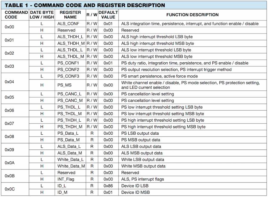
Given that I won't be using the interrupt feature for now, I can immediately discard Registers 1, 2, 6 and 7, leaving me with a maximum of four configuration registers to potentially write, with a lot of the short descriptions pointing at fairly obvious stuff - Switching the interrupt function on and off, setting the output resolution...
The first "command code" to look at is 0x00, doing configuration of the ambient light sensor. Since I don't want to use it, I can set the register to 0, disabling the ambient light sensor.
The second is 0x03, leading to registers PS_CONF1 and PS_CONF2.
I'm off to work for now as my spare time is up, so I'll have to continue fiddling with the firmware and writing stuff up later.
final project -- weekly assignments -- about me -- fab academy
