Rhino and Grasshopper
I've never used any of these programs, so once again starting from scratch, I've decided to focus on Grasshopper for the moment.
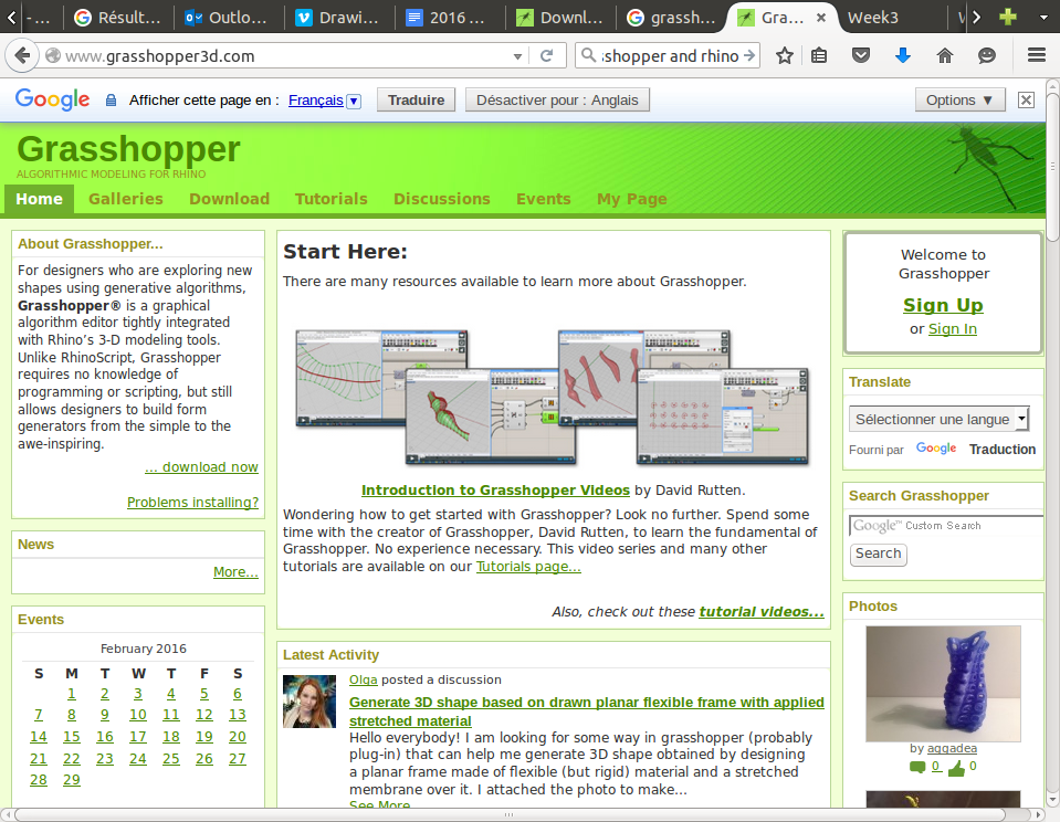
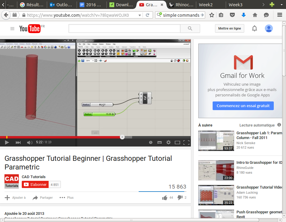
I first watched tutorials on youtube to see how the interface looked like and to be sure I would feel comfortable with it: (first video on youtube)
Next I had to download Rhino:
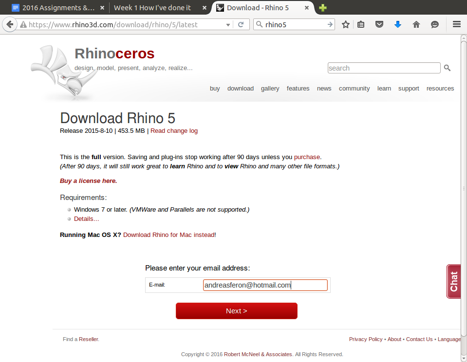
They just ask you to put your e-mail adress and you'll get a full version for 90 days.
Here is the link :Rhino 5 (90 days )
Then it is time to install Grasshopper which is a plugin for Rhino 5:
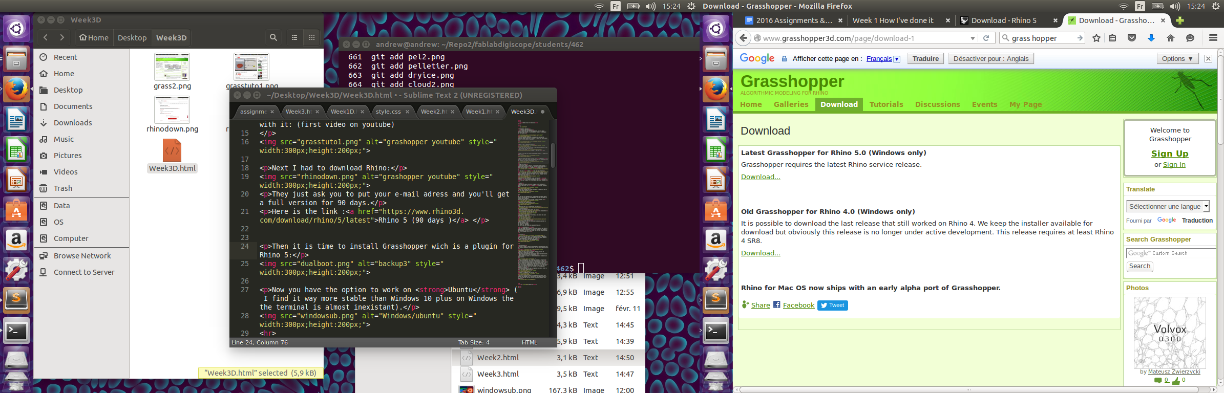
Once again they ask for you e-mail adreess.
Ok, so now you've got every thing you need to start learning parametric design!
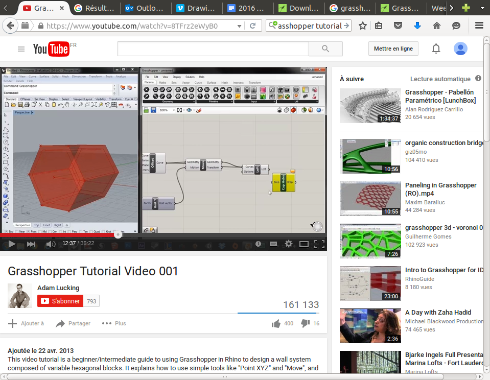
Lets follow our first turorial, I've got two screens so on one there is the video :
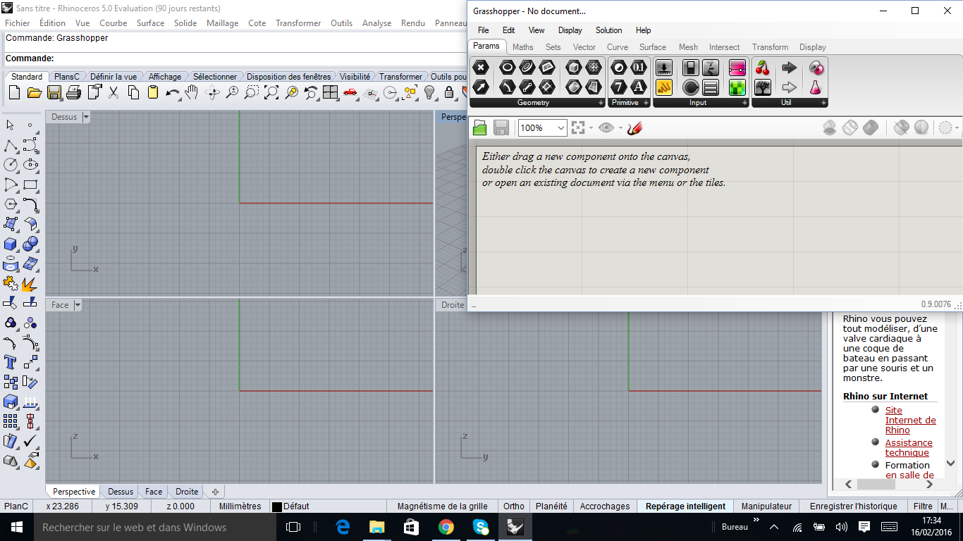
And on the other screen I've got my program:
So after playing around I decided I would try something harder, I wanted to make a parametric design that could allow me to create the perfect heat sink for my project
Using my knowledge in thermodynamics to try to have a surface that could optimise the heat transfer.
I've watch several tutorials to find all the bits that I needed, and then I started:
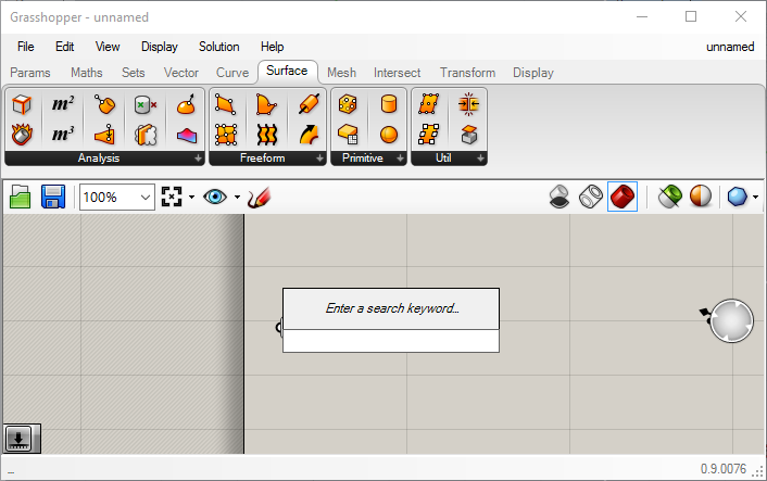
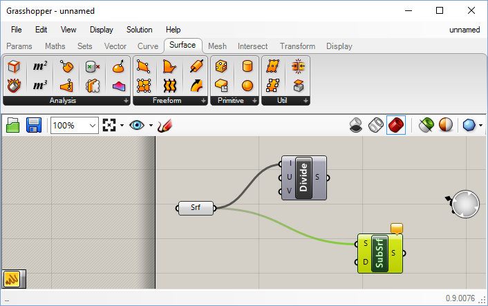
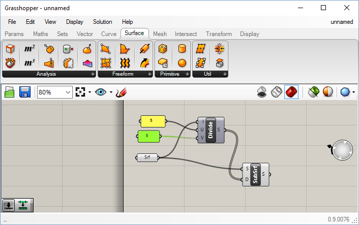
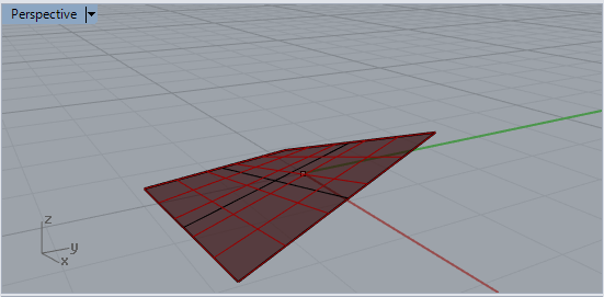
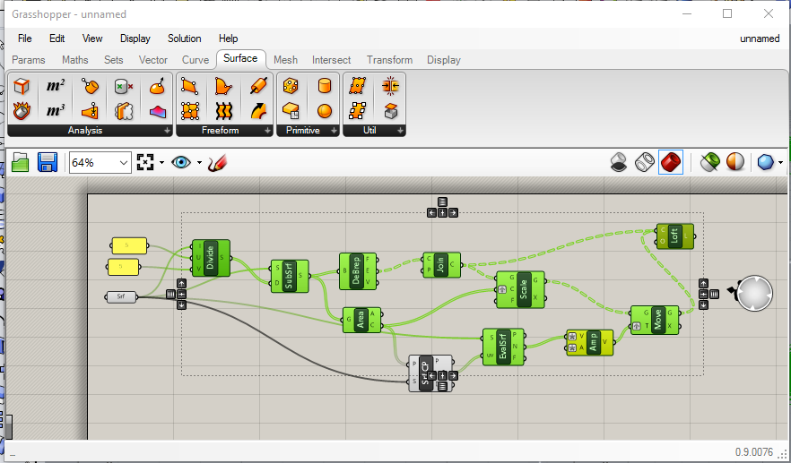
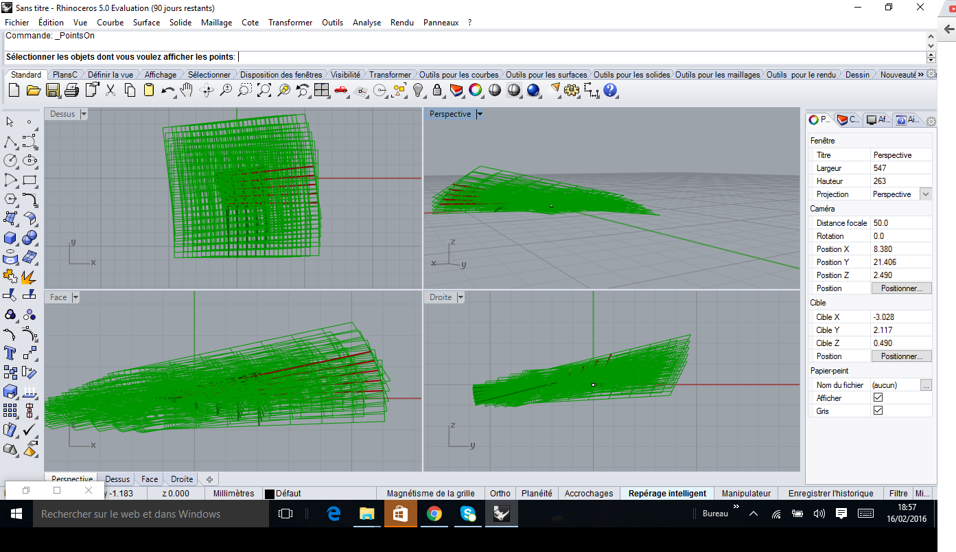
I've managed to mesh my surface and create normal vectors to each sub-surface I created, but when I tried to join the projection of my inner surface the "LOFT" option is also taking my outside vectors in account,so I need to find a way of deleting those outer vectors and just keep the normal ones.
My dxf file : first test
I already spent quite some time on this, so for the moment I am going to leave it there and try something else.
There are plenty of other programs to discover!
SolidWorks
SolidWorks is a powerfull tool that allows you to design 3D objetcs starting with a 2D sketchs.
It also allows you to build assemblies and simulations (thermal,mechanical...)
For a training I've decided to make several mechanical pieces with different levels of difficulty, I had already some experience but only the basics.
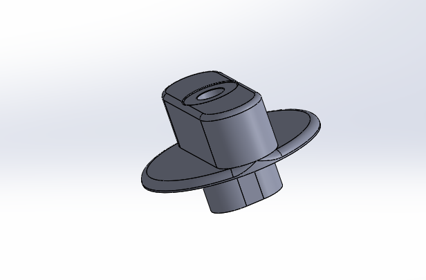
I started by designing a part of my tripod that I broke at the beginning of the class, I actually really needed this part so perfect timing!
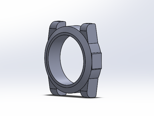
Then I followed a turorial on Youtube because I wanted to learn a little bit more about "sculpting", I ended with this watch dial:
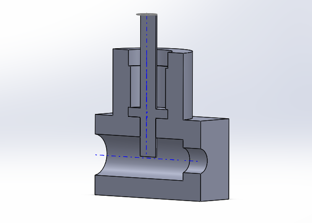
Next step , assembly! This was a simple part but it allowed me to practice how to joint and constraint different bodies:
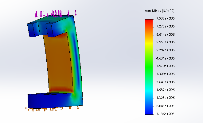
And last thing that I really like about SW, simulations, it is quite easy to test the mechanical and thermical properties of your design, here you can see a compression test on a ABS part that I made:
Autodesk Fusion 360
And this was my best discovery during this class: Fusion 360, it has so many benefits:
I am just going to overview what I've done, it is useless to try to show you all the tools there are so many! Every time you are missing something just type what you want to do on google, there will be a tutorial for you.
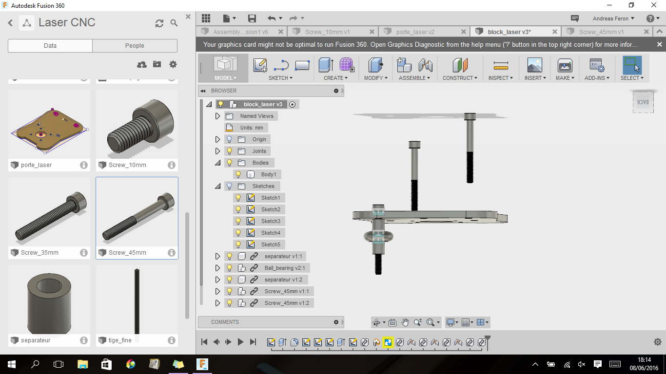
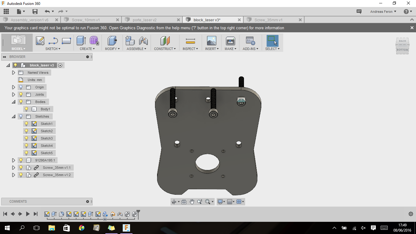
So here you can see me puting screws in a design I made from a DXF I draw on CorelDraw, and here is the best part : I didn't make those screws, I directly imported them from McMaster-Carr, and since they have every mechanical piece you can dream of, it is such a time saver, because let's be honest, knowing how to design a screw is fundamental, but are you really going to design every single screw of your car? Well only if you don't have screws obviously, which you coud try to cast but thats a whole other subject!
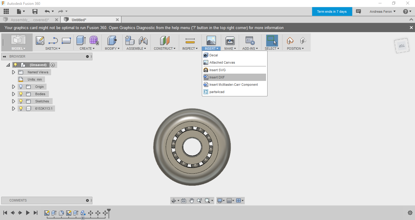
Talking about wheels, there is my final design I came up with to go into my final project (I did prototype like 15 different model of wheels). And once again I imported the bearing from McMaster so I could dedicate all my time working on the good design for the wheel, the perfect equilibrium between the courbature I needed so it could be perfectly blocked on the rail and the capabilities of an Utlimaker to print without support!
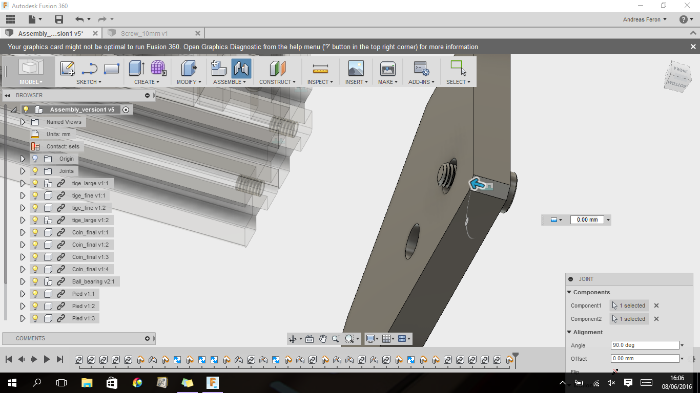
Screws again, this time I had to to the threads:
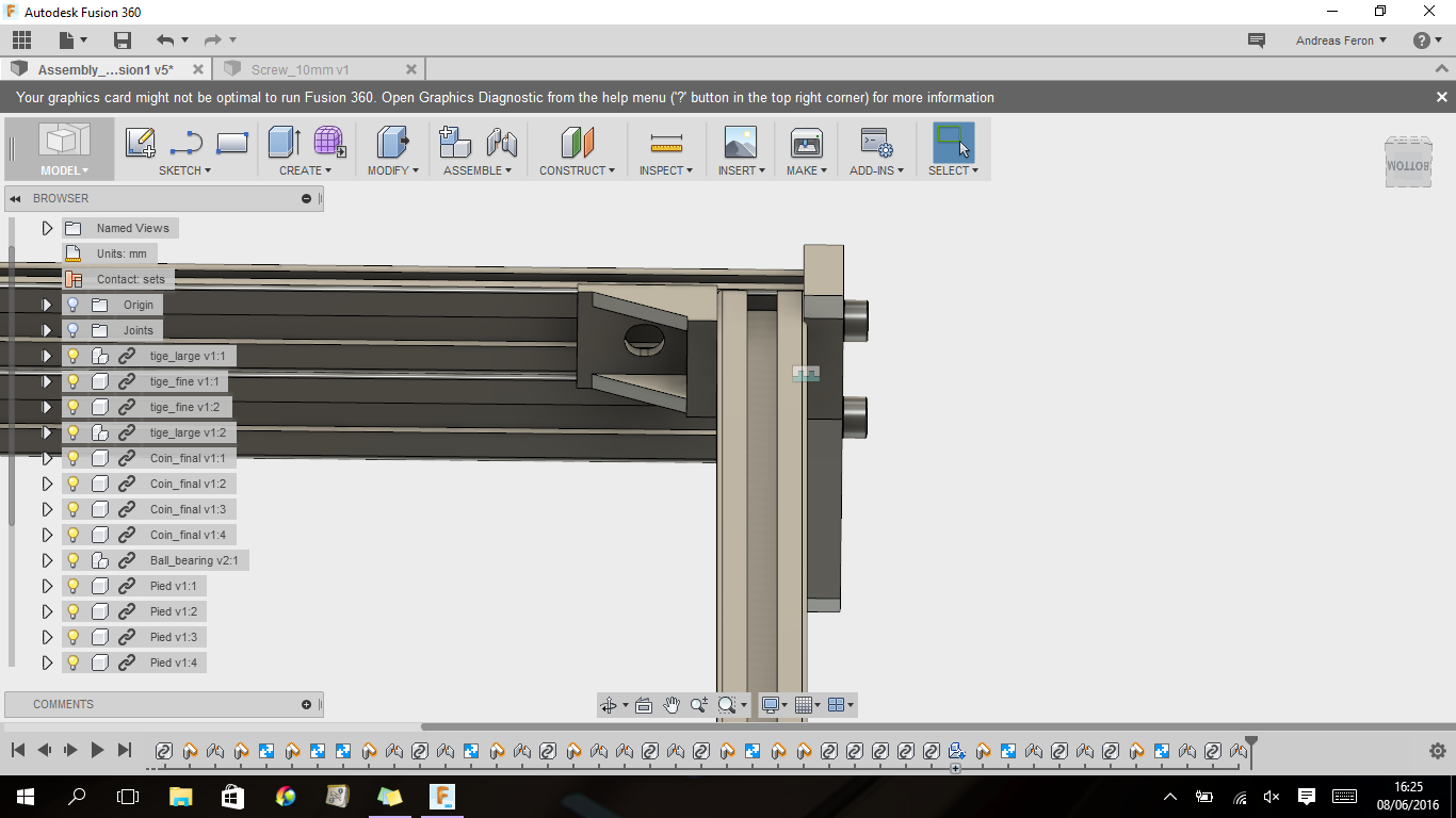
Here you can see the first part of my final project, I thought that corner would do the trick to hold on the bar but when building it I realised I had to add the same piece underneath.
Here is the Y carriage for my final project, the rail goes between those two range of bearings:
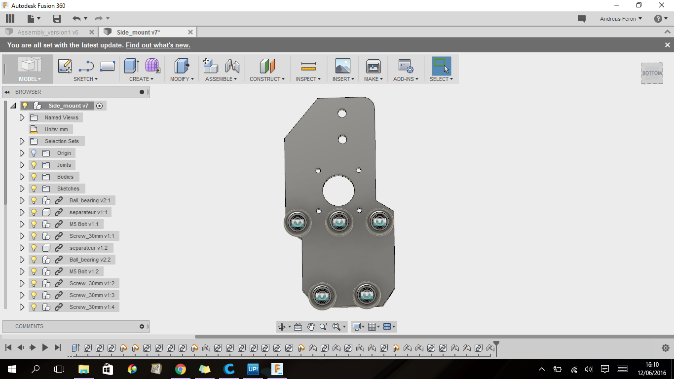
Same system for the X axis:
Thinkercad
My team mate Jean-Francois Arruabarena made me discover this tool at the very beginning of the class and I have to admit that I was a bit sceptical about the utily of such a simple software, but it became my best friend!
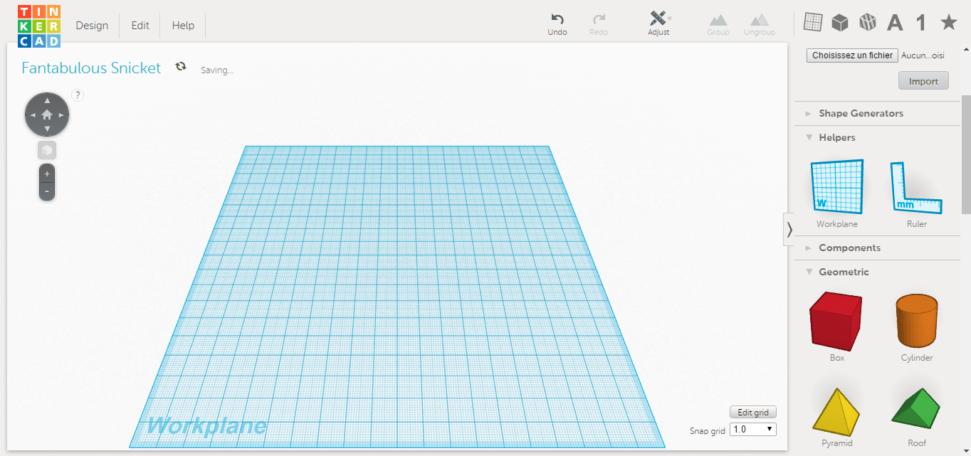
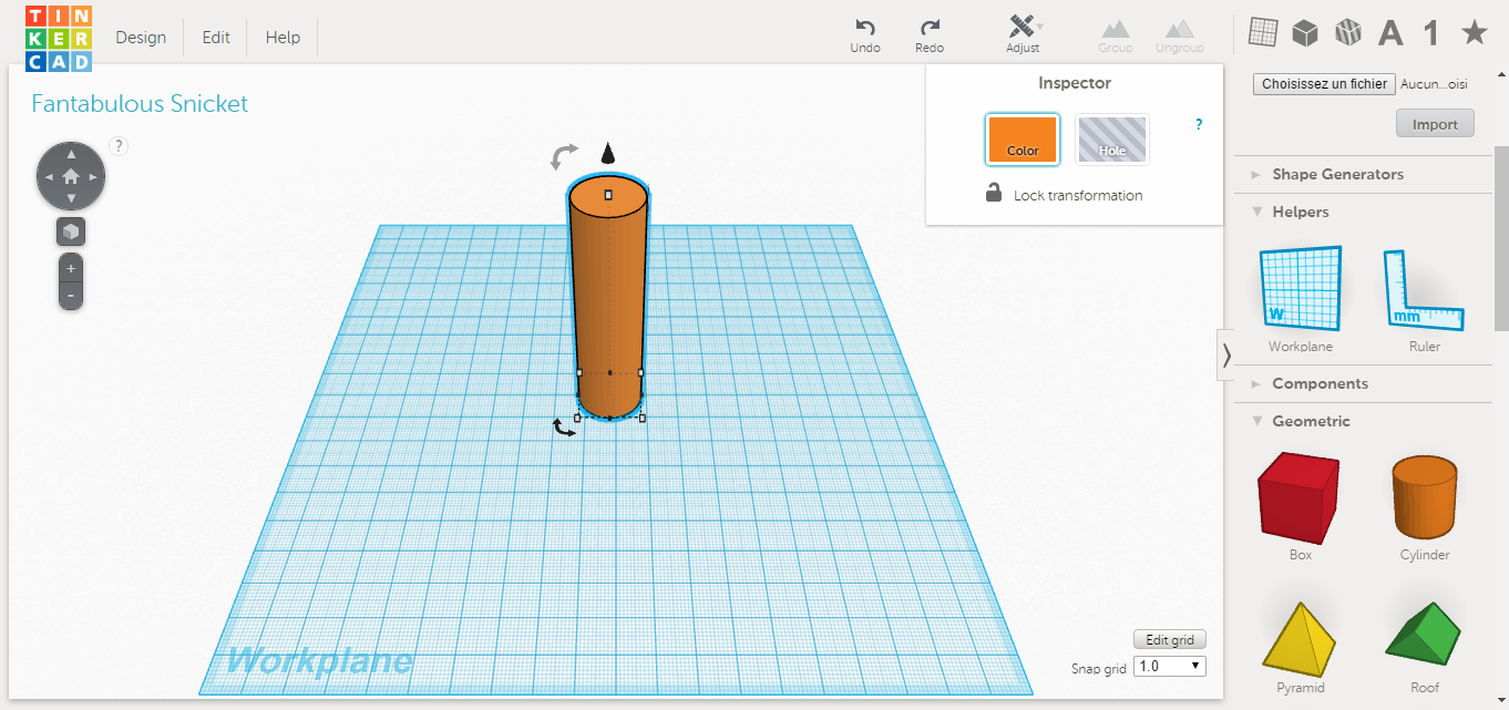
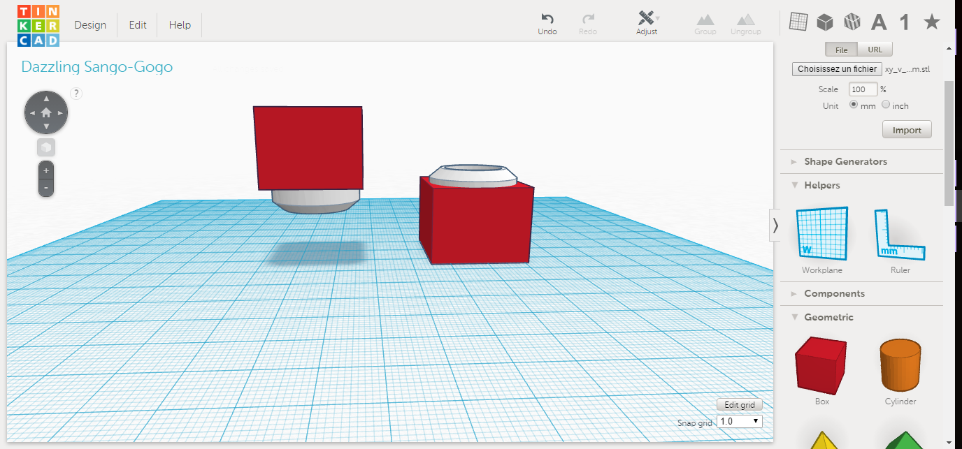
The menu couldn't be simpler:

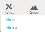
It works by applying boolean operations, so you can add/substract, align, mirror and group volumes.
The cool thing is that you can group and ungroup at any time:
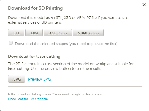
And directly dowload an STL :
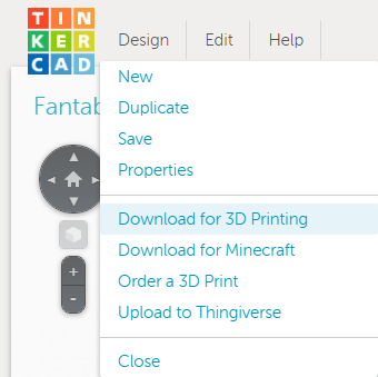
Or even a SVG for a plotter:
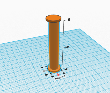
Here you can see a quick design for my final project:
So now when I wanna quickly print a simple thing or readjust volumes in a part, Thinkercad! And I still didnt find a better soft to introduce people to CAD design, they can quickly have some fun and enjoy printing there own piece.
Corel Draw
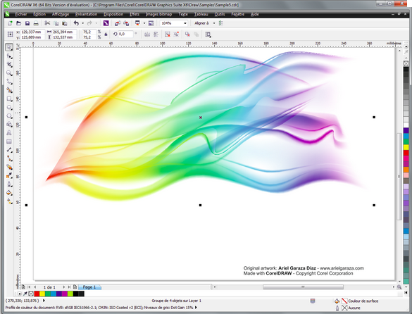
I usually only use CorelDraw to vectorise my files before sending them to a laser cutter or just to convert them in DXF or SVG but I know that it is also a powerfull drawing tool, I just never did something else with it.
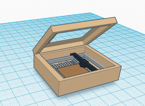
For exemple this piece that I made:
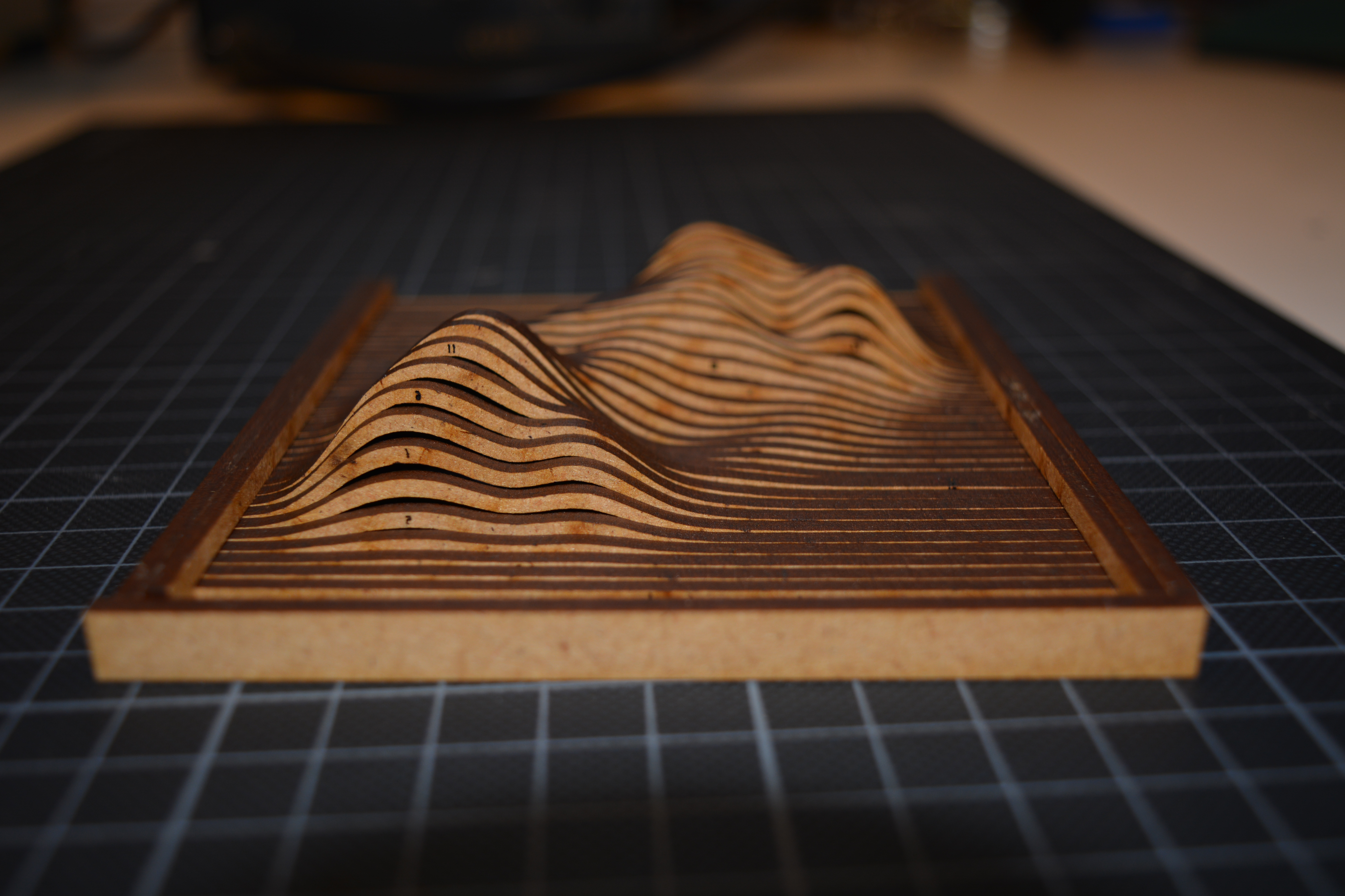
I used 123D make to slice a 3D object that a friend of mine simulated on a super computer, basically it represents the free-energy of a proton in a hydrogenoïde system in 3D (1cm represents 1eV on the Z axis) .
But there was a lot to clean on the file, I had to get rid of the extra lines that 123DMake added and change the colour on the contour so it could be cut with a Trotec. Typically the type of job I do on CorelDraw.
