This module week marks the beginning of taking information we've learned and skills we've developed in previous weeks and synthesizing/implementing them. I am challenging myself this week to use the phototransistor board with an LED and using synchronous detection. Synchronous detection is modulation of a signal so that you can separate it from interferance. My board contains a phototransistor, which reads the amount of light that comes in to convey a signal. Because my board will contain a light-emitter, I will be using synchronous detection to read the amount of light being emitted and reflected by the sensor.


Once my board was milled, I downloaded Neil's light Makefile and .C file. During my programming process in the terminal on Linux, things seemed to be going good: I was able to use my makefile to create the hex and out files; my board does not have a crystal-- so I do not need to set fuses; but when it came time for the board to be programmed, I received a few "error" messages:

This error message came about during my initial attempt at programming. I was unsure what it meant so I googled the message to see if other people ever received this message as well. I found one source that stated: " The AVR was running too slow for the flashing speed, causing it to randomly misunderstand commands".

After I researched my first error message, I chose to go back and just tried to program it again. This was the second error message I received. I have seen it before, so it was not a big deal.


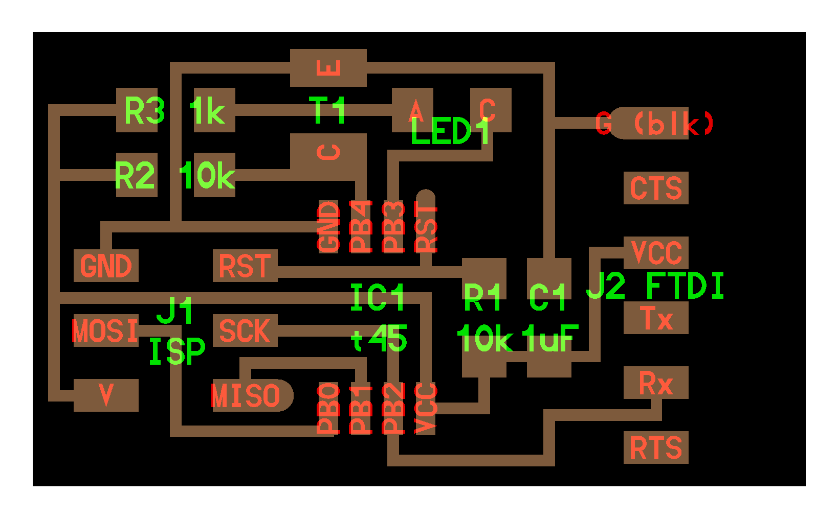
With this message, the LED on my board did come on. I disconnected my board from my programmer, and I noticed the light went off. I had never encountered this before. So I used a multimeter to read the voltage that my board was receiving connected as well as disconnected from my programmer. Between power and ground, my board was not getting the five volts it needed to sustain on its own. i went back to my Eagle board layout and compared it to Neil's board to see what I missed. I realized that I am missing a GND trace from the Emitter side of my phototransistor to GND of my 6-pin header. To resolve this issue to move forward and efficiently have my board programmed, I will solder a wire between the two components.

