Week 4
Electronics Production
The fourth assignment for this course is to make an in-circuit programmer. This requires using a mini-mill to mill away copper on a copper clad board to make a circuit. I then had to learn to surface mount solder (new for me), program the board and test it for functionallity.
This was absolutely amazing to me. I have used large vertical mills, and I could not imagine why I would want to use such a small mill. This is perfect for making circuit boards. It is also a very good way to teach middle and high school students the processes of controlling a CNC mill without the danger, expense, and material cost of using large mills. I am also amazed that all the processes like vinyl cutters, lasercutters, mills and routers are all very similar when it comes to controll. Although I am just starting to learn what the fab modules are, I can see how they solve all kinds of communication problems between software and hardware control!
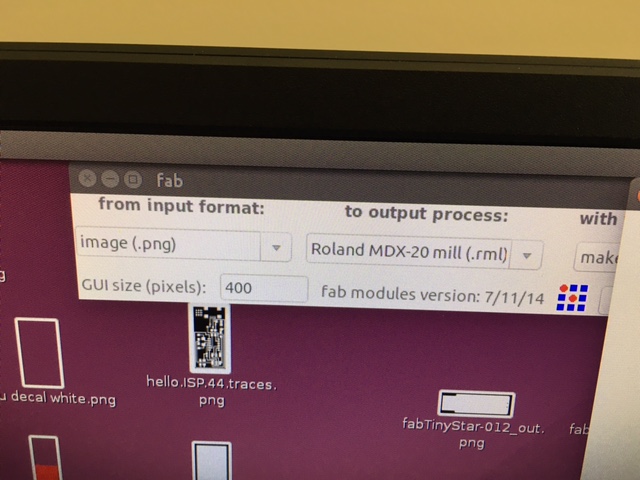
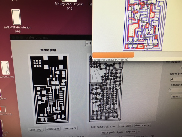
This is a screen shot of the fabmodule as it sends the process to the Roland MDX-20 mill to remove copper from the board.
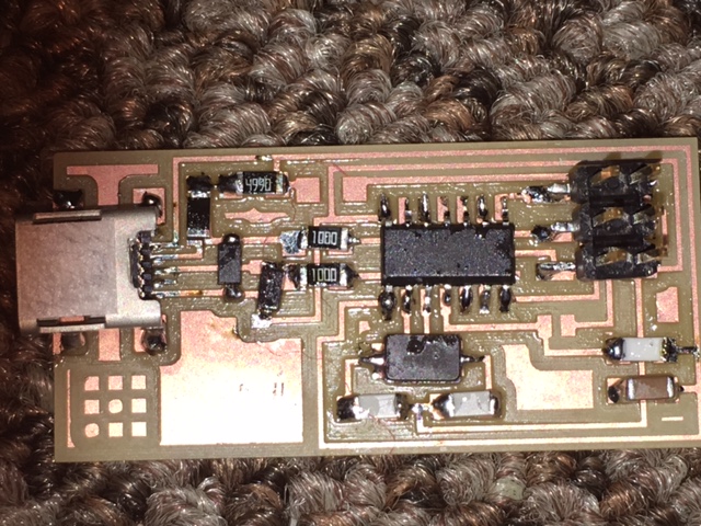
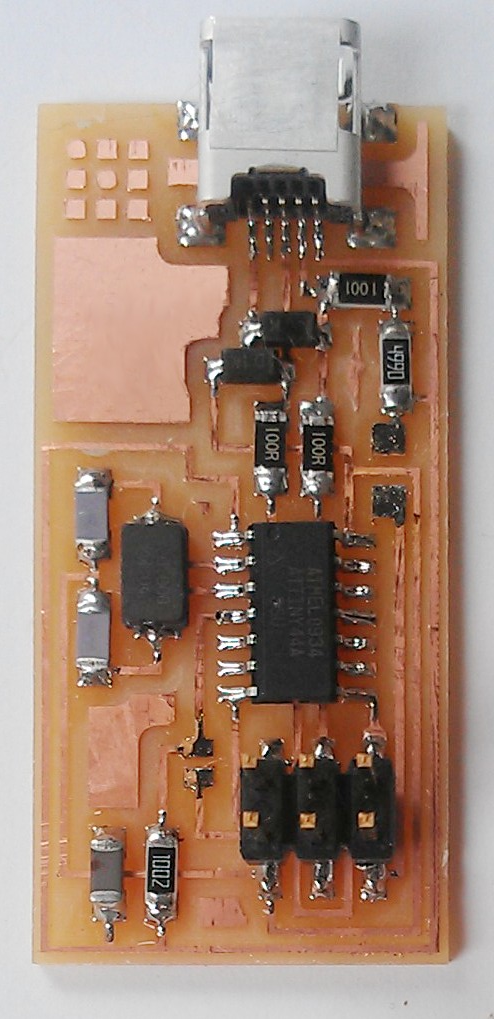
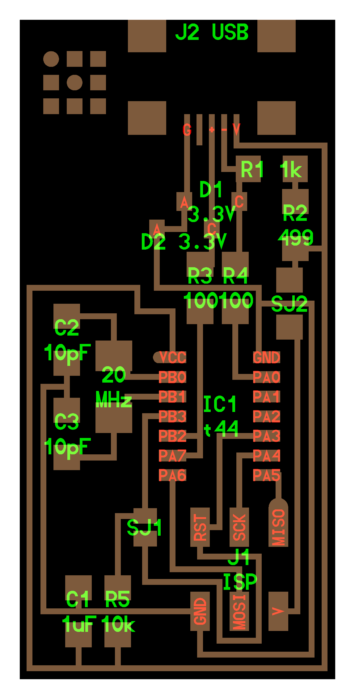
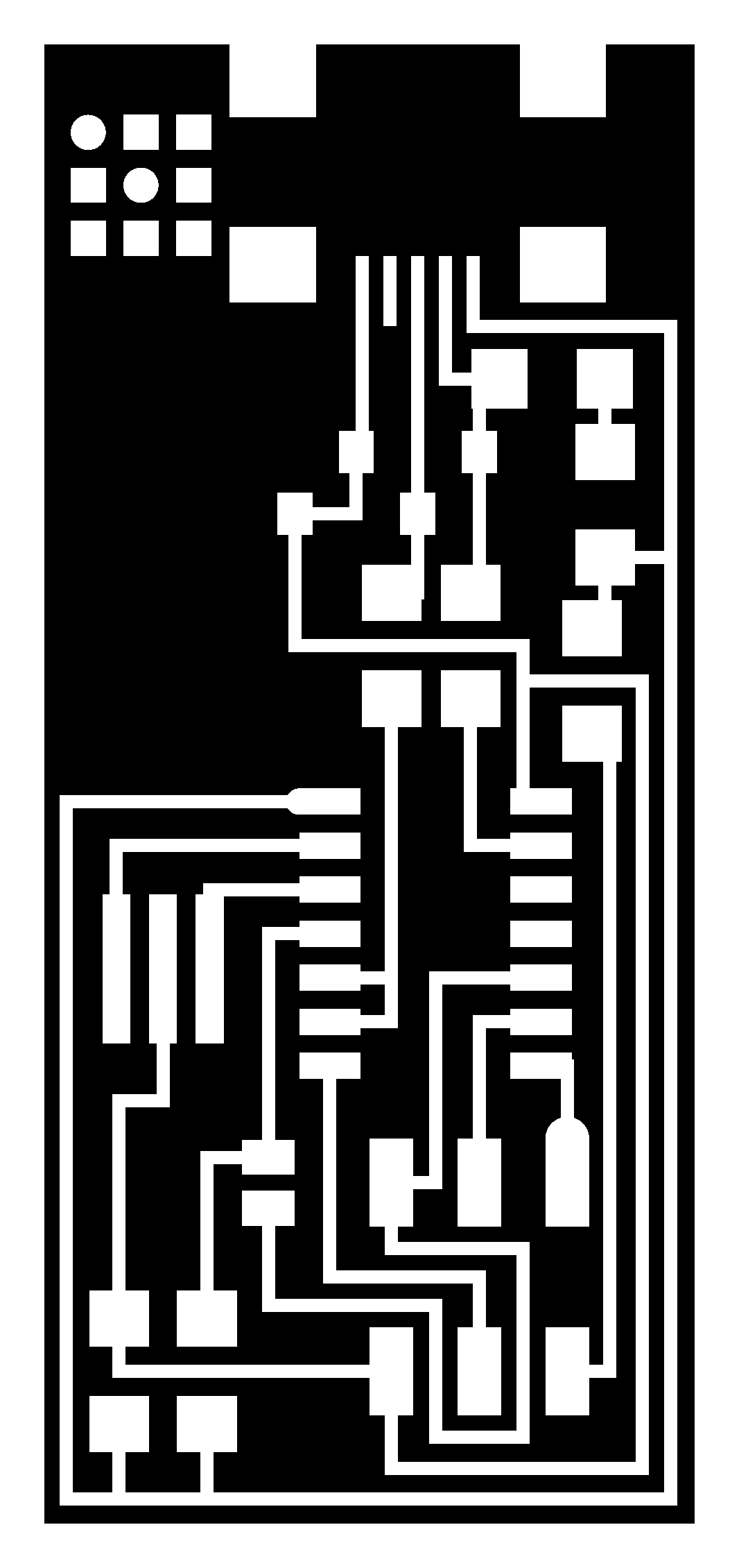
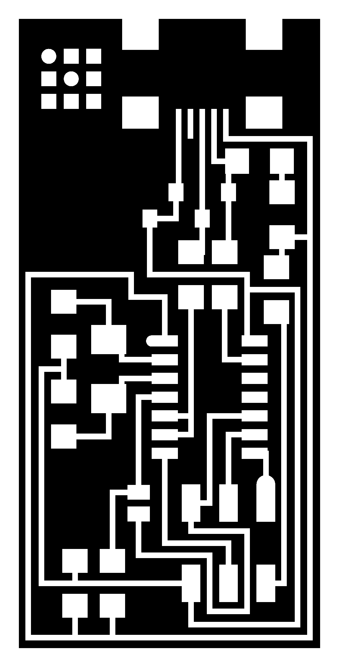
This is the controller board that I milled and then surface soldered.
So, this is what my board looks like. I think it might work, but being away from the lab and therefore my resources for the week, I did not get it electronicly tested. I also did not get it programmed. Hopefully, when I get to class next Wednesday, Matt will help me with the testing and programing.
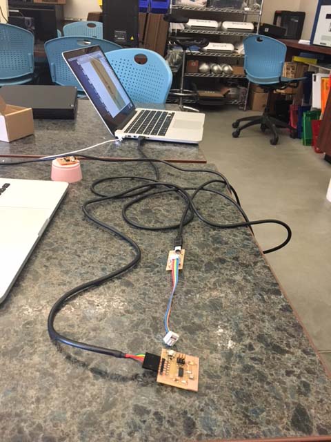
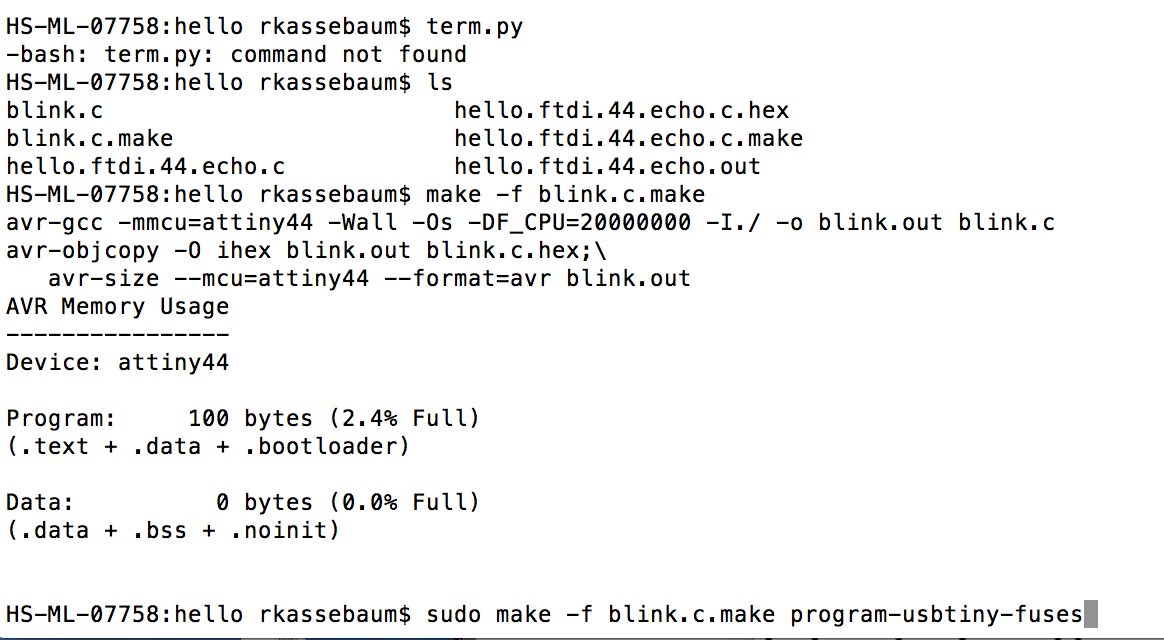
Ok, I returned to the Fab Lab and tested my programming board using the tutorial for setting up the programming files. It did not work. I used a commercial AVR programmer (by XYG)I purchased from Amazon to see if my board was connecting. I got a red light instead of a green light. I examined the board and I suspected either a cold solder connection, or a bridge solder. I resoldered a few suspicious connections...and eukera...green light! I downloaded the modified firmware for Macintosh, compiled the firmware, set the fuses, programmed the board to be an ISP using avrdude and Wooo! Success! I then removed the 0 ohm resistor so I could use it as a programmer to program other boards.

Programming Code
Board programming setup. Click here to see a very short video of the board blinking after being successfully programmed with my ISP Programmer board. If the movie does not play, you can go to the file repository on the left hand side of the browser and find the file slowblink.MOV
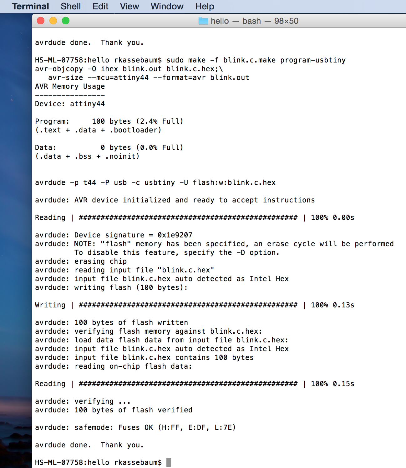
Averdude Programing in Terminal
For a nice video of the completed function board...go to the file repository and view slowblink2.m4v movie.
The programs used to design, test, and program the board are located in the file archive on the left side of the browser. The files used were: Fab ISP programming tutorial, hello.ISP.44.cad,hello.ISP.44.components.png, hello.ISP.44.interior.png, hello.ISP.44.png, hello.ISP.44.res.interior.png, hello.ISP.44.res.traces.png, hello.ISP.44.traces.png