Input devices
Assignment:
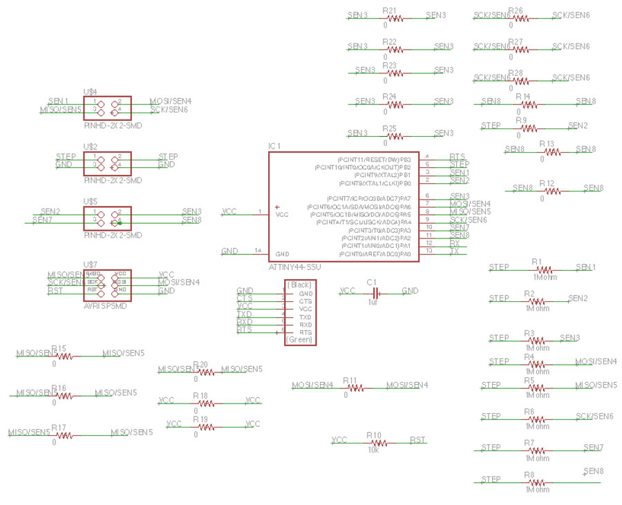
1. Measure something: Add a sensor to a microcontroller board that you have designed and read it.Design the board.
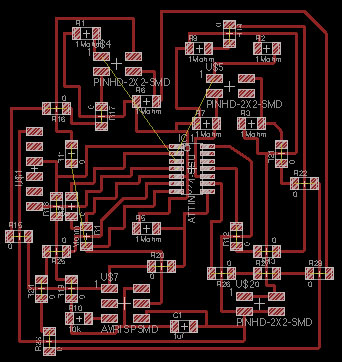
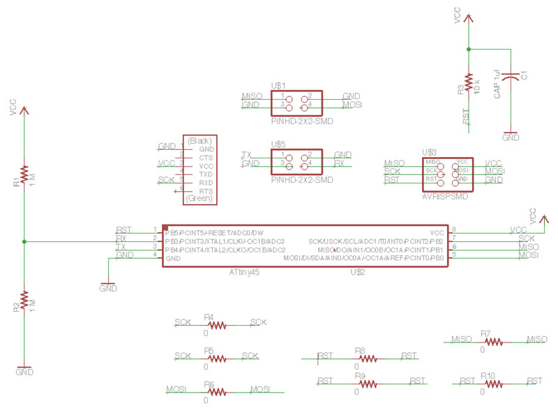
My first trial for this week was try to make the step response touchpad board following the Matt Blackshaw steps. Designing again in Eagle has been a good way for refreshing the skills learned a few weeks ago.
This is my Bill Of Materials (run bom command on Eagle)
CAPACITOR 1uf CAP-UNPOLARIZEDFAB C1206FAB
ATTINY44-SSU SOIC14
RESISTOR 1Mohm R1206FAB -- Eight units--
RESISTOR 10k R1206FAB
RESISTOR 0 R1206FAB -- Nineteen units--
FTDI-SMD-HEADER 1X06SMD
PINHD-2X2-SMD 2X02SMD -- Three units--
AVRISPSMD 2X03SMD
The problem came later, when I learned that you can not use PB pins when you need to read multiple values like time and response, you should just use PA pins. I also used the ATtiny 44, as Matt did, but I was not able to bypass the pins issue. The main issue was in the MUX distribution of the pins. I should keep learning on this issue.
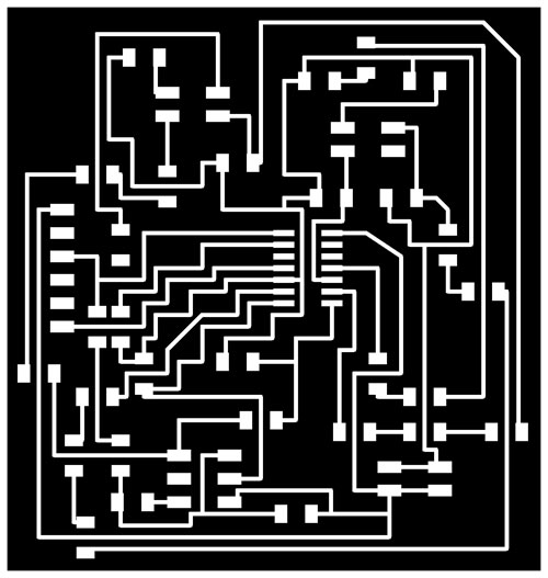
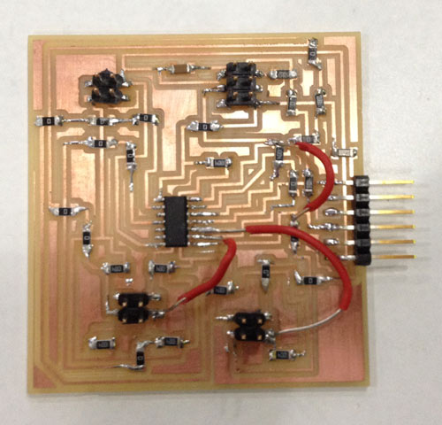
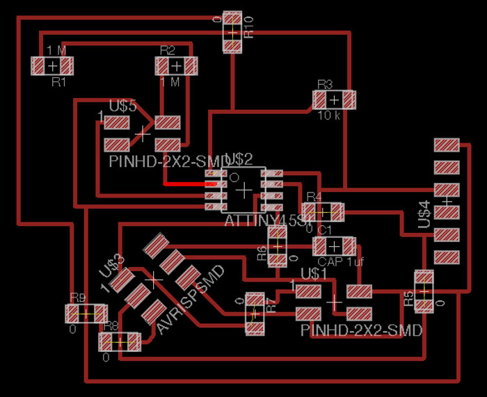
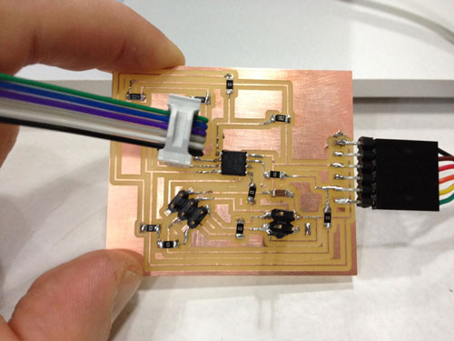
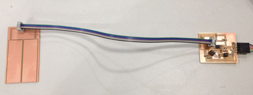
In my design I used a lot of jumpers (0 ohm resistors) for designing fast, but during the stuffing part it was a pain in the ass, soldering all those resistors. And, as you can see in the picture I made some connections with wires. At the end the board was quite messy, but the connections worked. According to the multimeter.
For his project Matt installed Node.js in order to (in Matt's words) "read output from the serial port which is sent to the browser using a WebSocket and visualized using ProcessingJS".
With the NodeJS installed, python-tk, pip2 or pip3 (depending on your version of python) & pySerial. And the libraries: ExpressJS and Socket io I tried to solve the problems but when I was programming the input I came up with tons of errors.
I tried editing the step.c file and change the pins in order to fit with my board design. The PB pins and the PA problem I was comenting earlier, but this didn't work for me. Considering this a failure. I decided to go on and try with an easier step response input.
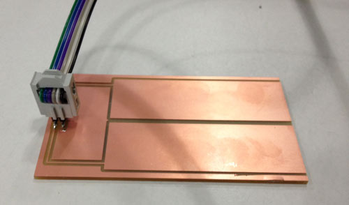
I focused on the step response loading Neil's example. Inspired by Francesca Perona example I wanted to be able to use my programmed board with different capacitive sensors. I designed a second txrx board to connect both boards I used 2x2 header pin.
This is my Bill Of Materials (2nd board)
CAPACITOR 1uf UNPOLARIZEDFAB C1206FAB
RESISTOR 1 Mohm R1206FAB -- Two units --
RESISTOR 10 k R1206FAB
RESISTOR 0 R1206FAB -- Seven units --
PINHD-2X2-SMD -- Two units --
ATTINY45SI SOIC8
AVRISPSMD 2X03SMD
FTDI-SMD-HEADER 1X06SMD
I needed to install python tkinter. Here depending on the version of python you are using, you need tkinter or Tkinter.
The only problem I came up to was that I couldn't make my FabISP programmer connect with the step response input board in order to program it. So I used the AVRISP.
The process is:
- I put all the files needed .c .makefile .py on the same folder. - In the command line navigate on the folder you have located the .c / .make / .py files for the input example.
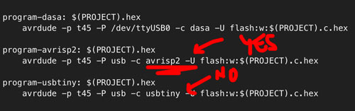
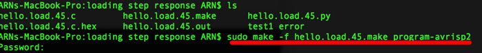
- Type in the comand line: sudo make -f hello.load.45.make program-avrisp2
In order to load the make file into the board I could not use the usbtiny process, like my classmates. Since I was using the AVRISP MKii I needed to change my sudo make -f hello.load.45.make program-usbtiny to avrisp2
This is the option I should use in my command line.This will generate the c.hex / .out files & load the step response.
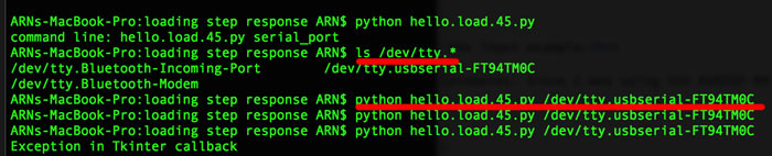
After this, in order to know which was my usb port name connected to my FTDI cable I used the command: ls /dev/tty.*
on the terminal.
And then, for loading the python interface in my computer screen, type:
python hello.load.45.py /dev/tty.usbserial-FT94TM0C
This loaded the python file on my screen and the input sensor was finally reading some data.
This is the video showing how the input sensor is working when you touch it.
Password: inputfablab
Lessons learned: Keep things simple, at least in your first try. You can always make them more complicated later. The differences between PA and PB pins in order to measure things like temperature.Download the files here