Week 08:
Embedded Programming
Objectives
- Read a microcontroller data sheet (zoom ahead to that section)
- some notes on Arduino tutorials
- Program your board to do something, with as many different programming languages and programming environments as possible (see the code experiments)
Software
- Arduino IDE
- C
- Fritzing
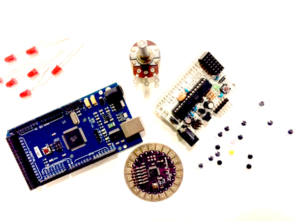
Hardware
- PCB made in Week 06
- Arduino Mega 128
- Lilypad Arduino
Practices
/// Important Vocabulary and Cultural Notes
WHAT IS EMBEDDED PROGRAMMING? It's putting a microcontroller in a system so that it interacts with physical stuff. It is used for physical computing, though it is more specific as a term.
PROTOTYPING. Take it seriously. Phrase of our CNC milling experience: Why let the it-could-be-better get in the way of get-it-done? (addressed inevitably to my dear Hillary, too)
And a song that Arnau has been playing in our moments of collective desperation: Twisted Sisters' "We're Not Gonna Take It" which he sings as "We're Not Gonna Make It."

PRACTICES
/// Neil's Lecture on Embedded Programming
We are going to get to work in the Arduino IDE, a version of C programming language, to make responsive the boards we fabricated in Weeks 4 and 6. I always feel relieved when we are doing electronics and programming, because it is language-based, and language is cozy for me.
/// BLINK, my ARDUINO
It does.
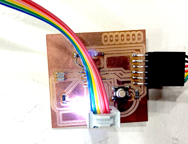
STEPS:
- make a ribbon cable so programmer and board can talk
- find an FTDI-to-USB cable as a translator between the board chip and your computer
- open Arduino open-source program for coding Arduino IDE
- go to preferences and enter the following link in the line that says "Additional Boards Manager URLs":
https://raw.githubusercontent.com/damellis/attiny/ide-1.6.x-boards-manager/package_damellis_attiny_index.json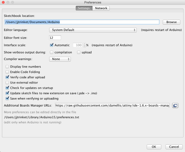
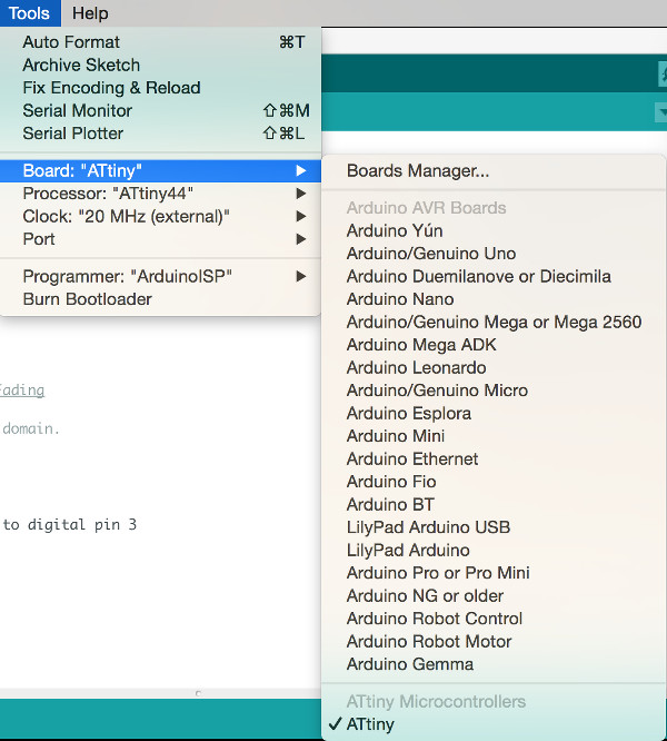
- Check the ATtiny in your Tools / Board menu. Make sure the other factors line up with your hardware:
- go to File/Examples/01.Basics/Blink and open
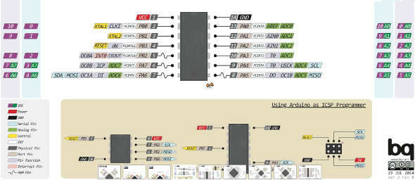
- Is your LED on pin 13? You might need to reference your schematic and do a translation of pin numbers; what Arduino calls pin 13 might not be pin 13 on your board; you'll need the diagram in PighiXXX. Page 2 of the data sheet will show you the pinout of your processor, but it won't show you what the Arduino IDE calls the pins of your processor.
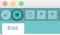
- correct the pin number and upload the sketch to your board using the upload icon in the programming window:
- adjust frequency in the two instances of this line:
delay(1000); - If frequency seems off, go to Tools/Burn Bootloader to synchronize your crystal with the clock you've named in Arduino
FILES
/// ARDUINO TUTORIAL w/ Guillem
Guillem went through the history of computing and brought us up to date with where the Arduino is (with some good industry gossip on the tiff that led to the split of Arduino / Genuino). He generously shared his presentation.
It was a lecture + practicum: nice format. We uploaded some of the basic sketches to our boards. I had to do some cobbling to get a working kit; my parts box is filled with non-standard Arduinos and various unmarked things.
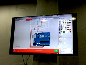
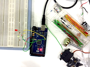
DIGITAL TO PHYSICAL. On the left is the model in Fritzing, a program with a virtual breadboard. On the right is an actual breadboard imitating the Fritzing diagram.
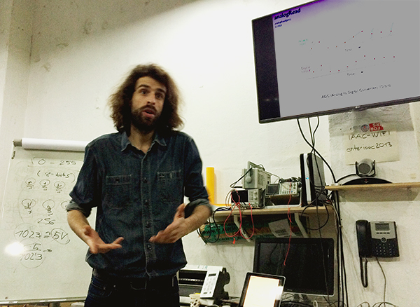
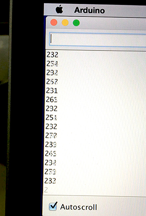
READING SERIAL PORTS. It was cool to see what Guillem called "the noise of the universe" flicker on the serial-read window when there was a jumper in the associated port that was not connected to ground. The picture below is the measurement on an AA battery. The number being read is converted to a corresponding voltage with the following logic:
- Zero scrolls on ground. That's the minimum of the scale. 1023 scrolls on 5V. That's the maximum of the scale (it's actually based on 1024 bits, which is 2 to the tenth, but you don't count zero as a number).
- Take the serial window reading, times 5 and divide by 1023 to get a voltage.
5x/1023 = voltage - In the following picture, "235" translates into 1.15V, which makes sense for a used AA battery.
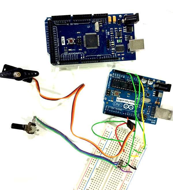
/// ARDUINO TUTORIAL w/ Ferdi
We looked at how to control the following in the Arduino IDE:
- AnalogInput and the serial monitor
- ReadAnalogVoltage
- toneMelody with a pitch file and piezo speaker
- Fading / PWM with two LEDs
- potentiometers controlling light and sound
- LDR (light-dependent resistor)
SOME NOTES:
- There are many loops. We are mostly dealing with "for" and "why" loops.
- Global variables are defined outside the loop. Variables defined within the loop are not acknowledged by the set-up.
- Analog pins are only input. AnalogWrite is actually PWM. It uses a capacitor to smooth out the difference between a price-y true analog out and one that's faked with PWM. Real analog is expensive. Your graphics card in the computer can do it, but not your phone. Your phone is simulating analog (voice output) by using PWM frequencies of gigaHertz. The human ear can hardly notice the difference (except when truly surprising information comes across, such as "I think I love you," and you have to ask "What???"). The Arduino uses a 555 timer chip to put out a square wave that simulates analog output. It also uses a capacitor. Using a capacitor on a PWM signal is, using the water metaphor for current, like having a tank that lets water out in spates and taking your measurement at a sink that is at a constant level on the spitting flow. Thanks, Arduino, for doing that for us.
- Here's a +1 integer definition in a for loop:
int thisNote = 0 < 8; thisNote++;~ the last thing means "thisNote, then add one; in other words, each time the loop runs, you increase by an integer of one- A melody is an array composed of all the things in that line of code.
- PWM, pulse-width modulation
- Re: motors, you can run them Hi / Lo (on / off), or you can run them at varying speeds with PWM.
- Then they run at a "duty cycle," which is a percentage expressing for how much of one frequency cycle the signal is "on" or Hi. A 30% duty cycle means the signal is Hi for 30% of the on/off flicker cycle of a PWM sequence.
- Use PWM for motors, heating control, light (and more).
- Coils use electronic oscillation with PWM to generate sparks.
- You can use PWM frequencies to tell a servo where to put itself (low to one side, middle a middle position, high goes over to the other side).
- To get a potentiometer on an analog pin to talk to a digital pin doing something, you need to translate the number systems. Analog is from 1 to 1024; if you're using light or color, it's going to from 0 to 255. You use a value map function.
val = map (val, 0, 1023, 0, 255)
Here's a program file for using an LDR or potentiometer to vary an input signal into a digital output, in this case into a modulating pitch tone.
Playing with code
Some aspects of Arduino programming have caught my attention, such as pushbutton debouncing, millis timing, and if - else logic. I also wanted to make an Arduino lesson that led people to connect embedded programming with the ways things function in a city. Here follows some commented code exploring those things ~
- PUSHBUTTON
What is debouncing?
When two pieces of charged material, such as copper, are pushed together, the physical stuff touches and un-touches differently from its charge. This means that a physical pushbutton generates a messy input signal. To rectify this, you can use code. The code tests the state of the button as HI or LO (ON or OFF), waits 10 milliseconds, then tests again. It keeps doing this till the two tests come out with the same result, meaning the button has settled into one state, and is no longer unstably jiggling between more than one state./* * Switch and LED test program from Adafruit (based on the 5-LED program). * See: http://www.ladyada.net/learn/arduino/lesson5.html */ // This turns on 2 LEDs when button is pressed, then turns them off when button is pressed again. // Includes serial read-out of the state of the LEDs. // Includes 10ms debounce delay as well as a validation statement for debounce. int led1Pin = 5; // LED is connected to pin 5 int led2Pin = 6; // LED2 is connected to pin 6 int switchPin = 1; // switch is connected to pin 1 int buttonState; // variable to hold button state int val; // variable for reading the pin status int val2; // variable for reading the delayed/debounced status int lightMode = 0; // Is the light on or off? void setup() { pinMode(switchPin, INPUT); // Set the switch pin as input pinMode(led1Pin, OUTPUT); // Set the LED pin as output pinMode(led2Pin, OUTPUT); // Set the LED2 pin as output // Serial.begin(9600); // Set up serial communication at 9600bps buttonState = digitalRead(switchPin); // read the initial state } void loop(){ val = digitalRead(switchPin); // read input value and store it in val delay(10); // 10 milliseconds is a good amount of time val2 = digitalRead(switchPin); // read the input again to check for bounces if (val == val2) { // make sure we got 2 consistent readings! if (val != buttonState) { // the button state has changed! if (val == LOW) { // check if the button is pressed if (lightMode == 0) { // light is off lightMode = 1; digitalWrite(led1Pin, HIGH); digitalWrite(led2Pin, HIGH); // Serial.println("lights on"); } else { // the button is -not- pressed... lightMode = 0; digitalWrite(led1Pin, LOW); digitalWrite(led2Pin, LOW); // Serial.println("lights off"); } } } buttonState = val; // save the new state in our variable } - MILLIS TIMING
Millis timing is a way to avoid the microprocessor delay inherent in the way the Atmel chips function. It uses C programming. The following code is heavily commented by me, and it's derived from the Adafruit tutorials on the subject.
/* Blink without Delay Turns on and off a light emitting diode (LED) connected to a digital pin, without using the delay() function. This means that other code can run at the same time without being interrupted by the LED code. The circuit: * LED attached from pin 13 to ground. * Note: on most Arduinos, there is already an LED on the board that's attached to pin 13, so no hardware is needed for this example. created 2005 by David A. Mellis modified 8 Feb 2010 by Paul Stoffregen modified 11 Nov 2013 by Scott Fitzgerald commented June 2017 by Janaki Ranpura This example code is in the public domain. http://www.arduino.cc/en/Tutorial/BlinkWithoutDelay */ // constants won't change. Used here to set a pin number : const int ledPin = 13; // the number of the LED pin // Variables will change : int ledState = LOW; // ledState used to set the LED // Generally, you should use "unsigned long" for variables that hold time // The value will quickly become too large for an int to store unsigned long previousMillis = 0; // will store last time LED was updated // Setting previousMillis to 0 means you have a variable in the timing count formula below (a simple subtraction formula) // that does the equivalent of re-setting the countdown to "full," since nothing is subtracted from the whole interval. // constants won't change : const long interval = 1000; // interval at which to blink (milliseconds) void setup() { // set the digital pin as output: pinMode(ledPin, OUTPUT); } // can name any output here that will repsond to the state reading, in this case "ledState" void loop() { // here is where you'd put code that needs to be running all the time. // check to see if it's time to blink the LED; that is, if the // difference between the current time and last time you blinked // the LED is bigger than the interval at which you want to // blink the LED. unsigned long currentMillis = millis(); if (currentMillis - previousMillis >= interval) { // save the last time you blinked the LED previousMillis = currentMillis; /* This logs the time as the current time by making them the same thing. */ // if the LED is off turn it on and vice-versa: if (ledState == LOW) { ledState = HIGH; } else { ledState = LOW; } // set the LED with the ledState of the variable: digitalWrite(ledPin, ledState); /* This says, on this pin send this command if the time check says it is time for things to change. */ } } - IF - ELSE LOGIC
I was trying to figure out why
ifdoes not always take anelf-- I mean anelse. And then how doeselse iffit?if ((condition) && (condition))
{
action;
action;
}
else if (condition)
{
action;
action;
}
OR, THE SIMPLER CASE, structured for a binary choice:
if (condition == this)
one action;
else (condition == that)
one action;
Iftests a condition; if it is not true, thenelseapplies. If there are more than two options, then the code testsifor anything else, which iselse if. I am trying it out here:/* based on this work code by Janaki Ranpura, Fab Lab Barcelona, 20170621. */ #include
// Parameter 1 = number of pixels in strip // Parameter 2 = Arduino pin number (most are valid) // Parameter 3 = pixel type flags, add together as needed: // NEO_KHZ800 800 KHz bitstream (most NeoPixel products w/WS2812 LEDs) // NEO_KHZ400 400 KHz (classic 'v1' (not v2) FLORA pixels, WS2811 drivers) // NEO_GRB Pixels are wired for GRB bitstream (most NeoPixel products) // NEO_RGB Pixels are wired for RGB bitstream (v1 FLORA pixels, not v2) Adafruit_NeoPixel strip = Adafruit_NeoPixel(4, 6, NEO_GRB + NEO_KHZ800); // IMPORTANT: To reduce NeoPixel burnout risk, add 1000 uF capacitor across // pixel power leads, add 300 - 500 Ohm resistor on first pixel's data input // and minimize distance between Arduino and first pixel. Avoid connecting // on a live circuit... if you must, connect GND first. // part Janaki wrote starts here: // // constants, things that don't change const int blank = 0; // calling "off" as blank const int minBright = 5; const int maxBright = 191; // (75% brightness; 100% is 255) const int pixPin = 6; const int motorPin = 7; // variables, things that change int pixState = blank; // int motorState = low; long previousMillis = 0; long interval = 3000; // using 3s for now instead of actual 25 minute timing, so I can test the system ... // initializing void setup() { strip.begin(); strip.show(); // initialize all pixels to "off" // pinMode (pixPin, OUTPUT); // I can comment out this pin assignment without an effect on the Pix 0 experiment. // pinMode2 (motorPin, OUTPUT); } // what to repeat over and over and over ... void loop() { uint16_t j; // declare the variable j unsigned long currentMillis = millis (); if ((pixState <= minBright) && (currentMillis - previousMillis >= interval)) { // using pixState == minBright does not work here, as it does not take "blank" into account previousMillis=currentMillis; // if (pixState >= blank) { // pixState = minBright; for (j >= minBright; j < maxBright; j++) { // j = brightness of NeoPix strip.setPixelColor(0 ,0 ,0 ,j); strip.setPixelColor(3 ,0 ,0 ,0); delay(20); // this is the code that elongates the period of brightening; it has to come BEFORE "show" strip.show(); } } else (pixState >= minBright); { for (j = maxBright; j > minBright; j--) { // j = brightness of NeoPix strip.setPixelColor(0 ,0 ,0 ,j); delay(10); // this is the code that elongates the period of brightening; it has to come BEFORE "show" strip.show(); // here was some code I used to try to reset an intial condition to trigger the rest of the loop ... unneeded when my code was better-formed // strip.setBrightness (0); // strip.begin(); // experiment in resetting ... effect is that the very first iteration it works: the pixel fades up and fades down ... // strip.show(); } } } - STOPLIGHT GAME
See comments in the code for more explanation ~
/* looking at how to transfer LDR info to light up an LED, variably
// see here: https://diyhacking.com/arduino-ldr-sensor/
/*
Making a Stoplight-style system.
This project allows you to automatically turn on and off LEDs
depending on the light level near the
LDR (Light Dependent Resistor). The LDR senses light intensity.

Connections:
LDR --> One leg to Vcc and the other to both analog pin 0 and to the GND via 100K resistor
LEDs --> Connect one pin of the coil to digital pin 2 and the other to GND.

*/

// right now, this is modeling a traffic system where the light is red until a car's headlights hit a sensor;
// then the light turns green

int sensorPin = A0;   // select the input pin for ldr
int sensorValue = 0;  // variable to store the value coming from the sensor
int greenPin = 8; // green LED connected to digital pin 8
int redPin = 11; // red LED connected to digital pin 11

void setup() {
  pinMode(greenPin, OUTPUT); //pin connected to the relay
  Serial.begin(9600); //sets serial port for communication
}

void loop() {
  // read the value from the sensor:
  sensorValue = analogRead(sensorPin);
  Serial.println(sensorValue); //prints the values coming from the sensor on the screen

  if(sensorValue > 500) //setting a threshold value
  {
  digitalWrite(greenPin,HIGH); // turn green LED ON
  digitalWrite(redPin,LOW); //turn red LED OFF
  }
  else
  {
  digitalWrite(greenPin,LOW); // turn green LED OFF
  digitalWrite(redPin,HIGH); // turn red LED ON
  }
  delay(100);
}
/// Comments on Workflow
Maybe this is a great week to have tried out a new workflow for documentation: the daily log. This, unfortunately, is how the week worked out:
- PREDICTED WORKFLOW this week:
- read data sheet for chip
- choose what the board does
- find the code
- load it
- debugging
- finish documentation
- ACTUAL WORKFLOW:
- design shelves
- design shelves
- design shelves
- lasercut
- redesign shelves
- programming
So it's been chaotic in terms of time management, but through documenting based on each day, I have a coherence organized by hours instead of by any summarizing logic: Gregorian rather than Dewey. During Neil's Wednesday lecture, we looked at the site of Eva Korae, a Cypriot furniture maker in Amsterdam, and she used this method of daily logging.
I am not sure it suits me, because it feels so far like it has less room for narrative inventiveness, which is part of my joy. The daily log is, however, more incremental and therefore less stressful. By the end of the week, it seems I am getting more habituated to it. It feels like every day could make a whole page; this is bad. The level of detail for a contemporaneous account seems excessive (for me, for my bad loquacious habits). Concluding observations at the end of this endless page.
REVISION 20160628. Combing this whole gamut into different chapters, separating the milling and the electronics onto their respective pages. Abandoning fidelity to the idea of a "week's work." It just confuses the ability to reference.
/// visit to Museu del Disseny
Terrific inspiration for final projects, esp on the floor of product designs ~ and in a very exciting new public space. Plaça de les Glòries Catalanes is so multi-used that it looks like an architect's pie-in-the-sky rendering come to life.

25 Mar 16. Friday.
Easter in Barcelona!

28 Mar 16. Monday.
/// data sheet for Atmel's ATtiny microprocessor
This doc is docked here.
INTERESTING THINGS I NOTED:
- Data Retention: 20 years at 85° C / 100 years at 25°C
- Although The Art of Electronics explains that a pull-up resistor keeps the circuit at a logic high even when no externally connected devices are active, it does not help that much, as I don't yet really know what the stuff called "logic" is, attractive and popular as it is
- Atmel site elaborates many things, like using wifi communication with these chips as well as capacitive touch
- The four things the CPU does:
- access memories
- perform calculations
- control peripherals
- handle interrupts (or overrides?)
- "Harvard architecture" is about keeping program and memory on separate buses. Here is a good explanation:
In order to maximize performance and parallelism, the AVR uses a Harvard architecture – with separate memories and buses for program and data. Instructions in the Program memory are executed with a single level pipe lining. While one instruction is being executed, the next instruction is pre-fetched from the Program memory. This concept enables instructions to be executed in every clock cycle. The Program memory is In-System Reprogrammable Flash memory. - A lot of talk of doing things in a single clock-cycle. Also calling up instructions in a queue so as to use consecutive clock cycles. This is obviously a big deal ...
- It can do interrupts, and the data sheet explains how.
- One of my favorite phrases re: EEPROM programming mode bits: "Reserved for future use." It makes the future seem like a person who is in the present and needs his bits.
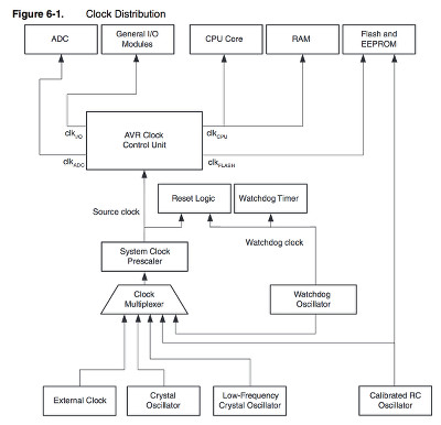
- The big deal of the clock. I hadn't considered the significance of synchronization for enabling the existence of the computer. Direct from train station clocks to microprocessors.
- A lot of clocks in the AVR microcontroller:
- So many functions have to do with clocks: reset, sleep, interrupt, synchronization ...
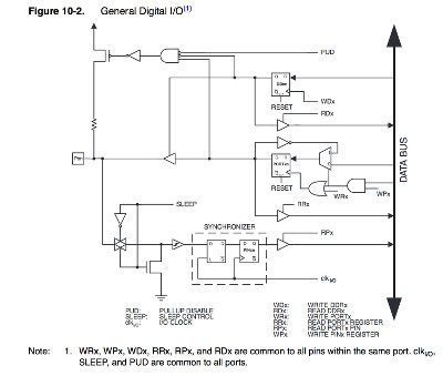
- I/O - This is mostly what we care about: the tool end:
- If I were data, would I say "I'm on pins and registers" to express my enthusiasm?
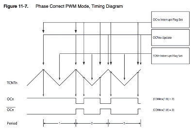
- Logic. Very pretty:
- Looking at all these timing diagrams, the nature of time reveals itself a little: that it is relative (counting needs the friction of another time code to have a countable reality), and that the regularity of a tick-tock is merely an mathematical substitute for the actual reality of time, which, as a lived, thing, is not homogenous.
- I understand nearly nothing about section 14, USI; and section 15, Analog Comparator.
- Fuse bits and lock bits. Lock bits are locked. Fuse bits are writable bits.
- SERIAL PROGRAMMING (ISP). In-system programming (ISP), also called In-Circuit Serial Programming (ICSP), is the ability of some programmable logic devices, microcontrollers, and other embedded devices to be programmed while installed in a complete system, rather than requiring the chip to be programmed prior to installing it into the system.
- tons of charts about frequency, voltage, and current
- index, vocab (for programming), and parts numbers
- footpads
- NB :: hyperlinked TOC is at the end, not the beginning, of the document
21 Mar 16. Monday.
/// recitation: Machines that Make by Nadya Peek
Excited to hear Nadya as she seems to be quite a badass lady.
Some questions Nadya posed and comments she made:
- What we're talking about: "personal digital fabrication: automation for low volume production"
- Are we doing the right thing just by increasing access to FabLabs? There might be a better approach.
- Look at the progression of non-industrial production in light of the timeline of mainframe to personal computer
Nadya considers the example of the cheap Modela. It's successful in terms of being able to be made in a FabLab, but in a way it's not that successful in terms of a goal of light and fast production. It requires:
- using Inventor
- exporting the .dxf
- creating toolpath
- sending toolpath to a processor
- buy parts off the shelf
- design circuit boards for controlling motors and spindle
- g-code interpreter programmed in C
- another toolpath planner that streams to g-code interpreter, written in Javascript and Python
So, in a way this cheap Modela is not an example of big change because it requires so many tools and skills to make. It's one FabLab working slowly to learn to make one machine that doesn't work that well.
How to do it without thinking personal scale is just a smaller cheaper version of industrial scale?
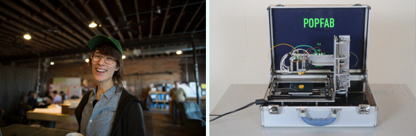
Consider PopFab. Modularity, portability. A machine that becomes a kind of lego system, where units plug together. Where you can prototype in cardboard. We'll be looking into this next week.
What do you lose with modularity? The ability to extend a kit into more complex designs.
For now, remember: if you see something that could be done better, you are the person who could make it better.
29 Mar 16. Tuesday.
/// Meta-observations
WHAT I THINK ABOUT THIS METHOD OF DOCUMENTING. It makes less sense to my brain, finally, to organize by day rather than by theme. It's nice (and sometimes not nice!) to see where the time goes; however, it's more fluid to keep going along an idea than along a 24-hr timeline. And the themes of the pages get all messed up.
The daily notes can be my personal toolkit to make the final week's log. This way, even if I expire suddenly, my notes will be in order.
BTW, if I do notes at the times things are happening, they come out very whiny. I seem to feel I'm struggling I'm a lot while in it. Though this is interesting to observe on a personal level, it's simultaneously unflattering to read as well as boring.
I will go back to my previous method: more of a weekly summary than a daily blow-by-blow.