Week.06 Electronics Design
From hello-world board to a Led and Button
The assignment for this week was redesignin form zero the hello-world board and one button and one LED.
First of all it is necessary to watch this two tutorial videos
and to read a tutorial page from the Fab Academy 2016 English Tutorials Electronics Design - Eagle
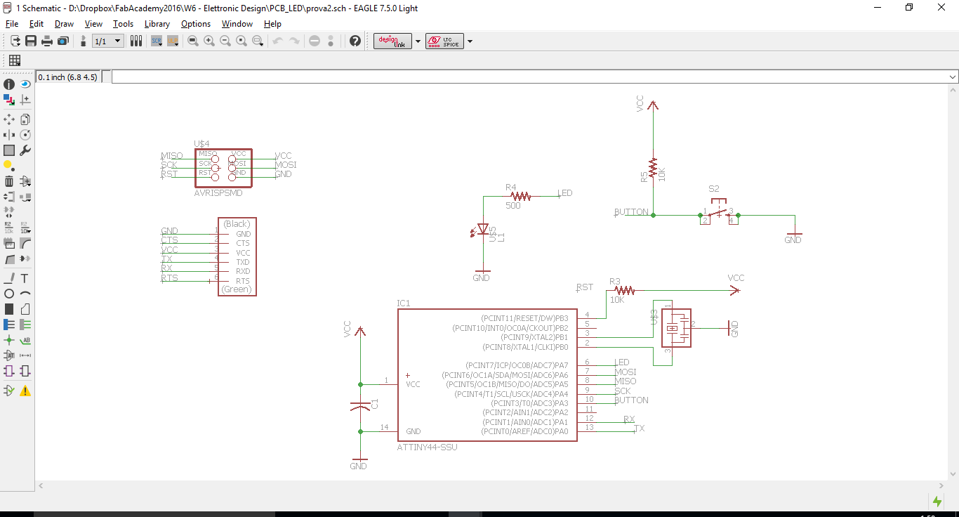
After installing EAGLE under the guidance of Ferdi, I started designing my own boards.This is the schematic:
Autorouter
For a busy guy like me it was too interesting trying to find a "shorter way" to make a PCB traces. For this reason I decided to spend few time trying the Autorouter command.
The reasult was not that bad. The most complete result of autorute tools got to 87.5 %, but unfortunately it was not complete with no possibility to finish manually.
I decided to follow the rest of the group and to do the trace "by hand".
Traces
It is necessary to connect all components in in order to eliminate the yellow track indicating that components are not properly connected.
After few attempts,I reached the result: no yellow line reporting mistakes.
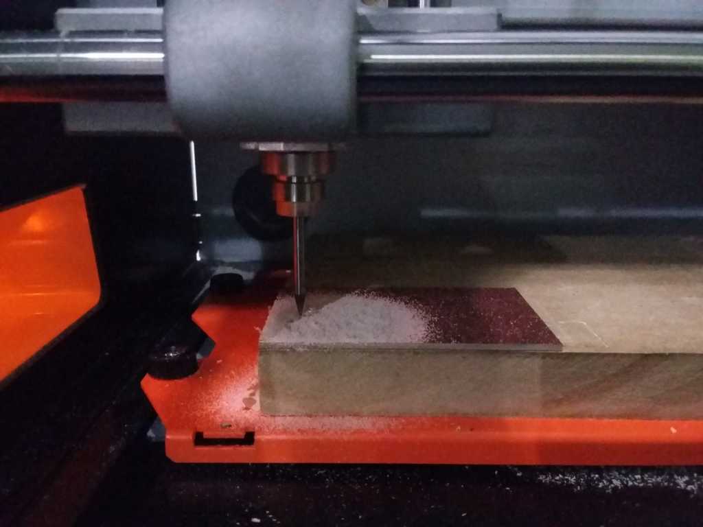
Milling with Roland Modela SRM20
I have decided to realize only the basic card because I missed last friday classes due to the fact that I was busy with my job and that for me elettronic field is a completly new topic. Maybe it doesn't seem a great result, but there is a first time for all, and that's mine!
By a Fab Modules I prepare the Gcode as I already did in a Week.04. This time I am using a Modela SRM20 and VPanel
Final Imagine of the board
Source Eagle Files
Hello LED Schematic
Hello LED Board
Copyright © Elia De Tomasi 2016