
Machine design
Task: | Develop a machine
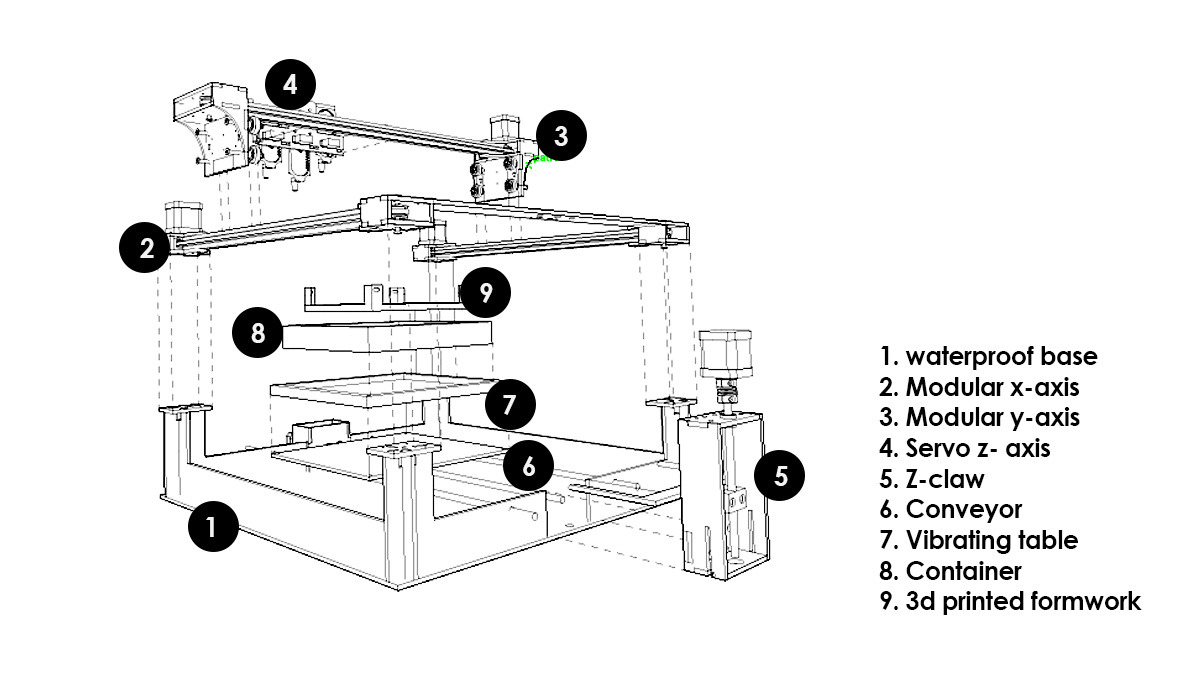
Parametric study to understand the mechanical system for a modular; extendable; eventual multi-axis machine.
Detailing was done in rhino3d using Openbuild blocks as blocks and reference.
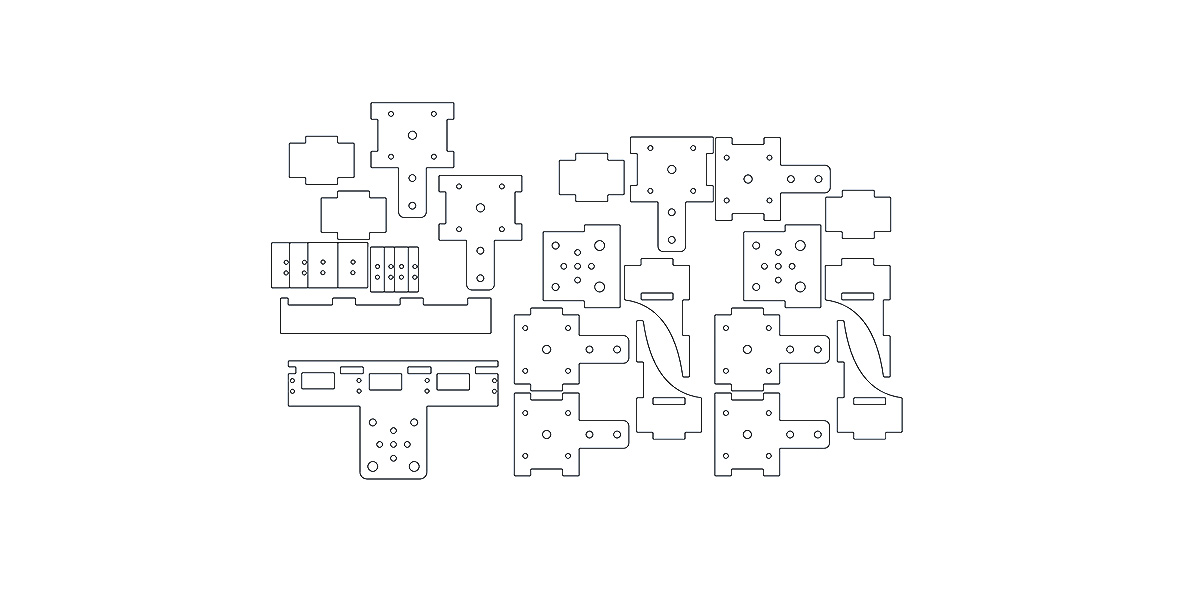
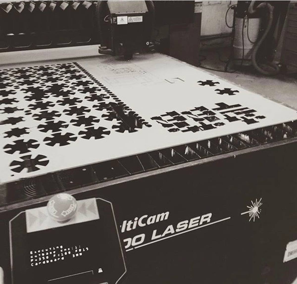
converting 3d to 2d laser cut files; as it tends to be to fastest way to fabricate in the lab; also very durable with acrylic or mdf (however mdf is only suggested for prototypes as will wear and tear quickly)
Make sure pressfit is tight and use some glue only where necessary; for additional strength.
Assembling everything together considering all screws; washers and bolts as well as electronics and motors. Base was used to hide all electronics.
Bill of quantities:
Although everything adds up into such a pricel this machine was actually build from recycled parts taken from a reprap and items found in the lab. Therefore reducing the price and 'recycling'.
hydrobot by joegalea on Sketchfab
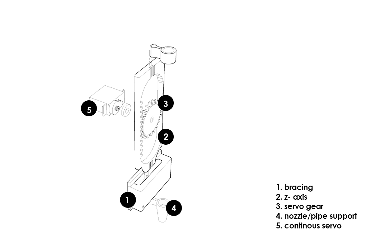
Servos are being used as a z axis to evetually acts as a possible valvue should the pump not be necessary for certain materials but also as a z movement for closer reach when filling the space.
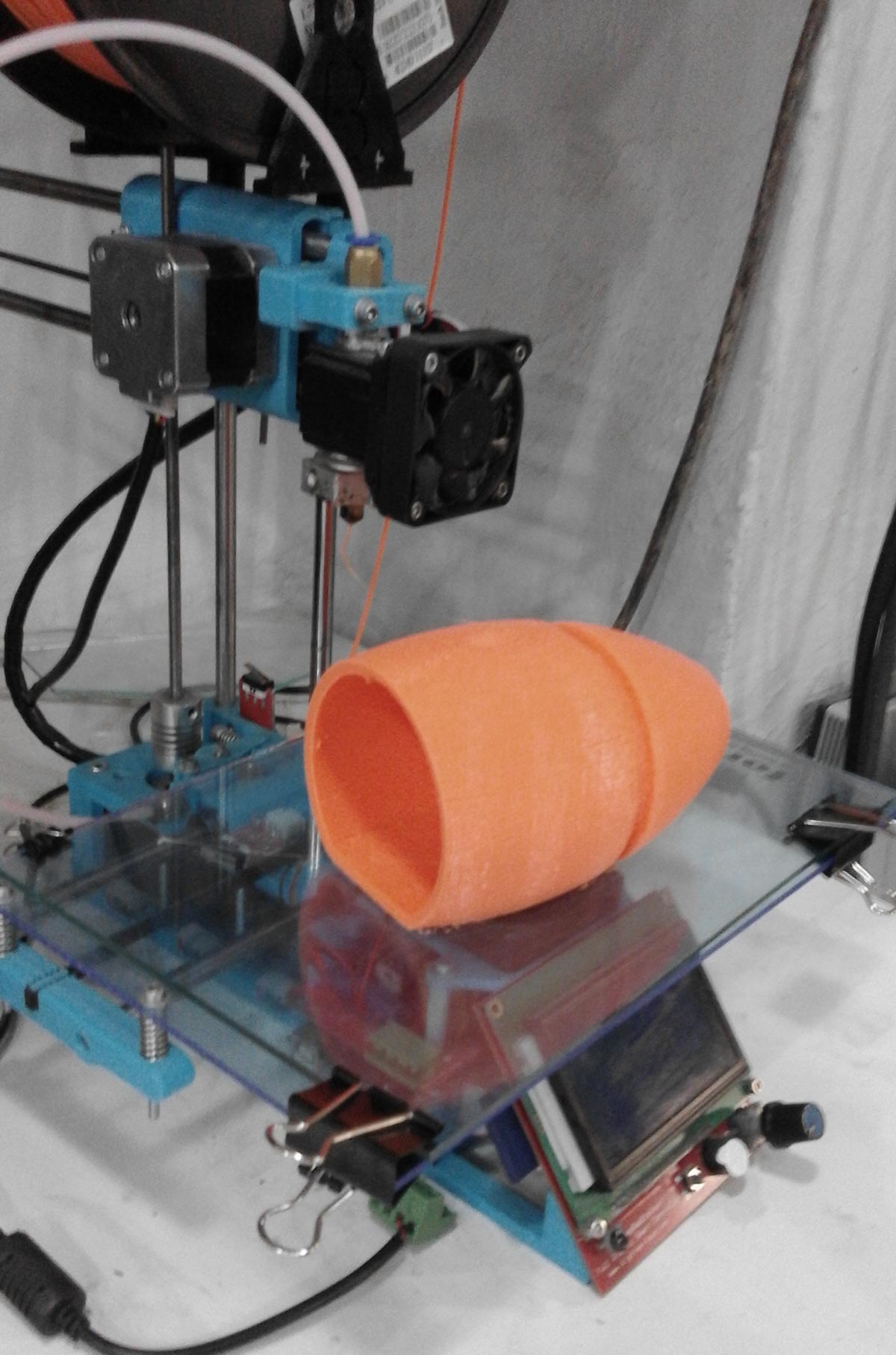
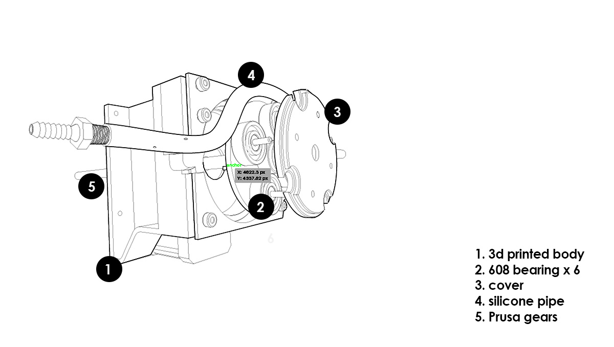
Below shows a grasshopper definition i wrote for a peristaltic pump. The pump squezes a silicone pipe and thus creates pressure which allows accurately controllable extrusion. A number of tests were made untill I had minimal friction and could get it to work properly. The process requires accurate fabrication, detailing and power.
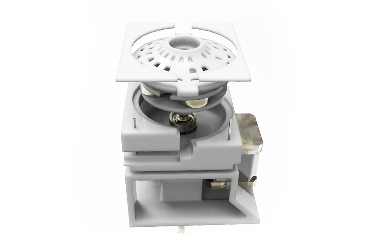
 This was the very first version; which still required a lot more details to work.
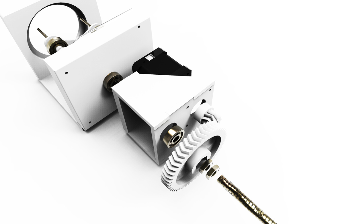
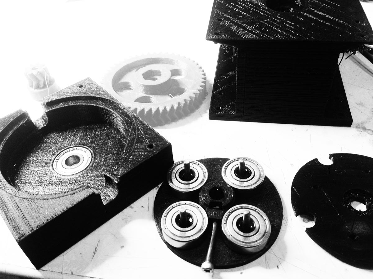
In this next version i decided to place prusa gears; to allow more power to the stepper motor by making it approximately 5 times slower in this case (47/9 ratio).
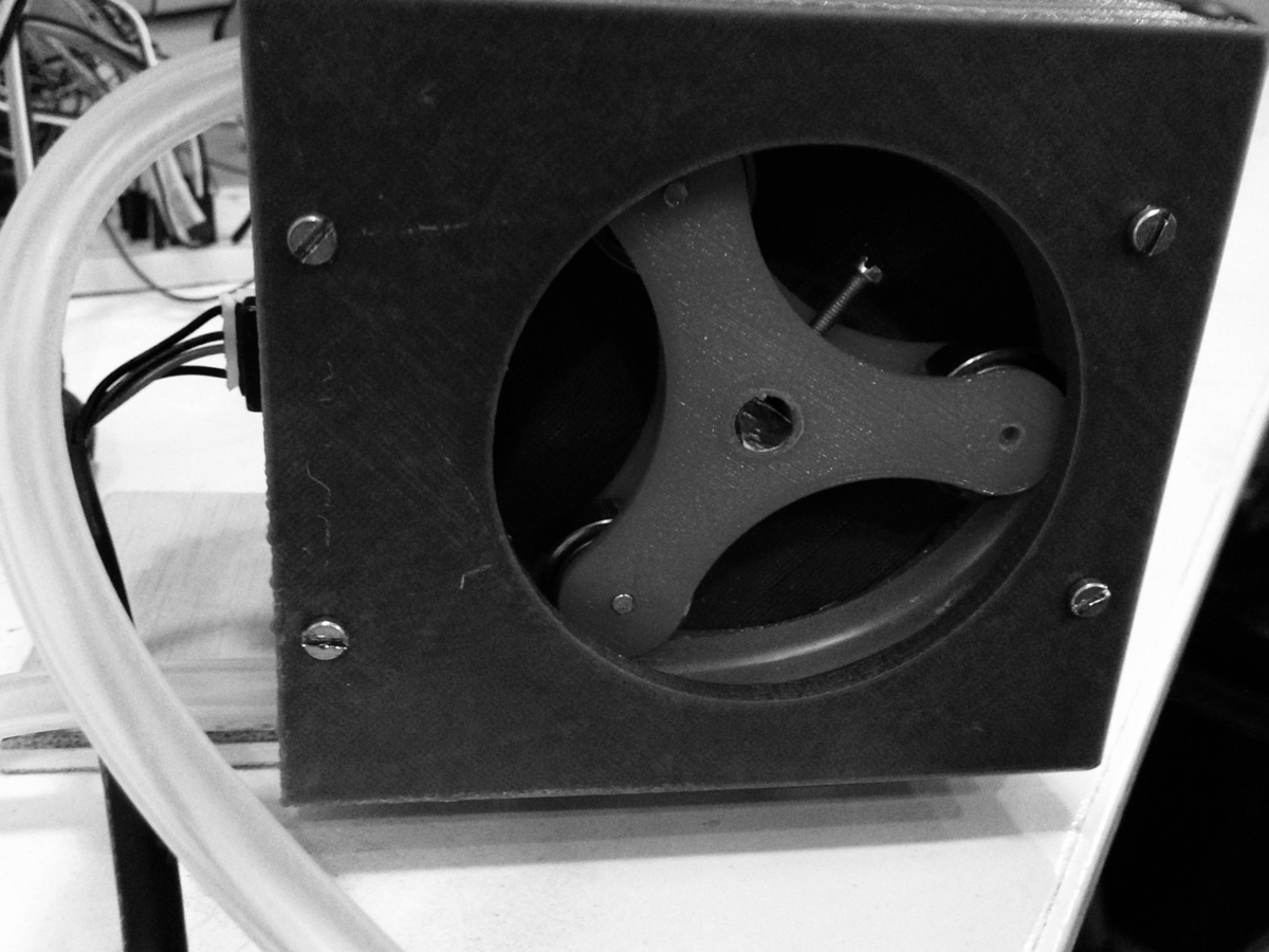
However because of the casing there was still a lot of friction and it was difficult to change things if i needed to. So I designed a next version..
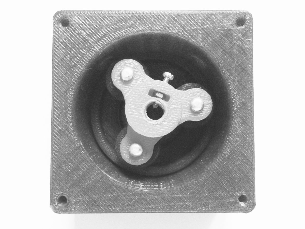
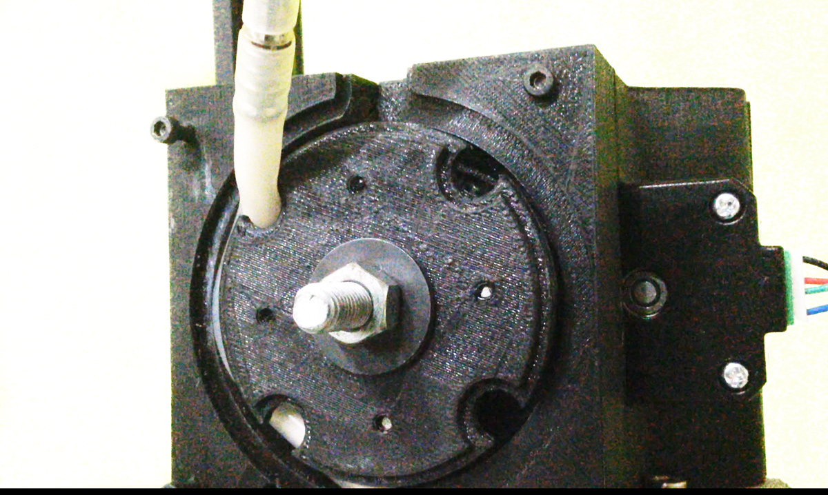
Version three was designed in a way to allow a lot of interchangeablity should something need arranging. I increased the number of ball bearings to squash the pipe but created less pipe squashing length. Occlusion (which refers to how much squeezing is happening to the tubes) could be adjusted by 3d printing one part and in fact this worked on the second try of approc .25 mm.
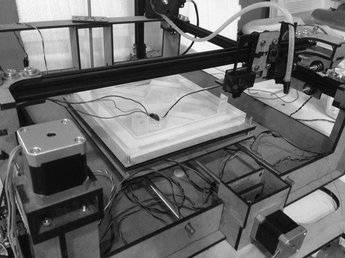
The video above shows one of the first tests showing extrusion; servo movement; and xy movement

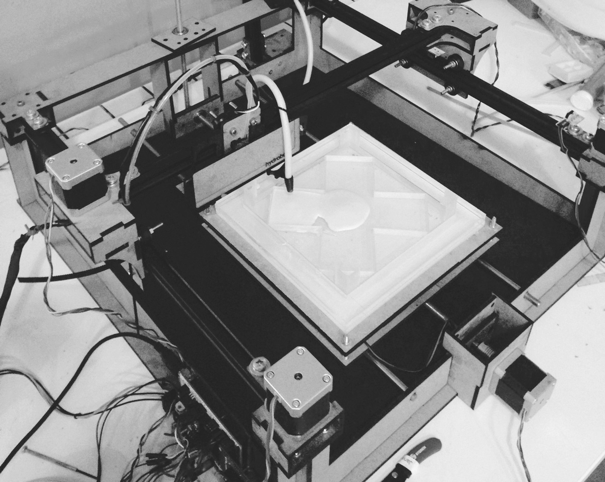
In the final weeks i added a second extruder as shown above by slightly modifying the marlin code. Here is a video showing it being tested.

This work is licensed under a Creative Commons Attribution-NonCommercial-ShareAlike 4.0 International License.
|Download all files
|Brief MIT
|Lecture Neil Gershelfeld