hola soy un mensaje secreto wiwiwi wawawa
WEEK 9&10: MECHANICAL DESIGN + MACHINE DESIGN
Assignment:
| | | | | | | | | | | | | | | | | | | | | | | | | | | | | | | | | | | | | | | | | | | | | | | | | | | | | | | | | | | | | | | | | | | | | | | | | | | | | | | | | | | | | | | | | | | | | | | | | | | | | | | | | | | | | | | | | | | | | | | | | | | | | | | | |
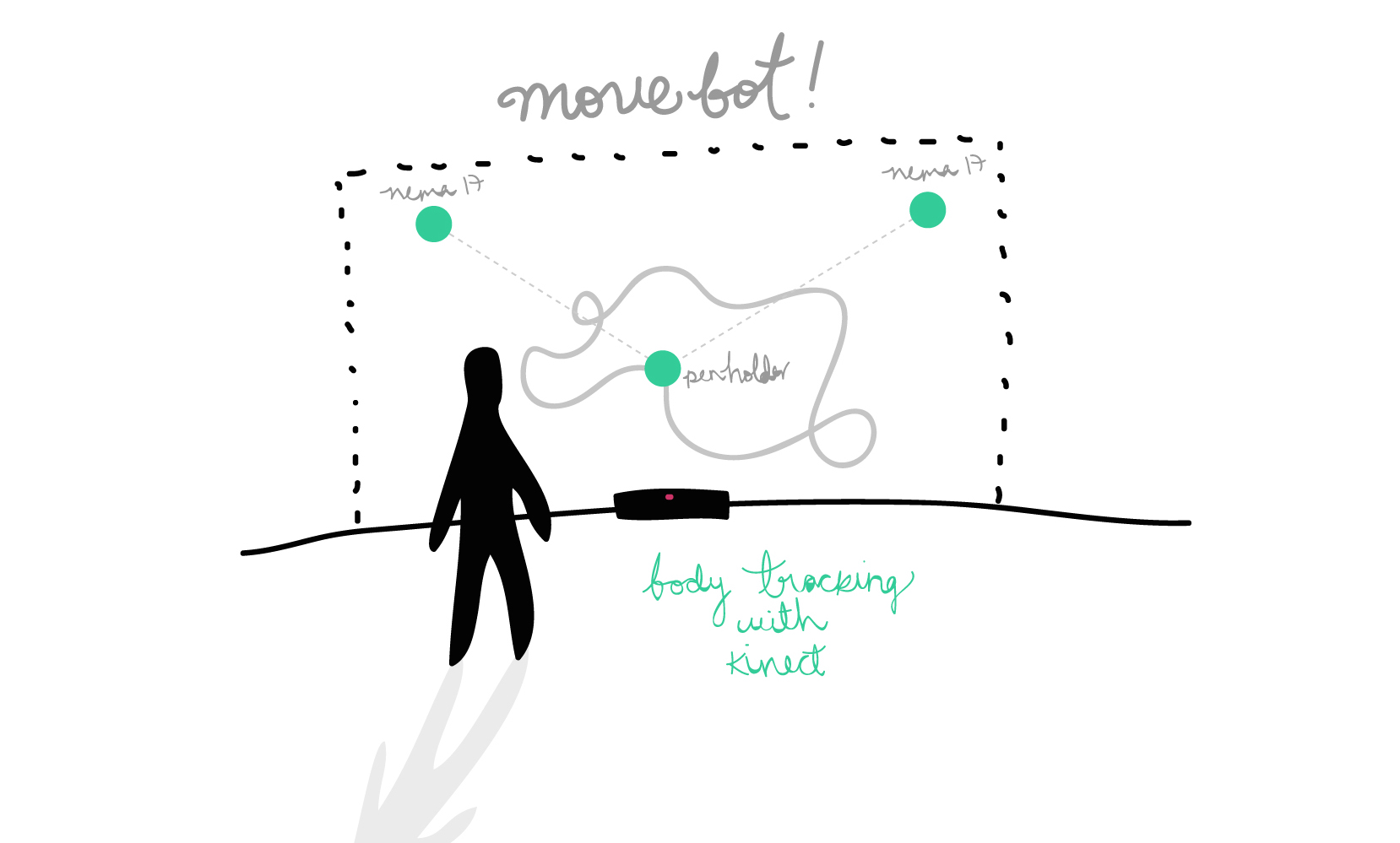
// Initial idea: Move-bot!
Real time / motion reactive / vertical drawing bot.
// Goals:
// Software:
// Hardware:
// Team:
| | | | | | | | | | | | | | | | | | | | | | | | | | | | | | | | | | | | | | | | | | | | | | | | | | | | | | | | | | | | | | | | | | | | | | | | | | | | | | | | | | | | | | | | | | | | | | | | | | | | | | | | | | | | | | | | | | | | | | | | | | | | | | | | |
//INFORMATION & RECOMMENDATIONS:
-You can read the shared documentation created by the team while researching for examples, techincal data, ideas, similar projects, etc. ----> here.
-We kept continously looking at Makelangelo an open source robot that draws posters and murals on paper, wood, glass, whiteboards, etc. Yeah yeah, basically a vertical drawing bot.
-We also learned from last year's Draw Bot by Gabriel Tanner and Alexander Walzer.
- "Death to Sharpie" project and processing code was helpful to understand some math/calculations.
-Read the datasheet of your motors. Understand the wiring and the current (V) needed for them to work fine.
| | | | | | | | | | | | | | | | | | | | | | | | | | | | | | | | | | | | | | | | | | | | | | | | | | | | | | | | | | | | | | | | | | | | | | | | | | | | | | | | | | | | | | | | | | | | | | | | | | | | | | | | | | | | | | | | | | | | | | | | | | | | | | | | |
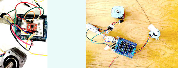
// 1ST STEPS: MAKE THOSE MOTORS MOVE!
We first decided to use Arduino so we could understand easily the anatomy of stepper motors, how to wire them, what drivers to use, steps/microsteps, etc.
About stepper motors: According to Wikipedia, they are "brushless DC motors" divided it's full rotation into a number of equal steps. Their main property is to convert a train of input pulses (mostly square wave pulses) into defined increment in the shaft position.
Stepper motors have toothed electromagnets inside a central gear made of iron, energized by an external driver or microcontroller. There are different types, and in the lab you'll find unipolar and bipolar ( a little bit more complex ).
About the wiring: Read your motor datasheet and understand which cables belong to which coils.
We found this useful colour code::

If you don't know what motor model you have, measure it with a calipper and google the dimensions + stepper motor. This method was tought to me by Martin Seymour.
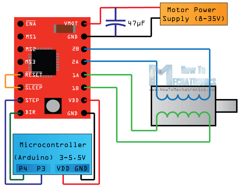
- We started using the Pololu Driver for a single motor and then tried DK Elektronics Motor shield.
If you are using one, you might take a look to this diagram (from howtomechatronics.com):
We used and modified Dejan Nedelkovski's Simple Stepper Motor Control Arduino code, to understand how steps work: Download me.
When using DK Elektronics Motor Shield, we experimented with AFmotor library examples, and tried to undesrtood the difference between single steps, double steps, interleave steps and microsteps. You can follow AFMotor from Adafruit's documentation here.


| | | | | | | | | | | | | | | | | | | | | | | | | | | | | | | | | | | | | | | | | | | | | | | | | | | | | | | | | | | | | | | | | | | | | | | | | | | | | | | | | | | | | | | | | | | | | | | | | | | | | | | | | | | | | | | | | | | | | | | | | | | | | | | | |
// DESIGN PROCESS
-After making a lot of tests with the steppers, we decided to split tasks so that everyone of us could solve specific necessities for our project.
For sure we knew that we wanted our window draw bot reactive to one person's movement.
We decided to solve techincal problems first and then continue creating our "concept" for generating a nice installation. Although we didn't achieve this part by far, we want to continue working on the project.
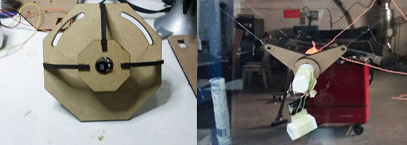
-MOTORS' SUPPORT by CARO: Designed in Solidworks and MDF. This laser cutted pieces would work as the support for the motors and also integrate space for special suction cups (wih a lock system) that Caro bought in Servei Estació.

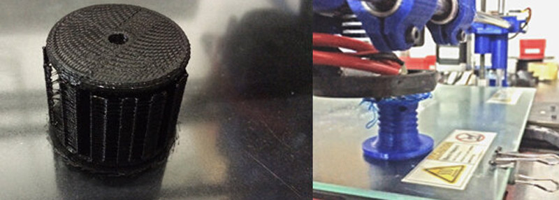
- HOOKS' REDESIGN by GORI: Based on the ones that were integrated on the suction cups, but for 3d printing allowing better for our drawbot purposes.
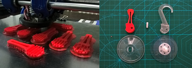
SPOOLS by JANAKI: These piece would roll or unroll our nylon thread used to carry the markerholder. She based her design on last year's drawbot Barcelona project. You can read her complete documentation about the spools ---> here.
CANSU worked on the design for the marker holder. She did two versions: one with the laser cutting techique and other 3d printed.
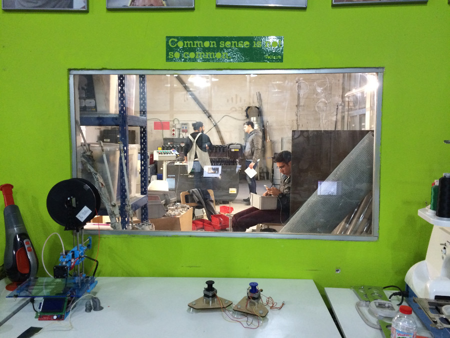
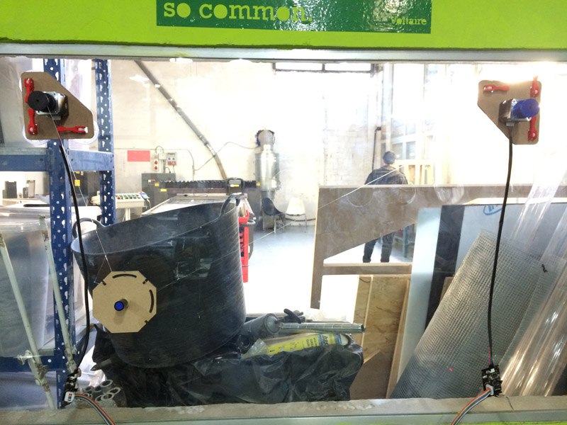
THE ALMOST COMPLETE DRAWBOT MACHINE!

It tooked us a while but we decided to use this window as our drawing canvas.
----------------------------------------------
---------- Kinect Data : My part! ------------
----------------------------------------------
As our inital idea was to make a real time drawing bot that follows gestures or body movements I decided to work with Micrsoft's Kinect Sensor ( First version ).
There are different methods to get the skeleton positions from this sensor: there's OpenKinect with Processing, documented by Daniel Shiffman and who by the way refers to a friend of mine (Tomás Lengeling) who worked on the development for Kinect V2 processing library for skeleton tracking. Yey Tom!
In this case I worked with Synapse, an application written and distributed by Ryan Challinor that gets the input data from Kinect and sends it out as OSC messages.
I used "Kinect-Via-Synapse" an open-source interface for use with the Kinect camera, Max/MSP, and Synapse. What the developer Kon Bellona writes in his description of the app makes me totally emphatize with him and in fact encourages me to develop my final project. He writes:
" My objective to this interface is to help streamline the creative process for musicians, composers, and digital artists wishing to get up and running with the Kinect. Ryan Challinor has done some great work compiling necessary OpenNI drivers for working with the Kinect straight out of the box. While there are inherent limitations, as with all programs, Kinect-Via-Synapse enables you to start programming creatively, without having to worry about establishing all the rough connections. The interface is meant to be performance ready."
This is how Synapse interface looks like:

Using udpsend object, I ask for specific data from Synapse every "n" miliseconds: /righthand_trackjoinpos
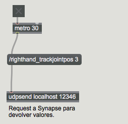
You can track: righthand, lefthand,rightelbow,leftelbow,rightfoot,leftfoot,rightknee, leftknee, head, torso, leftshoulder, rightshoulder, lefthip, righthio, closesthand.
This is the keepalive to cause joint positions to continue being spit out. Valid values to pass are: 1, to get _pos_body positions; 2, to get _pos_world positions; and 3, to get _pos_screen positions. In this case I used screen positions.
Then it's necessary to create an udpreceuve object specyfing which joints you want to track. For our experimentation I decided to work with the right hand data
OSC-route /righthand_pos_screen
Every joint contains 3 values: X,Y and Z. This is why I placed an unpack object.
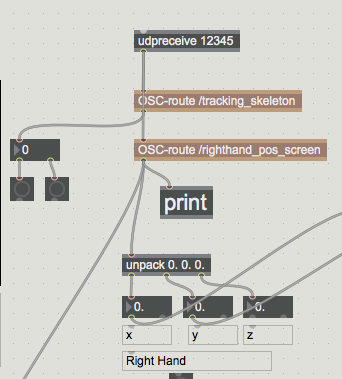
Kinect 1 sensor works with a resolution of 640x480 Px. so I created a maping (or scaling) system that could allow us translate 640x480 pixels canvas, to our real drawing bot canvas.
Unpacking x,y,z --> then round float numbers to integers --> then scale to get values between 0-400, 0-600 (400x600px).

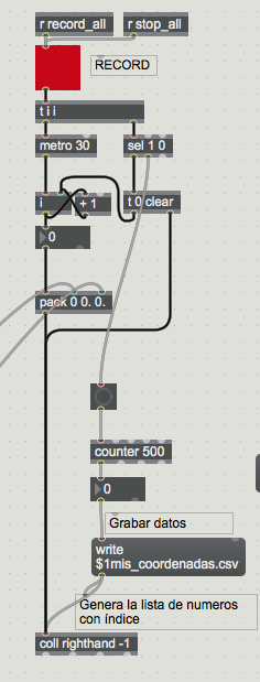
Based on a program designed by my good friend and great composer Nicolas Villa, I generated a recording system which will save in a .txt or .csv file a list of coordinates from the users's movement.
Recording data:
The idea was to write a little script in Python that could contonuosly read new .csv files and move the motors following user's movements.
But! We didn't had time to achieve this goal, so... if you want to take a look at the MAXMSP patch that I did so far, you can download it by clicking over the sparkling happy face:
Note: This is an improved version that formats the text.
EXPERIMENTATION:
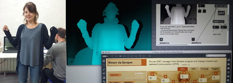
Some space understanding and movement tests using Synapse:
WP_20160411_21_00_19_Pro from Edgaar on Vimeo.
| | | | | | | | | | | | | | | | | | | | | | | | | | | | | | | | | | | | | | | | | | | | | | | | | | | | | | | | | | | | | | | | | | | | | | | | | | | | | | | | | | | | | | | | | | | | | | | | | | | | | | | | | | | | | | | | | | | | | | | | | | | | | | | | |
//GESTALT NODES SET UP
While each of us was designing and working on it's individual task, we decided to use Gestalt Nodes.
I personally wanted to keep on trying with Arduino, but Ferdi and Santi encouraged us to go for the Gestalt Nodes.
I have to say that I would have appreciated a lesson dedicated to Python, we had an incredible one for Arduino basics.
We mainly runned the python scripts into Caro's computer (Ubuntu) and Janaki's computer (Mac).
We followed this tutorial to make all the wiring and installations.
MATERIALS:
You'll need to follow the instructions from the tutorial depending on your operating system.
Our first square test using the xy_plotter.py from python looked like this:
drawbot from carovignoli@gmail.com on Vimeo.
//Processing
We also tried with last year's Processing sketch made by Francesca.


//GCode from Inkscape
And Gori understood how to generate GCode from inkcape. We first drew a star:
Drawbot + Inkscape.* from Citlali Limonada on Vimeo.

As you can see, all of our drawing tests resulted to bo distorted. This is because are drawing bot is in fact a POLAR BOT. This means that the machine uses strings to move the drawing point - marker, so tension and gravity interfere in the results.
There's good information about this ind of machines in a link found by Janaki here.
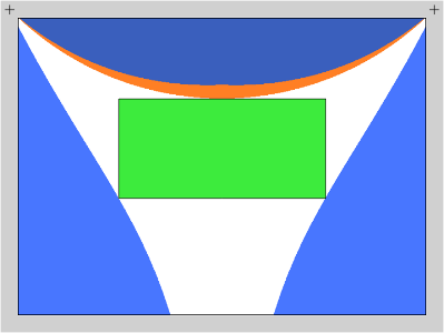
The plottinhg surface or - area that can be reached with the pen, contians a specific non-distorted drawing area. We made several tests to understand where in our window this area was located. It seemed that it was very very low and small.
So, looking at this diagram, we decided to draw a grid in different parts of the window trying to find where it appeared not to be distorted.
//KINECT + GESTALT NODES ( YEY! )
So I recorded myself moving my right hand, and saved a .txt and .crv file.
Then I MANUALLY edited the file erasing undesirable spaces, because at that moment I didn't have the MAXMSP patch with the text formatting solution.
You can tell that I wrongly made the mapping process. It resulted too small.
Drawbot reading data as gcode from right hand.
Drawbot + Kinect from Citlali Limonada on Vimeo.
| | | | | | | | | | | | | | | | | | | | | | | | | | | | | | | | | | | | | | | | | | | | | | | | | | | | | | | | | | | | | | | | | | | | | | | | | | | | | | | | | | | | | | | | | | | | | | | | | | | | | | | | | | | | | | | | | | | | | | | | | | | | | | | | |
//CONCLUSIONS & IDEAL INSTALLATION
Based on our experience, and the real possibilities to still achieve I made a diagram explaining the ideal installation that we could realize one of these days. If we manage to arrive to this point, you'll see pictures of it. Fingers Crossed!

To achieve this installation, there's a lot of in practice research to be done:
| | | | | | | | | | | | | | | | | | | | | | | | | | | | | | | | | | | | | | | | | | | | | | | | | | | | | | | | | | | | | | | | | | | | | | | | | | | | | | | | | | | | | | | | | | | | | | | | | | | | | | | | | | | | | | | | | | | | | | | | | | | | | | | | |
FILES:
Motor holders :D
MAX MSP: Go up in the page, and the link is a funny face.
INO's: :D
Spool: yey
Citlali Hernández - Fab Academy - 2016