Sander van Vliet
Fabacademy2016
@Fablab Amsterdam
Input Devices
Week 11 (13 april - 20 april)
Lecture
The lecture was about how you use a microcontroller for processing input and about various input sensors like switches, motion-, distance-, magnetic field-, temperature-, and light sensors, among others and the implications of using them. One that stood out from the rest was the step response sensor which can be utilized to measure an array of properties like resistance, capacitance, inductance, position, pressure, proximity, tilt, acceleration and humidity.
See this weeks' class lecture file to get an overview of the subjects of the lecture.
Assignment
- Add a sensor to a microcontroller board that you have designed and read it / measure something
A first test with a sensor I bought
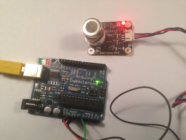
I started with a little test of the CO2 sensor I had ordered recently (MG811) which was delivered a few days ago. It is a sensor including the breakout board and I connected it to the analogue pin 0 of an Arduino Duemilanove (ATmega328p microcontroller).
 I used Arduino IDE to write a simple program to read the output of the sensor via the serial monitor.
 arduino sketch co2 analogue read serial source file - Arduino IDE
The sensor has not been calibrated so it is not clear what these values exactly mean, but it is nice to see the sensor is functioning. The first value was 674 and it gradually went up to 703 in the first 30 minutes. The reason probably is that the sensor is still heating up to its optimal operating temperature.
Make a CO2 breakout board myself
I want to make a breakout board for the CO2 sensor like this one myself, but did not have enough time to do it for this weeks assignment. I am working on it and would like to use that selfmade breakout board in my final project.
Designing and making a microcontroller board including a temperature sensor (thermistor)
I wanted to be able to measure temperature while I would use the CO2 sensor because the CO2 readings are influenced by temperature fluctuations. I will make a temperature sensor (thermistor) board based on the hello.temp.45 board on the class lecture page.
The parts list/bom consists of:
- 1x ATtiny45 microcontroller
- 1x 1UF capacitor
- 4x 10k Ω resistors
- 1x 10k Ω thermistor
- 1x 6 pin (2x3) ISP header
- 1x 6 pin FTDI header
I created a schematic in Eagle where I added the components and I connected them by adding the net names.
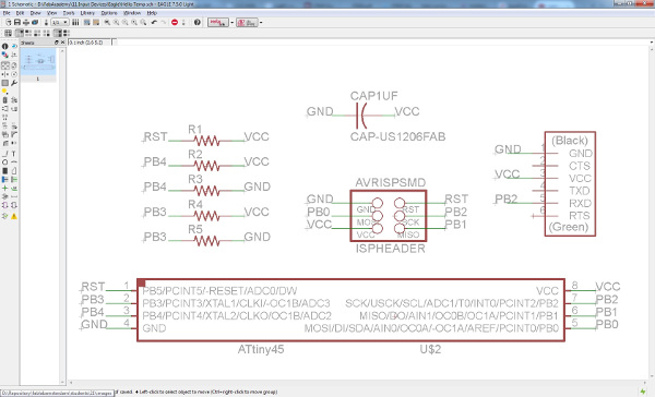 temperature sensor board schematic source file - Eagle
Then I opened the board view and placed the components where I wanted them and used autorouter to create the layout of the traces. Manually I created a cloud shaped outer dimension.
 temperature sensor board layout source file - Eagle
Then I exported the traces layer and the outer dimension layer to two separate .png files from Eagle, edited the dimension one using Gimp and used these two files below to mill the board using the Modela small milling machine.
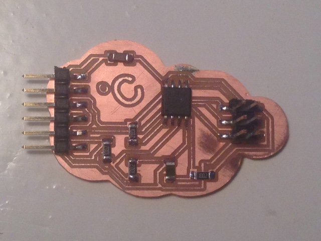
Then I stuffed the board aka soldered the components on the pcb and this was the result:
 Using my USBtinyISP and Arduino IDE I burned the bootloader on the temperature boards' ATtiny45 microcontroller and then I compiled the .hex file using this
C code and this makefile. The step where the microcontroller gets programmed has been included in the makefile. See the command line here.
Using my USBtinyISP and Arduino IDE I burned the bootloader on the temperature boards' ATtiny45 microcontroller and then I compiled the .hex file using this
C code and this makefile. The step where the microcontroller gets programmed has been included in the makefile. See the command line here.
Reading values from the temperature sensor board using the Arduino IDE serial monitor
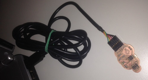
I connected the board to my laptop with an FTDI cable
 I opened Arduino IDE, set the serial port to com6 and opened the serial monitor. I set the baudrate to 9600 as defined in the C code. I expected to see temperature readings, but instead I saw the following infinite line of characters:
This must have something to do with the void put_char function and the sending of the framing, but although Neil explained this during the lecture, I still do not understand what is happening there. At this point all of a sudden I remembered that he used Python to display the temperature readings so it probably will not even work at all with the Arduino IDE serial monitor. I just assumed it would.
Reading values from the temperature sensor board using Python and the hello.temp.45.py script
So, now I went and tried to use Python and this script from Neil to see if I could receive and display temperature readings from the temperature board that way.
I opened a command prompt window and used the command python hello.temp.45.py com6. I received this error:
Traceback (most recent call last):
File "hello.temp.45.py", line 16, in
from numpy import log
ImportError: No module named numpy
so apparently I needed a Python module called numpy.
Installing the numpy Python module
On this page I found that I could download the numpy installation files for windows7 64bit from this page. The one I needed was numpy-1.11.0+mkl-cp27-cp27m-win_amd64.whl (the cp-number in the filename refers to the Python version; cp27=Python 2.7).
I had to follow these steps to install the numpy module:
- download get-pip. In an elevated command prompt navigate to its directory and install get-pip.py with the command:
python get-pip.py
The installation of get-pip.py creates files in C:\Python27\Scripts. These files include pip2, pip2.7 and pip.
- Copy the downloaded numpy-1.11.0+mkl-cp27-cp27m-win_amd64.whl into the directory C:\Python27\Scripts
- In command prompt navigate to the above directory and run the command:
pip2.7.exe install numpy-1.11.0+mkl-cp27-cp27m-win_amd64.whl
This was the response:
Installing collected packages: numpy. Successfully installed numpy-1.11.0
Success!
Then in command prompt I executed the command:
python hello.temp.45.py com6
and this time it worked as you can see in the movie below.
Extra test: connecting MG811 CO2 sensor to a FabKit
As a last test I connected my MG811 CO2 sensor to analogue pin 0 of the FabKit (ATmega328p microcontroller) I could use from Shirley and I was able to read the output of the sensor using the serial monitor from the Arduino IDE. The same outcome as seen at the top of this page when I used the Arduino board.